The article below comprehensively discusses all the basic facts, theories and information regarding the working and use of common electronic components such as resistors, capacitors, transistors, MOSFETs, UJTs, triacs, SCRs.
The various small basic electronic circuits explained here can be effectively applied as building blocks or modules for creating multistage circuits, by integrating the designs with each other.
We will begin the tutorials with resistors, and try to understand regarding their working and applications.
But before we begin let's quickly summarize the various electronic symbols that will be used in this article schematics.
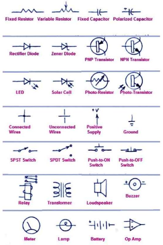
How Resistors Work
The function of resistors is to offer resistance to the flow of current. The unit of resistance is Ohm.
When a potential difference of 1 V is applied across a 1 Ohm resistor, a current of 1 Ampere will be forced through, as per the Ohm's law.
Voltage (V) acts like the potential difference across a resistor (R)
Current (I) constitutes the flow of electrons through the resistor (R).
If we know the values of any two these 3 elements V, I and R, the value of the 3rd unknown element could be easily calculated using the following Ohm's law:
V = I x R, or I = V/R, or R = V/I
When current flows through a resistor, it will dissipate power, which may be calculated using the following formulas:
P = V X I, or P = I2 x R
The result from the above formula will be in Watts, meaning the unit of power is watt.
It is always crucial to make sure that all the elements in the formula are expressed with standard units.
For example, if we millivolt is used, then it must be converted to volts, similarly miliamps should be converted to Ampere, and milliohm or kilo Ohm should be converted to Ohms while entering the values in the formula.
Fr most applications, the wattage of the resistor is in 1/4 watt 5% unless otherwise specified for special cases where the current is exceptionally high.
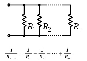
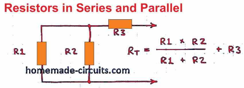
Resistors in Series and Parallel Connections
Resistor values can be adjusted to different customized values by adding assorted values in series or parallel networks. However, the resultant values of such networks has to be calculated precisely through formulas as given below:

How to Use Resistors
A resistor is normally used to limit current through a series load such as a lamp, an LED, an audio system, a transistor etc. in order to protect these vulnerable devices from over-current situations.
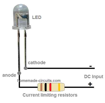
In the above example, the current though the LED could be calculated using Ohm's law.
However, the LED may not begin to illuminate properly until its minimum forward voltage level is applied, which may be anywhere between 2 V to 2.5 V (for RED LED), therefore the formula which can be applied for calculating the current through the LED will be
I = (Supply DC - 2) / R
Assuming the supply input DC is 6V, and the optimal LED current is 20 mA, then the value can be calculated as:
R = (Supply DC - 2) / I = 6 - 2 / 0.02 = 200 ohm
Potential Divider
Resistors can be used as potential dividers, for reducing the supply voltage to a desired lower level, as shown in the following diagram:
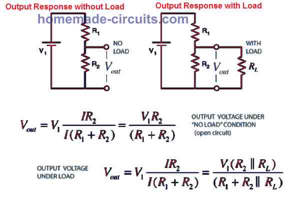
However, such resistive dividers can be used for generating reference voltages, only for high impedance sources. The output cannot be used for a operating a load directly, since the involved resistors would make the current significantly low.
Wheatstone Bridge Circuit
A wheatstone bridge network is a circuit which is used for measuring resistor values with great accuracy.
The fundamental circuit of a wheatsone bridge network is shown below:

The working details of the wheatstone bridge, and how to find precise results using this network is explained in the diagram above.
Precision Wheatstone Bridge Circuit
The wheatstone bridge circuit shown in the next figure enables the user to measure the value of an unknown resistor (RX) with very high precision.

For this, the rating of the known resistors R1 and R2 needs to be accurate too (1% type). R3 should be a potentiometer, which could be precisely calibrated for the intended readings. R5 can be a preset, positioned as a current stabilizer from the power source.
To initiate the testing procedure, the user must adjust R3 until a zero reading is obtained on the meter M1.
The condition is, R3 will be equal to the adjustment of R1. In case R1 is not identical to R2, then the following formula could be used to determine the value of RX. RX = (R1 x R3) / R2
Capacitors
Capacitors work by storing an electric charge within a couple of internal plates, which also form the terminal leads of the element. The unit of measurement for capacitors is Farad.
A capacitor rated at 1 Farad when connected across a supply of 1 volt will be able to store a charge of 6.28 x 10¹⁸ electrons.
However, in practical electronics, capacitors in Farads are considered too big and are never used. Instead much smaller capacitor units are used such as picofarad (pF), nanofarad (nF), and microfarad (uF).
The relationship between the above units can be understood from the following table, and this can be also used for converting one unit into another.
- 1 Farad = 1 F
- 1 microfarad = 1 uF = 10-6 F
- 1 nanofarad = 1 nF = 10-9 F
- 1 picofarad = 1 pF = 10-12 F
- 1 uF = 1000 nF = 1000000 pF
Capacitor Charging and Discharging
A capacitor will instantly charge when its leads are connected across an appropriate voltage supply.
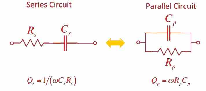
The charging process can be delayed or made slower by adding a resistor in series with the supply input, as depicted in the above diagrams.
The discharging process is also similar but in the opposite way. The capacitor will instantly discharge when its leads are shorted together. The discharge process could be proportionately slowed down by adding a resistor in series with the leads.
Capacitor in Series
Capacitors can be added in series by connecting their leads with each other as shown below. For polarized capacitors, the connection should be such that the anode of one capacitor connects with the cathode of the other capacitor, and so on. For non-polar capacitors the leads can be connected any way round.
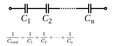
When connected in series the capacitance value decreases, for example when two 1 uF capacitors are connected in series, the resultant value becomes 0.5 uF. This seems to be just the opposite of resistors.
When connected in series connection, it adds up the voltage rating or the breakdown voltage values of the capacitors.
For example, when two 25 V rated capacitors are connected in series, their voltage tolerance range adds up and increases to 50 V
Capacitors in Parallel
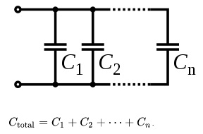
Capacitors can be also connected in parallel by joining their leads in common, as shown in the above diagram. For polarized capacitors, the terminals with like poles must be connected with each other, for non-polar caps this restriction can be ignored.
When connected in parallel, the resultant total value of capacitors increases, which is just the opposite in the case of resistors.
Important: A charged capacitor can hold the charge between its terminals for a significantly long time.
If the voltage is high enough in the range of 100 V and higher can inflict painful shock if the leads are touched.
Smaller levels of voltages can have enough power to even melt a small piece of metal when the metal is brought between the leads of the capacitor.
How to Use Capacitors
Signal Filtering: A capacitor can be used for filtering voltages in a few ways. When connected across an AC supply it can attenuate the signal by grounding some of its content, and allowing an average acceptable value at the output.

DC Blocking: A capacitor can be used in series connection to block a DC voltage and pass an AC or pulsating DC content through it.
This feature allows audio equipment to use capacitors at their input/output connections to enable the passage of the audio frequencies, and prevent the unwanted DC voltage from entering the amplification line.

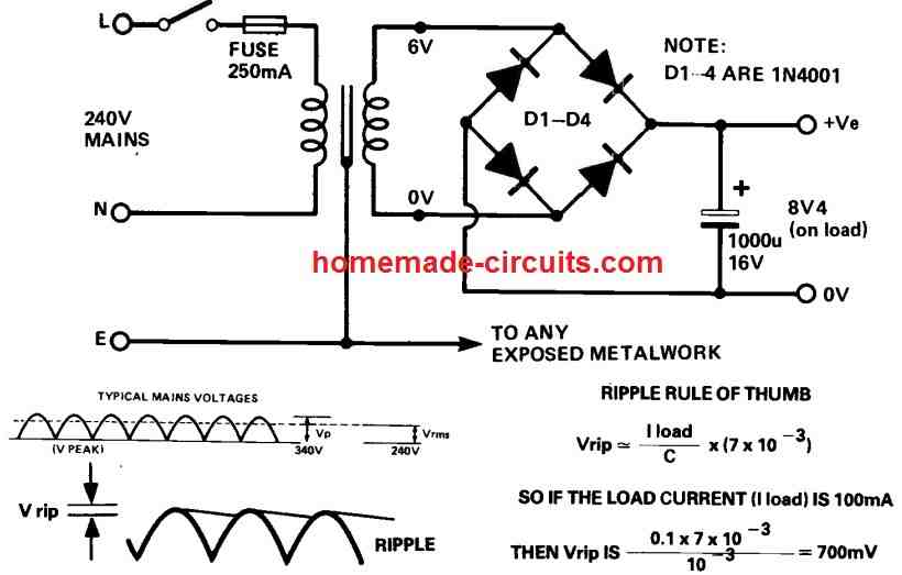
Power Supply Filter: Capacitors also work as DC supply filters in power supply circuits. In a power supply, after rectification of the AC signal the resultant DC may be full of ripple fluctuations.
A large value capacitor connected across this ripple voltage results in a significant amount filtration causing the fluctuating DC to become a constant DC with ripples reduced to an amount as determined by the value of the capacitor.
How to Make an Integrator
The function of an integator circuit is to shape a square wave signal into a triangle waveform, through a resistor, capacitor or RC network, as shown in the above figure.
Here we can see the resistor is at the input side, and is connected in series with the line, while the capacitor is connected on the output side, across the resistor output end and the ground line.
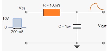
The RC components act like a time constant element in the circuit, whose product must be 10 times higher than the period of the input signal. Otherwise, it may cause the amplitude of the output triangle wave to be reduced.
In such conditions the circuit will function like a low pass filter blocking high frequency inputs.
How to Make a Differentiator
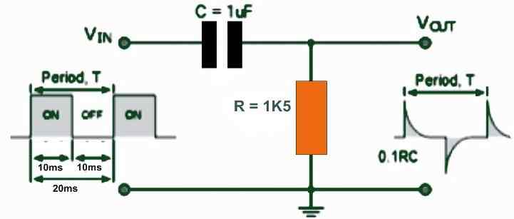
The function of a differentiator circuit is to convert a square wave input signal into a spiked waveform having a sharp rising and a slow falling waveform.
The value of the RC time constant in this case must be 1/10th of the input cycles. Differentiator circuits are normally used for generating short and sharp trigger pulses.
Understanding Diodes and Rectifiers
Diodes and rectifiers are categorized under semiconductor devices, which are designed to pass current only in one specified direction while block from the opposite direction.
However, a diode or diode based modules will not begin to pass current or conduct until the necessary minimum forward voltage level is acquired.
For example a silicon diode will conduct only when the applied voltage is above 0.6 V, while a germanium diode will conduct at a minimum of 0.3 V.
If two two diodes are connected in series then this forward voltage requirement will also double to 1.2 V, and so on.
Using Diodes as Voltage Dropper
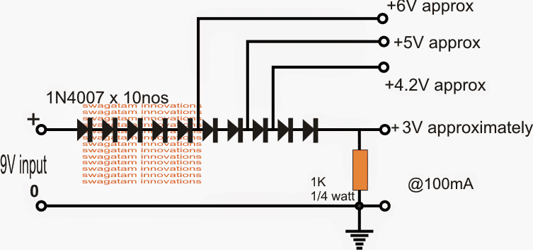
As I will explained in the previous paragraph, diodes require around 0.6 V to begin conducting, this also means that the diode would drop this level of voltage across its output and ground. For example, if 1 V is applied, the diode will produce 1 - 0.6 = 0.4 V at its cathode.
This feature allows diodes to be used as voltage dropper. Any desired voltage drop can be achieved by connecting the corresponding number of diodes in series. Therefore if 4 diodes are connected in series, it will create a total deduction of 0.6 x 4 = 2.4 V at the output and so on.
The formula for calculating this given below:
Output Voltage = Input Voltage - (no of diodes x 0.6)
Using Diode as Voltage Regulator
Diodes due to their forward voltage dropping feature can be also used for generating stable reference voltages, as shown in the folowing diagram. The output voltage can be calculated through the following formula:
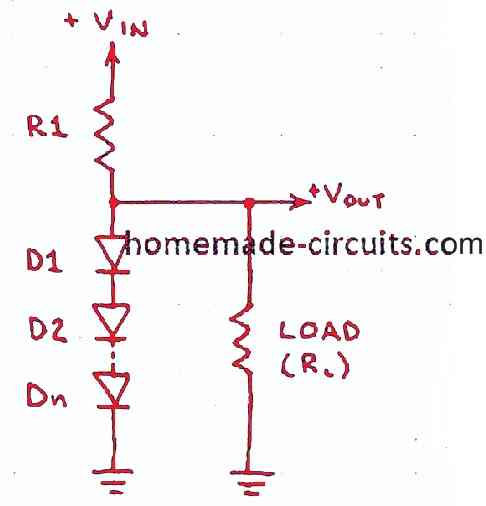
R1 = (Vin - Vout) / I
Make sure to use proper wattage rating for the D1 and R1 components as per the wattage of the load. They must be rated at least two times more than the load.
Triangle to Sine Wave Converter
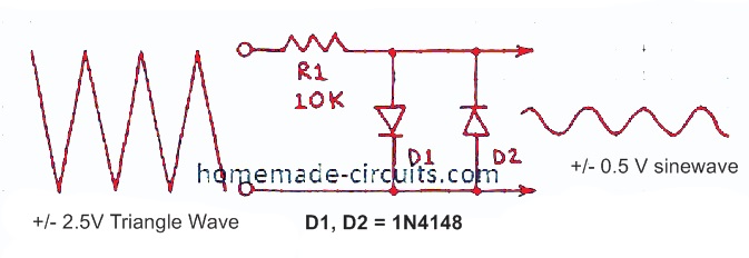
Diodes can also work as triangle wave to sine wave converter, as indicated in the above diagram. The amplitude of the output sine wave will depend on the number of diodes in series with D1, and D2.
Peak Reading Voltmeter
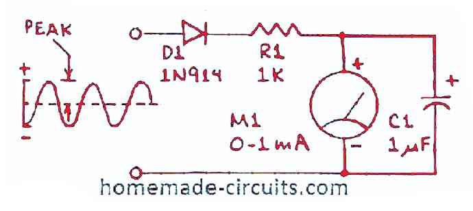
Diodes may be also configured for getting peak voltage reading on a voltmeter. Here, the diode works like a half wave rectifier, allowing half cycles of the frequency to charge the capacitor C1 to the peak value of the input voltage. The meter then shows this peak value through its deflection.
Reverse Polarity Protector
This is one of the very common applications of diode, which uses a diode to protect a circuit against accidental reverse supply connection.
Back EMF and Transient Protector
When an inductive load is switched through a transistor driver or an IC, depending on its inductance value, this inductive load could generate high voltage back EMF, also called reverse transients, which may have the potentials of causing an instant destruction of the driver transistor or the IC.
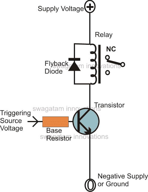
A FLYBACK DIODE placed in parallel to the load can easily circumvent this situation. Diodes in this type of configuration is also known as freewheeling diode.
In a transient protector application, a diode is normally connected across an inductive load to enable the bypassing of a reverse transient from the inductive switching through the diode.
This neutralizes the spike, or the transient by short circuiting it through the diode. If the diode is not used, the back EMF transient would pass through the driver transistor or the circuit in the reverse direction, causing an instant damage to the device.
Meter Protector
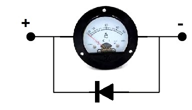
A moving coil meter can be a very sensitive piece of instrument, which can get severely damaged if the supply input is reversed. A diode connected in parallel can protect the meter from this situation.
Waveform Clipper
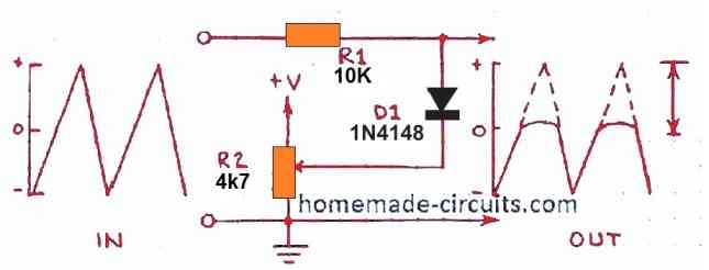
A diode can be used to chop and clip off the peaks of a waveform, as shown in the above diagram, and create an output with reduced average value waveform. The resistor R2 can be a pot for adjusting the clipping level.
Full wave Clipper
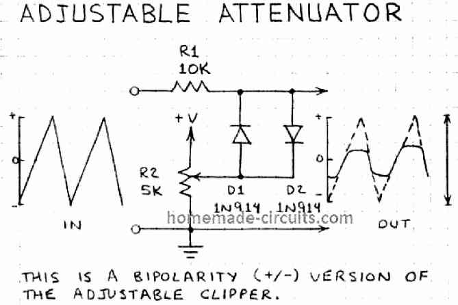
The first clipper circuit has the capability of clipping the positive section of the waveform. For enabling clipping of both the ends of an input waveform, two diodes could be used in parallel with opposite polarity, as shown above.
Half wave Rectifier
When a diode is used as a half wave rectifier with an AC input, it blocks the half reverse input AC cycles, and allows only the other half to pass through it, creating half wave cycle outputs, hence the name half wave rectifier.
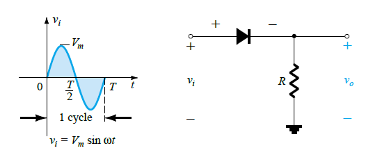
Since the AC half cycle are removed by the diode, the output becomes DC and the circuit is also called half wave DC converter circuit. Without a filter capacitor, the output will be a pulsating half wave DC.

The previous diagram can be modified using two diodes, for getting two separate outputs with opposite halves of the AC rectified into corresponding DC polarities.
Full Wave Rectifier
A full wave rectifier, or a bridge rectifier is a circuit built using 4 rectifier diodes in a bridged configuration, as depicted in the above figure. The specialty of this bridge rectifier circuit is that it is able to convert both the positive and the negative half cycles of the input into a full wave DC output.
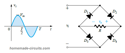
The pulsating DC at the output of the bridge will have a frequency twice of the input AC due to the inclusion of the negative and the positive half cycle pulses into a single positive pulse chain.
Voltage Doubler Module
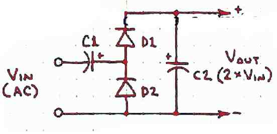
Diodes can be also implemented as voltage doubler by cascading a couple diodes with a couple of electrolytic capacitors.
The input should be in the form of pulsating DC or an AC, which causes the output to generate approximately two time more voltage than the input. The input pulsating frequency can be from a IC 555 oscillator.
Voltage Doubler using Bridge Rectifier
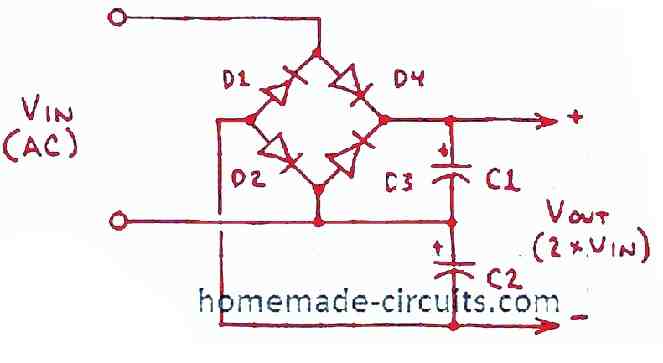
A DC to DC voltage doubler could be also implemented using a bridge rectifier and a couple of electrolytic filter capacitors, as shown in the above diagram. Using a bridge rectifier will result in higher efficiency of the doubling effect in terms of current compared to the previous cascaded doubler.
Voltage Quadrupler
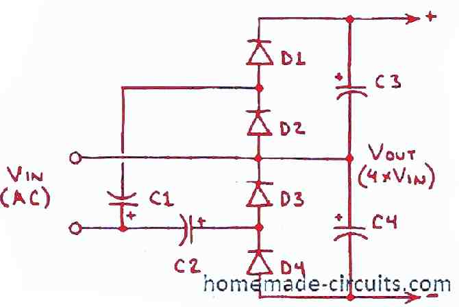
The above explained voltage multiplier circuits are designed to generate 2 times more output than the input peak levels, however, if an application needs even higher levels of multiplication in the order of 4 times more voltage then the this voltage quadrupler circuit could be applied.
Here, the circuit is made using 4 numbers of cascaded diodes and capacitors for getting 4 times more voltage at the output then the input frequency peak.
Diode OR Gate
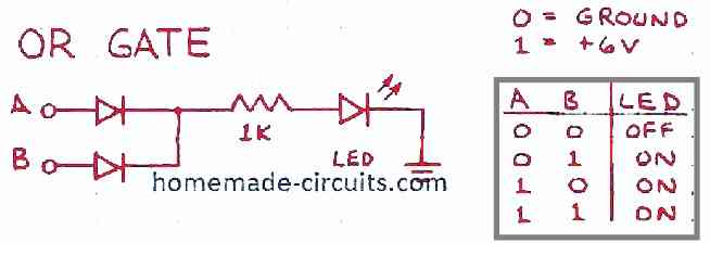
Diodes can be wired to imitate an OR logic gate using the circuit as shown above. The adjoining truth table shows the output logic in response to a combination of two logic inputs.
NOR Gate using Diodes
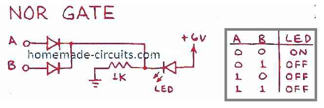
Just like an OR gate, a NOR gate can be also replicated using a couple of diodes as shown above.
AND Gate NAND Gate using Diodes
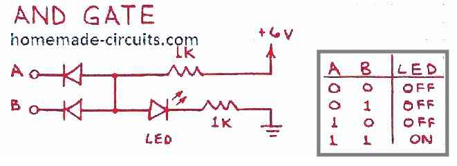
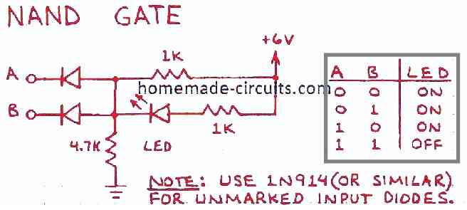
It may be also possible to implement other logic gates such as AND gate and NAND gate using diodes as exhibited in the above diagrams. The truth tables shown beside the diagrams provide the exact required logic response from the set ups.
Zener Diode Circuit Modules
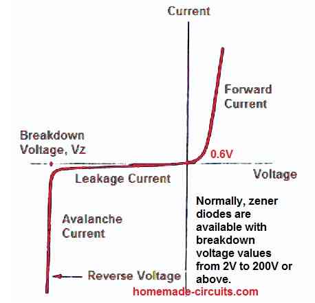
The difference between a rectifier and zener diode is that, a rectifier diode will always block reverse DC potential, while the a zener diode will block the reverse DC potential only until its breakdown threshold (zener voltage value) is reached, and then it will switch ON fully and allow the DC to pass through it completely.
In the forward direction, a zener will act similar to a rectifier diode and will allow the voltage to conduct once the minimum forward voltage of 0.6 V is reached.
Thus, a zener diode can be defined as a voltage sensitive switch, which conducts and switches ON when a specific voltage threshold is reached as determined by the breakdown value of the zener.
For example a 4.7 V zener will begin conducting in the reverse order a soon as the 4.7 V is reached, while in the forward direction it will need just a potential; of 0.6 V. The graph below sums up the explanation quickly for you.
Zener Voltage Regulator
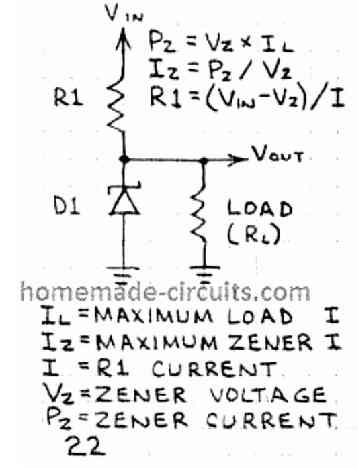
A zener diode can be used to create stabilized voltage outputs as shown in the adjoining diagram, by using a limiting resistor. The limiting resistor R1 limit the maximum tolerable current for the zener and protects it from burning due to over current.
Voltage Indicator Module
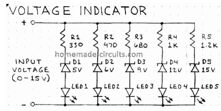
Since zener diodes are available with a variety of breakdown voltage levels, the facility could be applied for making an effective yet simple voltage indicator using appropriate zener rating as shown in the above diagram.
Voltage Shifter
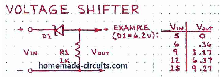
Zener diodes can be also used for shifting a voltage level to some other level, by using suitable zener diode values, as per the needs of the application.
Voltage Clipper

Zener diodes being a voltage controlled switch can be applied to clip the amplitude of an AC waveform to a lower desired level depending on its breakdown rating, as shown in the diagram above.
Bipolar Junction Transistor (BJTs) Circuit Modules
Bipolar junction transistors or BJTs are one of the most important semiconductor devices in the electronic component family, and it forms the building blocks for almost all electronic based circuits.
BJTs are versatile semiconductor devices which can be configured and adapted for implementing any desired electronic application.
In the following paragraphs a compilation of BJT application circuits which could be employed as circuit modules for constructing countless different customized circuit applications, as per the requirement of the user.
Let's discuss them in details through the following designs.
OR Gate Module
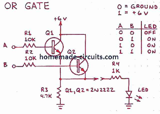
Using a couple of BJTs and some resistors, a quick OR gate design could be made for implementing the OR logic outputs in response to different input logic combinations as per the truth table shown in the diagram above.
NOR Gate Module
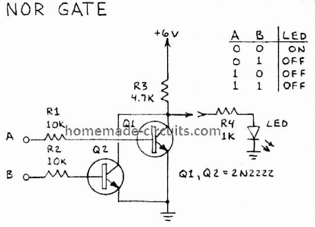
With some suitable modifications the above explained OR gate configuration could be transformed into a NOR gate circuit for implementing the specified NOR logic functions.
AND Gate Module
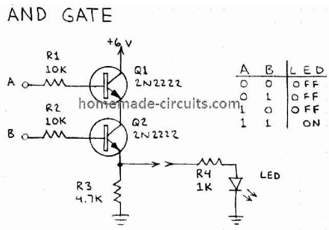
If you do not have a quick access to a AND gate logic IC, then probably you can configure a couple of BJTs for making an AND logic gate circuit and for executing the above indicated AND logic functions.
NAND Gate Module
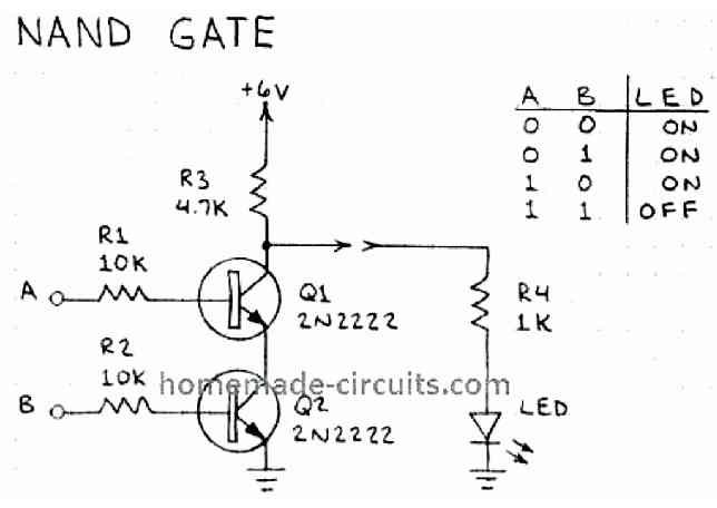
The versatility of BJTs allows BJTs to make any desired logic function circuit, and a NAND gate application is no exception.
Again, using a couple of BJTs you can quickly build and enforce a NAND logic gate circuit as depicted in the figure above.
Transistor as Switches
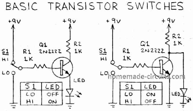
As indicated in the diagram above a BJT can be simply used as a DC switch for switching a suitably rated load ON/OF. In the shown example, the mechanical switch S1 imitates a logic high or low input, which causes the BJT to switch ON/OFF the connected LED.
Since an NPN transistor is shown, the positive connection of S1, cause the BJT switch ON the LED in the left circuit, while in the right side circuit LED is switched OFF when the S1 is positioned at the positive end of the switch.
Voltage Inverter
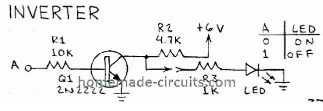
A BJT switch as explained in the previous paragraph can be also wired as voltage inverter, meaning for creating output response opposite to the input response.
In the example above, the output LED will switch ON in the absence of a voltage at point A, and will switch OFF in the presence of a voltage at point A.
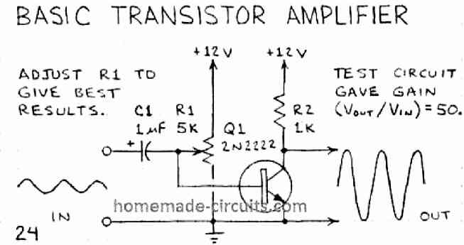
BJT Amplifier Module
A BJT can be configured as a simple voltage/current amplifier for amplifying a small input signal into much higher level, equivalent to the supply voltage used. The diagram is shown in the following diagram
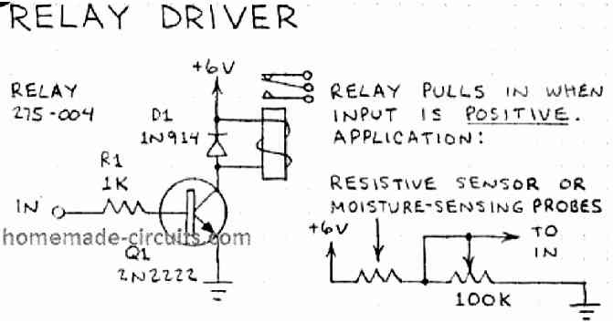
BJT Relay Driver Module
The transistor amplifier explained above can be used for applications like a relay driver, in which a higher voltage relay could be triggered through a tiny input signal voltage as shown in the below given image.
The relay could be triggered in response to an input signal received from a specific low signal sensor or detector device, like an LDR, Microphone, PIR, LM35, thermistor, ultrasonic etc.
Relay Controller Module
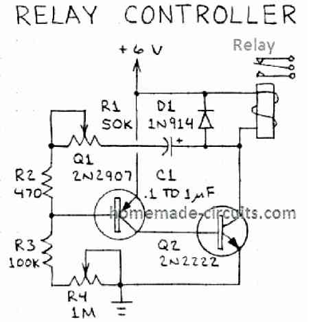
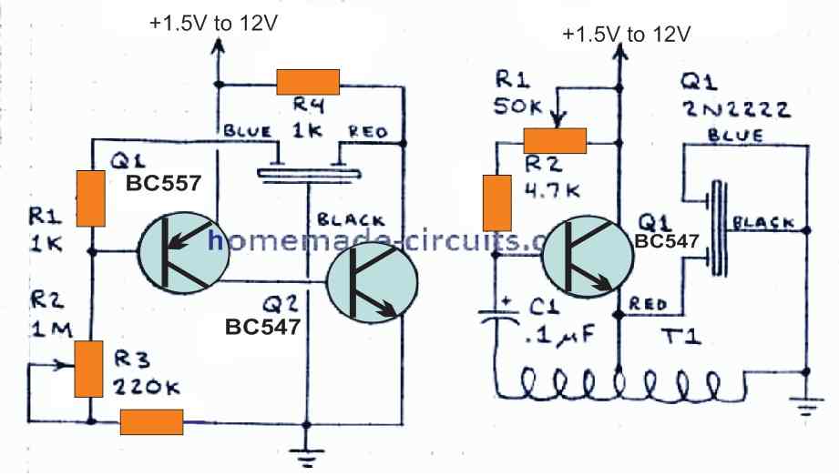
Just two BJTs can be wired like a relay flasher as shown in the image below. The circuit will pulse the relay ON/OFF at a particular rate which can be adjusted using the two variable resistor R1 and R4.
Constant Current LED Driver Module
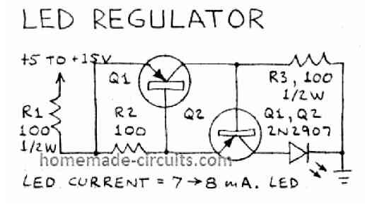
If you are looking for a cheap yet extremely reliable current controller circuit your LED, you can quickly build it using the two transistor configuration as show in the following image.
3V Audio Amplifier Module
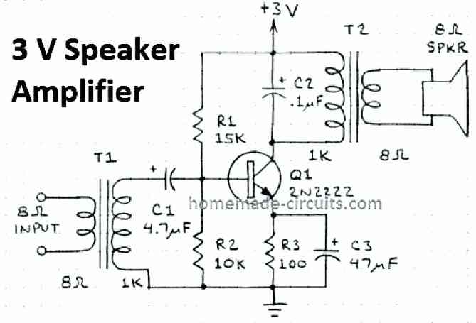
This 3 V audio amplifier can be applied as the output stage for any sound system such as radios, microphone, mixer, alarm etc.
The main active element is the transistor Q1, while the input output transformers act like complementary stages for generating a high gain audio amplifier.
Two Stage Audio Amplifier Module
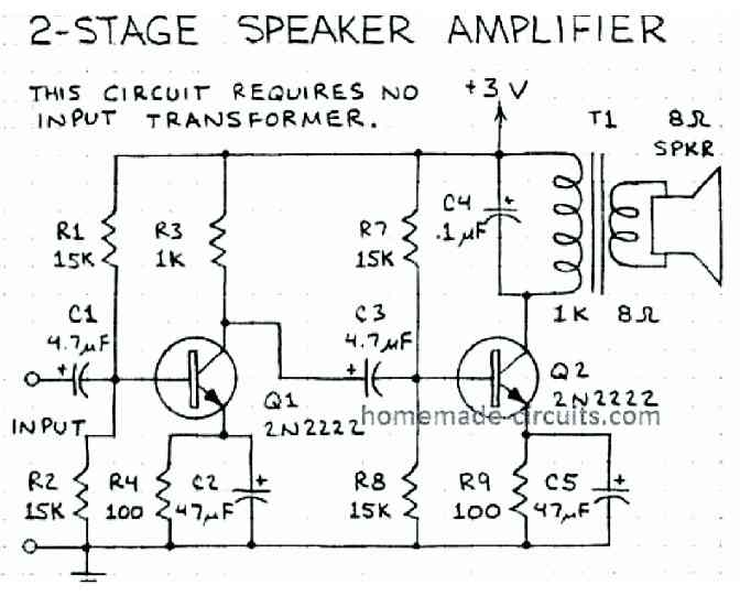
For higher amplification level, a two transistor amplifier can be employed as shown in this diagram. Here an extra transistor is included at the input side, although the input transformer has been eliminated, making the circuit more compact and efficient.
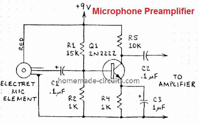
MIC Amplifier Module
The image below shows a basic preamplifier circuit module, which can used with any standard electret MIC for raising its small 2 mV signal into a reasonably higher 100 mV level, which may be just suitable for integrating to a power amplifier.
Audio Mixer Module
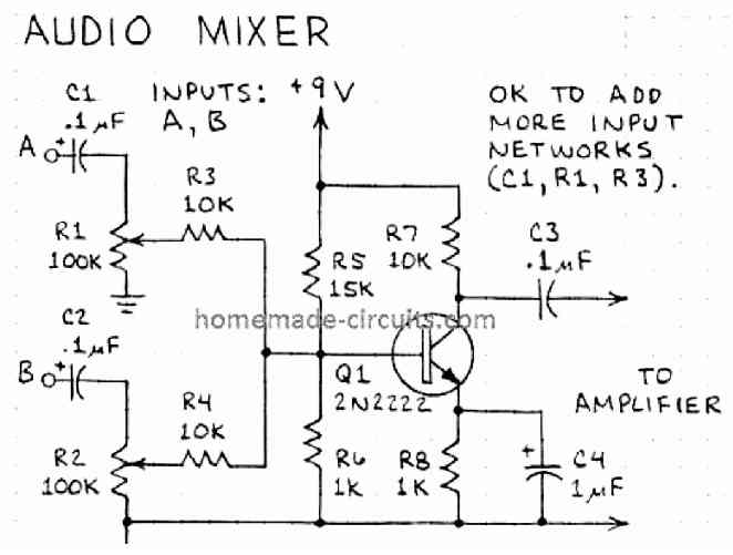
If you have an application in which two different audio signals needs to be mixed and blended together into a single output, then the following circuit will work nicely. It employs a single BJT and a few resistors for the implementation.
The two variable resistors at the input side determine the amount of signal that can be mixed across the two sources for amplification at the desired ratios.
Simple Oscillator Module
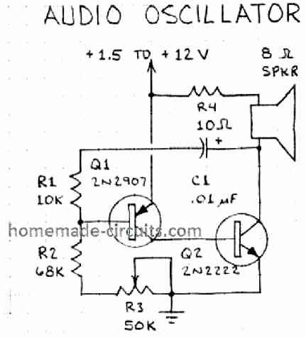
An oscillator is actually a frequency generator, which can be used for generating a musical tone over a speaker. The simplest version of such an oscillator circuit is shown below using just a couple of BJTs. R3 controls the frequency output from the oscillator, which also varies the tone of the audio on the speaker.
LC Oscillator Module
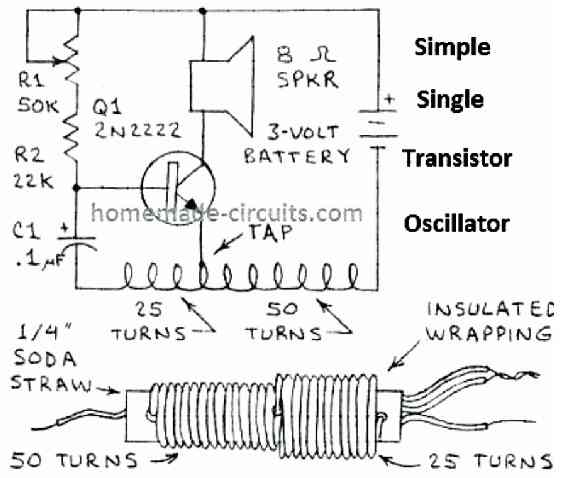
In the above example I will explained an RC based transistor oscillator. The following image explains a simple single transistor, LC based or inductance, capacitance based oscillator circuit module.
The details of the inductor is given in the diagram. Preset R1 can be used for varying the tone frequency from the oscillator.
Metronome Circuit
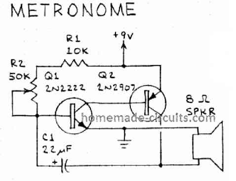
We have already studied a few metronome circuits earlier in the website, simple two transistor metronome circuit is shown below.
Logic Probe
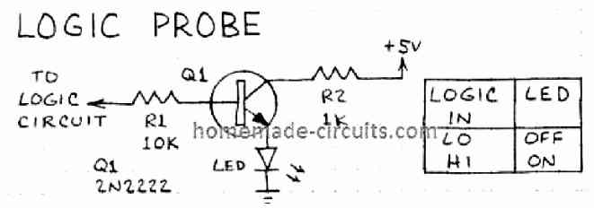
A logic probe circuit is an important piece of equipment for troubleshooting crucial circuit board faults. The unit can be constructed using as minimum as a single transistor and a few resistors. The complete design is shown in the following diagram.
Adjustable Siren Circuit Module
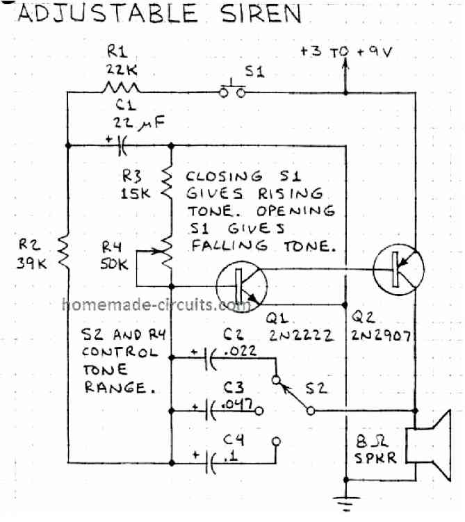
A very useful and powerful siren circuit can be created as depicted in the following diagram. The circuit uses just two transistors for generating a rising and falling type siren sound, which can be toggled using the S1.
The switch S2 selects the frequency range of the tone, higher frequency will generate shriller sound than the lower frequencies. The R4 allows the user to vary the tone even further within the selected range.
White Noise Generator Module
A white noise is a sound frequency which generates a low frequency hissing type of sound, for example the sound which is heard during a constant heavy rainfall, or from an untuned FM station, or from a TV set not connected to a cable connection, a high speed fan etc.
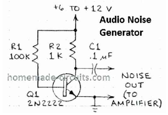
The above single transistor will generate the similar kind of white noise, when its output is connected to a suitable amplifier.
Switch Debouncer Module
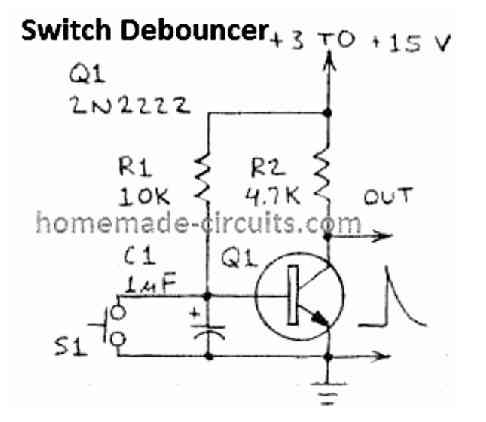
This switch debouncer switch can be used with a push button switch to ensure that the circuit which is being controlled by the push button is never rattled or disturbed due to voltage transients generated while releasing the switch.
When the switch is pressed the output become 0 V instantly and when released the output turns high in slow mode without causing any issues to the attached circuit stages.
Small AM Transmitter Module
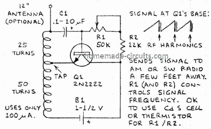
This one transistor, small wireless AM transmitter can send a frequency signal to an AM radio kept some distance away from the unit. The coil can be any ordinary AM/MW antenna coil, also known as loopstick antenna coil.
Frequency Meter Module
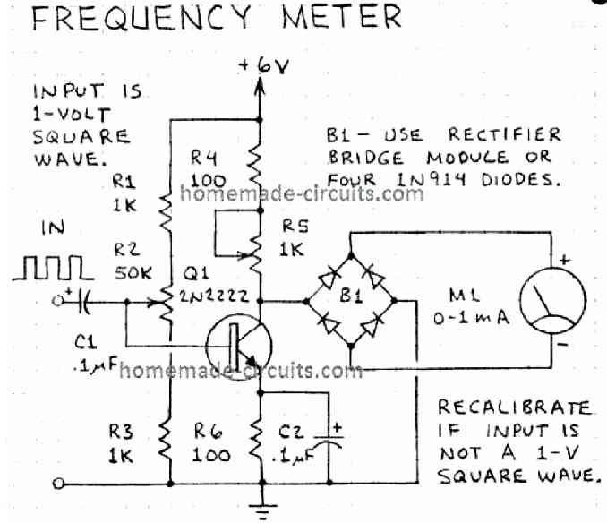
A fairly accurate analogue frequency meter module could be built using the single transistor circuit shown above. The input frequency should be 1 V peak to peak.
The frequency range can be adjusted by using different values for C1, and by setting the R2 pot appropriately.
Pulse Generator Module
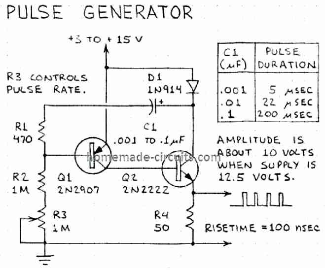
Only a couple of BJTs and a few resistors are required to create a useful pulse generator circuit module as shown in the figure above.
The pulse width can be adjusted using different values for C1, while R3 can be used for adjusting the pulse frequency.
Meter Amplifier Module
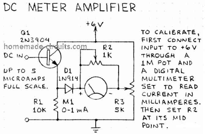
This ammeter amplifier module can be used for measuring extremely small current magnitudes in the range of microamperes, into readable output across a 1 mA ammeter.
Light Activated Flasher Module
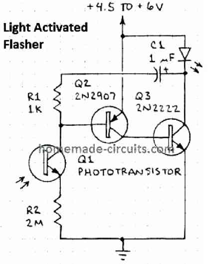
An LED will begin flashing at a specified as soon as an ambient light or an external light is detected over an attached light sensor. The application of this light sensitive flasher may be diverse and very much customizable, depending on user preferences.
Darkness Triggered Flasher
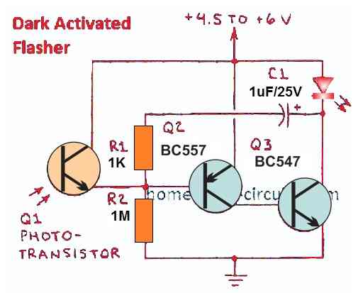
Quite similar, but with opposite effects to the above application, this module will begin flashing an LED as soon as the ambient light level drops to almost darkness, or as set by the R1, R2 potential divider network.
High Power Flasher
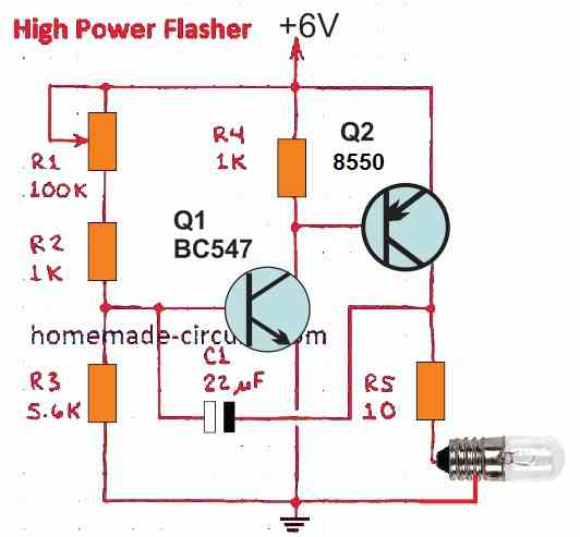
A high power flasher module can be constructed using just a couple of transistor as shown in the above schematic. The unit will blink or flash a connected incandescent or halogen lamp brightly, and the power of this lamp can be upgraded by suitably upgrading the specs of the Q2.
LED Light Transmitter/Receiver Remote Control
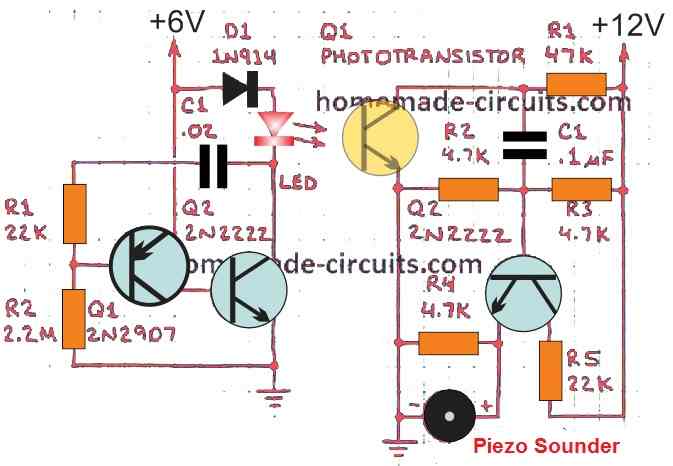
We can notice two circuit modules in the above schematic. The left side module works like a LED frequency transmitter, while the right side module works like the light frequency receiver/detector circuit.
When the transmitter is switched ON and focused on the receiver's light detector Q1, the frequency from the transmitter is detected by the receiver circuit and the attached piezo buzzer begins vibrating at the same frequency. The module can be modified in many different ways, as per specific requirement.
FET Circuit Modules
FET stands for Field Effect Transistors which are considered to be highly efficient transistors compared to the BJTs, in many aspects.
In the following example circuits I will explain about many interesting FET based circuit modules which can be integrated across each other for creating many different innovative circuits, for personalized used and applications.
FET Switch
In the earlier paragraphs I will explained how to use a BJT as a switch, quite similarly, an FET can be also applied like a DC ON/OFF switch.
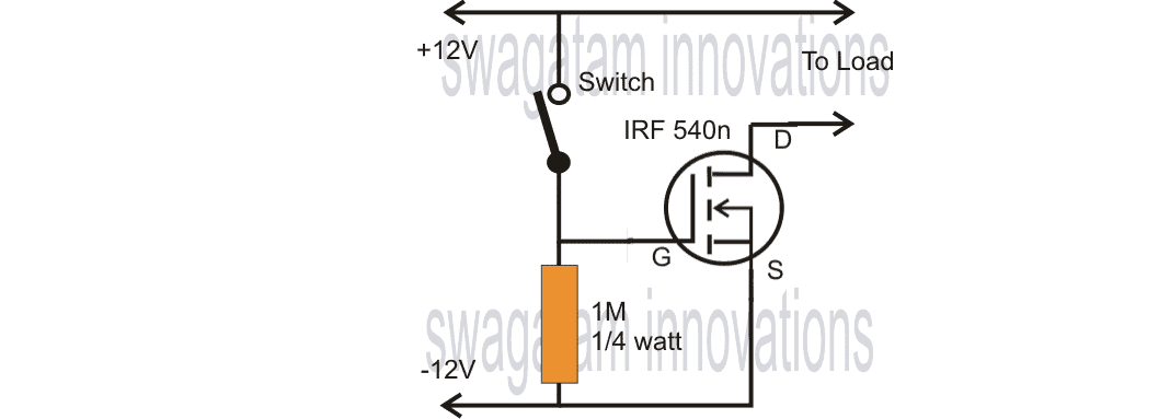
The figure above shows, an FET configured like a switch for toggling an connected load ON/OFF in response to a 12V and 0V input signal at its gate.
Unlike a BJT which can switch ON/OFF an output load in response to an input signal as low as 0.6 V, an FET will do the same but with an input signal of around 9V to 12 V.
However, the 0.6 V for a BJT is current dependent and the current with 0.6 V has to be correspondingly high or low with respect to the load current.
Contrary to this, the input gate drive current for an FET is not load dependent and can be as low as a microampere.
FET Amplifier
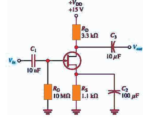
Quite like a BJT, you can also wire an FET for amplifying extremely low current input signals to an amplified high current high voltage output, as indicated the figure above.
High Impedance MIC Amplifier Module
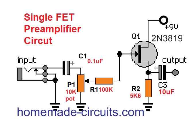
If you are wondering how to use a Field Effect Transistor for constructing a Hi-Z or a High impedance MIC amplifier circuit, then the above explained design might help you in accomplishing the objective.
FET Audo Mixer Module
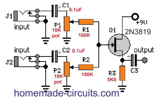
An FET can be also used as an audio signal mixer, as illustrated in the diagram above. Two audio signals fed across points A and B are mixed together by the FET and merged at the output via C4.
FET Delay ON Circuit Module
A reasonably high delay ON timer circuit could be configured using the schematic below.
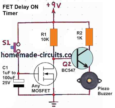
When S1 is pushed ON, the supply gets stored inside the C1 capacitor, and the voltage also switches ON the FET. When S1 is released, the stored charge inside C1 continues to keep the FET ON.
However, the FET being a high impedance input device does not allow the C1 to discharge quickly and therefore the FET remains switched ON for a pretty long time.
In the meantime, as long as the FET Q1 stays ON, the attached BJT Q2 remains switched OFF, due the inverting action of the FET which keeps the Q2 base grounded.
The situation also keeps the buzzer switched OFF. Eventually, and gradually the C1 discharges to a point where the FET is unable to remain switched ON. This reverts the condition at the base of Q1, which now switches ON and activates the connected buzzer alarm.
Delay OFF Timer Module
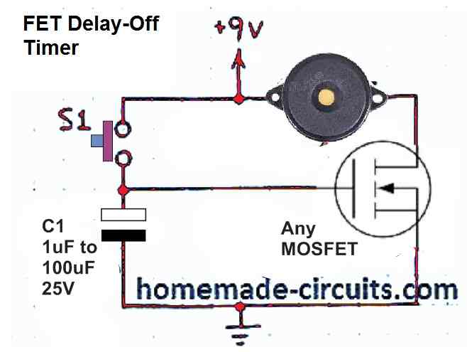
This design does exactly similar to the above concept, except for the inverting BJT stage, which isn't present here.
Due to this reason, the FET acts like a delay OFF timer. Meaning, the output remains ON initially while the capacitor C1 is discharging, and the FET is switched ON, and ultimately when the C1 is fully discharged, the FET switches OFF and the buzzer sounds.
Simple Power Amplifier Module
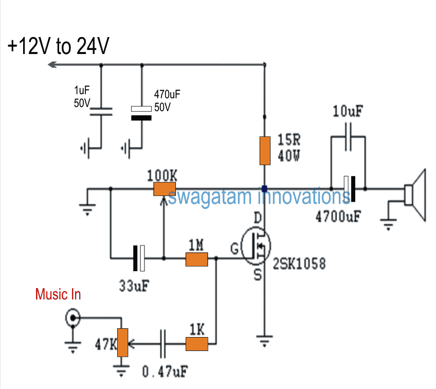
Using just a couple of FETs it may be possible to accomplish a reasonably powerful audio amplifier of around 5 watt or even higher.
Dual Lamp FET Flasher Module
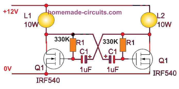
This a very simple FET astable circuit that can be used for alternately flashing two 12V lamps across the two drains of the MOSFETs.
The good aspect of this astable is that the lamps will switch at a well defined sharp ON/OFF rate without any dimming effect or slow fade and rise. The flashing rate could be adjusted through the the two C1s or two R1s..
UJT Oscillator Circuit Modules
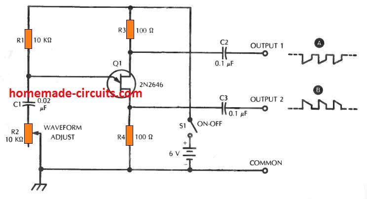
UJT or for Unijunction Transistor, is a special type of transistor which can be configured as an flexible oscillator using an external RC network.
The basic electronic circuit of an electronic UJT based oscillator can be seen in the following diagram. The RC network R1, and C1 determines the frequency output from the UJT device. Increasing the values of either R1 or C1 reduces the frequency rate and vice versa.
UJT Sound Effect Generator Module
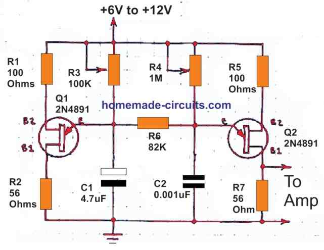
A nice little sound effect generator could be built using a couple UJTs oscillators and by combining their frequencies. The complete circuit diagram is shown below.
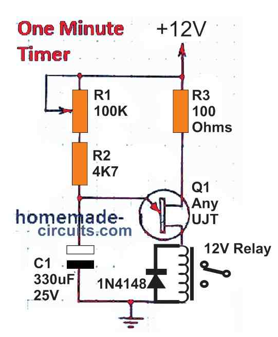
One Minute Timer Module
A very useful one minute ON/OFF delay timer circuit can be built using a single UJT as shown below. It is actually an oscillator circuit using high RC values in order to slow down the ON/OFF frequency rate to 1 minute.
This delay could be further increased by increasing the values of the R1 and C1 components.
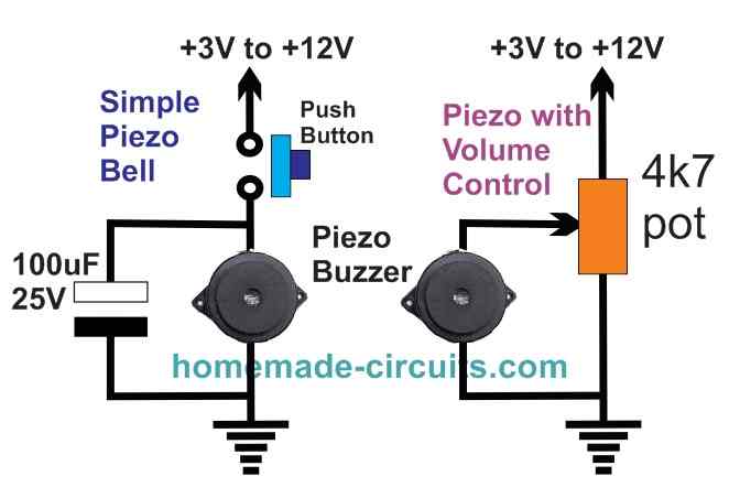
Piezo Transducer Modules
Piezo transducers are specially created devices using piezo material which is sensitive and responsive to electric current.
The piezo material inside a piezo transducer reacts to an electric field causing distortions in its structure which gives rise to vibrations on the device, resulting in the generation of sound.
Conversely, when a calculated mechanical strain is applied on a piezo transducer, it mechanically distorts the piezo material inside the device resulting in the generation of a proportional amount of electric current across the transducer terminals.
When used like DC buzzer, the piezo transducer must be attached with an oscillator for creating the vibration noise output, because these devices can only respond to a frequency.
The image shows a simple piezo buzzer connection with a supply source. This buzzer has an internal oscillator for responding to the supply voltage.
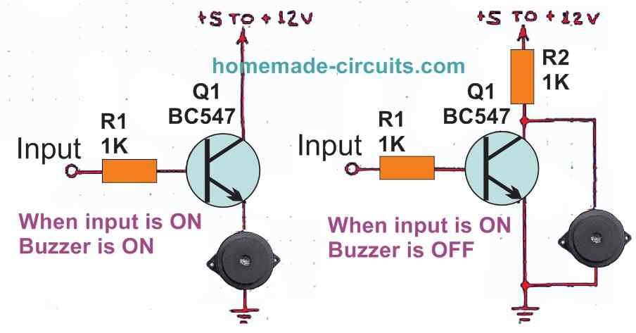
Piezo buzzers can be used for indicating a logic high or low conditions in circuit through the following shown circuit.
Piezo Tone Generator Module
A piezo transducer can be configured to generate continuous low volume tone output the following circuit diagram. The piezo device should be a 3 terminal device.
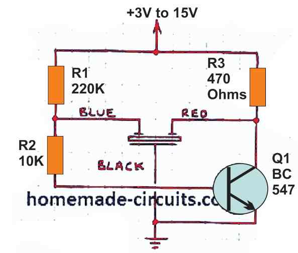
Variable Tone Piezo Buzzer Module
The next basic electronic circuit below shows a couple of buzzer concepts using piezo transducers. The piezo elements are supposed to be 3-wire elements.
The left side diagram shows a resistive design for forcing oscillations in the piezo transducer, while the right side diagram exhibits an inductive concept. The inductor or coil based deign induces the oscillations through feedback spikes.
SCR Circuit Modules
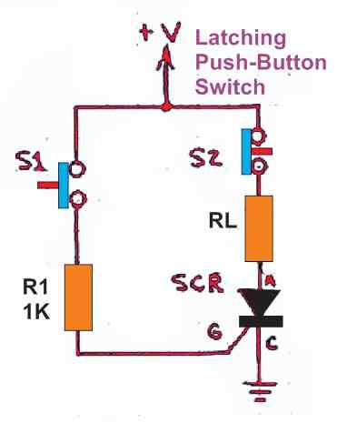
SCRs or thyristors are semiconductor devices which behave like rectifier diodes but facilitate its conduction through an external DC signal input.
However, as per their characteristics, SCRs have the tendency to latch up when the load supply is DC.
The following figure indicates a simple set up which exploits this latching feature of the device to switch ON and OFF a load RL in response to the pressing of the switches S1 and S2. S1 switches ON the load, while S2 switches OFF the load.
Light Activated Relay Module
A simple light activated relay module could be built using an SCR, and a phototransistor, as illustrated in the figure below.
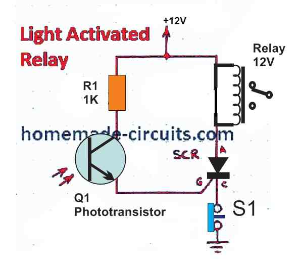
As soon as the light level on the phototransistor exceeds a set triggering threshold level of the SCR, the SCR triggers and latches ON, switch ON the relay.
The latching remains as is until the reset switch S1 is pressed as sufficient darkness, or the power is switched OFF and then ON..
Relaxation Oscillator using SCR Module
A simple relaxation oscillator circuit can be constructed using an SCR and an RC network as exhibited in the diagram below.
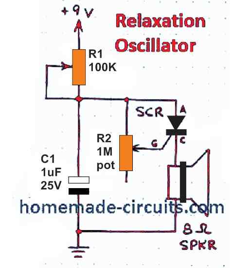
The oscillator frequency will produce a low frequency tone over the connected speaker. The tone frequency of this relaxation oscillator can be adjusted through variable resistor R1, and R2, and also the capacitor C1.
SCR AC Motor Speed Controller Module
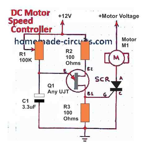
A UJT normally is renowned for its reliable oscillatory functions. However, the same device can be also used with triac for enabling a 0 to full speed control of AC motors.
The resistor R1 functions like a frequency control adjustment for the UJT frequency. This variable frequency output switches the triac at different ON/OFF rates depending on the R1 adjustments.
This variable switching of the triac in turn causes a proportionate amount of variations on the speed of the connected motor.
Triac Gate Buffer Module
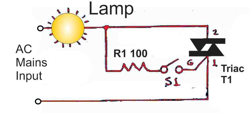
The basic electronic circuit diagram above shows how simply a triac can be switched ON OFF through an ON/OFF switch and also ensure safety to the triac by using the load itself as a buffer stage.
The R1 limits the current to the triac gate, while the load additionally provide the triac gate protection from sudden switch ON transients, and allows the triac to switch ON with a soft start mode.
Triac/UJT Flasher UJT Module
A UJT oscillator can be also implemented as an AC lamp dimmer as shown in the diagram below.
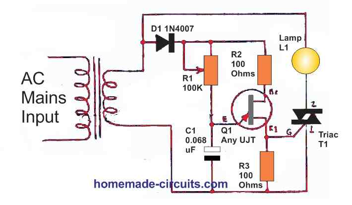
The pot R1 is used for adjusting the oscillating rate or frequency, which in turn determines the ON/OFF switching rate of the triac and the connected lamp.
The switching frequency being too high, the lamp seems to be ON permanently, although it intensity varies due to the average voltage across it varying in accordance with the UJT switching.
Conclusion
In the above sections I will explained many fundamental concepts and theories of electronics and learned how to configure small circuits using diodes, transistors, FETs etc.
There are actually countless more number of circuit modules that can be created using these basic components for implementing any desired circuit idea, as per given specifications.
After getting well versed with all these basic electronic circuit modules, any newcomer in the filed can then learn to integrate these modules across each other for getting numerous other interesting circuits or for accomplishing a specialized circuit application.
If you have any further questions regarding these basics concepts of electronics or regarding how to join these modules for specific needs, please feel free to comment and discuss the topics.
Please how do I calculate the gain and other specifications of the mic preamplifier
Please do have any circuit made with SDT 12v 5A relay
For what circuit application do you need it?
Hi Swagatam;
When we chechk the diode (ie 1N4007) on a multimeter continuity mode then we see the value on the display like 0.574. What that value points out beyond that the diode is not damaged?
Best wishes.
Hi Suat, yes that’s right from one side it must show an open circuit, and from the other side a continuity of around 0.6, which indicates the diode is good.
Hi Swagatam;
My aim is to make ammeter with capacity of 10 amperes. For the purpose I have seen 2 videos. One was about to upgrade multimeter 10 A to 100 A by just simply adding the thicker diameter (about 0.053 inches) copper wire as the shunt resistor. And the other one was about adding ceramic cement body low value high wattage resistors.
Please advise which one is better the thick and long copper wire may be replacement of the resistor or I should prefer the ceramic resistor? In case both of them are acceptable, please advise if copper wire is wound like a coil then it is more effective or no matter? But if resistor is better then I think that four or five of them should be in parallel connected due to overheating and what their wattage should be against the 10 amperes? Please share your comments if possible. Best Wishes
Hi Suat,
I think the ceramic resistor would be better since the copper coil can be too long, thick and bulky.
But I am not exactly sure about the power rating of the resistor. You can start with 50 watts and check the response and then increase it appropriately until the heat is at an acceptable level.
Hi Swagatam;
Referring the above “Potential Divider”
My aim is to make a voltmeter. The circuit IC source voltage is 5 volts. That means if the maximum voltage to be measured was 100 volts DC then it should be 20 times stepped down or if the maximum voltage was 50 volts so then it should be trimmed 10 times not to exceed the IC source voltage. So it is possible to use taht above potential divider. Thanks
P.S. = as sample if input was 100 V then ———-> 5 V= 100 R2 / R1+ R2
the result is 19 R2 = R1
Hi Suat,
Your assumptions are absolutely correct and the concept will work to solve the propose!
Dear Swagatam;
upon your strenghten hand I have decided to measure 220 volts AC too in my circuit. The point at the situation is:
for instant when we use the resistors as R1 5k / R2 500 ohm
OR the resistors as R1 500 ohm / R2 50 ohm
As seen above the ratio of the resistors is 10 both sets of the resistors give the same output result. So what kind of resistor we should prefer in higher values or lower values in our circuit? Best Regards
Hi Suat,
Since AC 220 V in involved try tho make the resistor values as high as possible. The values actually depends on the connected load. Since the voltmeter would be a high impedance load, you can easily increase the resistor values to 500 K, 50 K
I am not sure but neverthless I had intended to use bridge rectifier namely converting AC to DC then trim it abut 45 times. Whereas after sending the message I have hesitated since my IC can perceive / read the internal voltage in the circuit. If we think this as a multimeter then AC 220 volts would be the external input. In that case I am not sure about my Analog Digital Converter input pin reaction? If that might be same as in the BT136 reaction (- pole is common) so that will be nice for me that ADC pin can perceive the external voltage. Thank you very much for the support. Regards
A bridge rectifier will be required, and the ADC will be able to read the external voltage according to me. Hope you are able to solve the problem soon.
Hi Swagatam,
I’ve been searching for a circuit that would use a continuous positive trigger (like an ignition on) that would produce a single one shot pulse, positive output, (to a relay coil) to automatically lock doors upon starting vehicle. I have reviewed several circuits on your site but there are many so if you could direct to one or a modification to one that could satisfy this need?
thanks in advance,
Henry Marotte
Hi Henry,
I think you can try the following circuit for implementing the mentioned application:
https://www.homemade-circuits.com/wp-content/uploads/2022/11/transistor-monostable-with-relay.jpg
The relay contacts could be wired with the window lock ON/OFF circuit.
The relay will momentarily switch ON and then switch OFF each time the ignition switch is activated
thank you Swagatam for the fast reply! I will try this out soon but question here: input trigger is my dc input from ignition on, would supply voltage need to be constant (unswitched) battery feed (needing zero current draw when not in triggered state)?
thanks again
Henry
Hi Henry,
The supply voltage to the circuit must be powered when the ignition trigger is being supplied to the circuit so that the relay can momentarily switch ON and then OFF.
Once the relay is triggered ON/OFF, after that even if the power supply to the circuit is switched OFF it won’t matter.
However ideally the battery could be connected permanently to the circuit.There will be no current drain even if the battery is always attached with the circuit.
Sounds like a winner, i will give it a try soon, thanks again!!
No problem!
The NOR gate LED looks like it’s the wrong way?
You are right, thanks, I have corrected it now!
Hello, I would like to try building the “UJT Sound Effect Generator Module” Circuit, however it appears the 2N4891 unijunction transistor is no longer being manufactured. Is there a substitution that is more readily available? Thanks!
Hello, you can try any other standard UJT which may be available to you.
I landed on your site when looking for simple circuits to teach school kids.Liked the ideas from your collection of circuits.thanks.
In some circuits I notice you did not specify the exact SCR by name.You can name all components and may be say suggested equivalents.
Glad you found the post useful. For the SCR you can try C106.
This tutorial is awesome. Though I don’t understand everything because am a programmer that just want to move to electronic programming but wanted to understand the basic about electronic. I’ll continue to press on and refer back to this article from time to time. Thanks a lot.
I am glad you liked the article. If you have any further questions, do let me know, I’ll be most happy to help!
Thank you very much engineer, I found this article very interesting I will take more time to give it detailed attention before returning to you for any assistance if any. Once again, thank you.
No problem Achia, wish you all the best!
Thank you for the info above ,it was greatly apreciated ,i learned alot in a few hours ,wish you all the best , brilliant place for me ,i am a novice hobbist ,great place thanks once again ,saluti from nicolo Italy.
Thank you very much for visiting here and liking my articles, I truly appreciate your honest feedback
I really like your page, very instructive and didactic, congratulations and continuation of good posts, reminiscent of my university days. Strong hug from Lisbon -Portugal
I am glad you liked my work, and thank you for the encouragement, appreciate your kind feedback!
Hi
Thank you so much for so much information. These circuits are all great I guess, but as a beginner I find them confusing. Seldom does anyone actually explain what is happening so we can learn how the circuits work rather than just that they do. It would be very helpful to see an explanation of what actually happens to the current flowing through when it is ‘plugged in” for the first time. Specifically I am interested now in limiting the current from a power supply (battery) that charges another battery at 2 amps, but I need only .5 amps. Also, I have a power supply whose output is 13.8 V but 5 amps and need to drop that down from 5 amps to 1 amp. Thanks for any help.
Hi, glad you found the article helpful! The flowing of current is all about the shifting of electron charge from the negative terminal of the supply towards the positive terminal. It can be a little difficult to visualize the action without proper graphics or videos.
You can implement current control simply by implementing the concepts presented in these article:
https://www.homemade-circuits.com/?s=current+limit
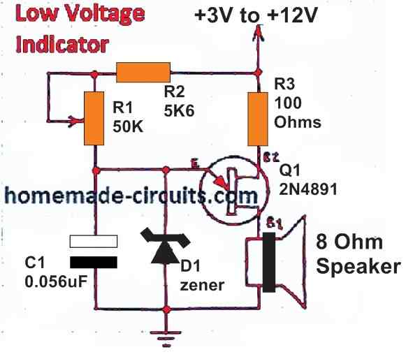
Very interesting, and thorough. You have played, all the necessary of the practical basic electronics, in a single day. It will take me a little time to digest it all, but it is content, very valuable. Thank you for your effort and dedication to help your colleagues in electronics. Just one question, the low voltage detector circuit has a zener, but there is no value next to it. Does that mean that according to the Zener you use, it will be the lower limit of voltage that will activate the alarm?
Thanks in advance.
Thank you very much for liking this article. Appreciate it very much
The UJT will fire or conduct when the voltage at point “E” becomes equal or higher than the voltage across B1…B2…..suppose this voltage is 6V and you want the the alarm to sound at 5 V, then you can use a 5.1 V zener at “E”. This means, when the supply voltage goes below 5V, the zener will stop conduct and the volatge at E will become equal to the voltage across B1…B2, and the UJT will fire sounding the alarm
Thank you so much, keep the good working.
congratulations on the article, it was very good. I learned a lot. Hug from Brazil and success in your career. Health and peace to everyone in your home.
Thank you! Glad you liked it.