A compilation of important assorted transistor simple circuits to build has been included here.
Simple Transistor Circuits for New Hobbyists
Many simple transistor configurations like, rain alarm, delay timer, set reset latch, crystal tester, light sensitive switch and many more have been discussed in this article.
In this compilation of simple transistor circuits (schematics) you will come across many small very important transistor configurations, especially designed and compiled for new budding electronic enthusiasts.
The simple circuits to build (schematics) shown below have very useful applications and are yet easy to build even for new electronic enthusiasts. Let’s begin discussing them:
Adjustable DC power supply:
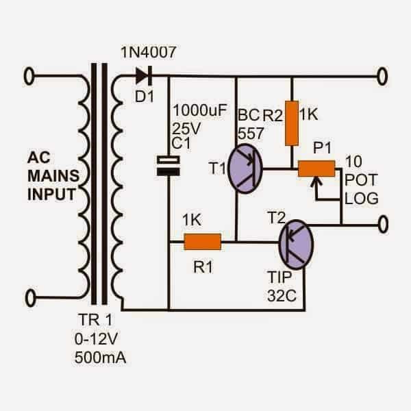
A very nice adjustable power supply unit may be built using just a couple of transistors and a few other passive components.
The circuit provides good load regulation, its maximum current being not more than 500mA, sufficient for most applications.
Highly Recommended: Projects for the Beginners
Rain Alarm
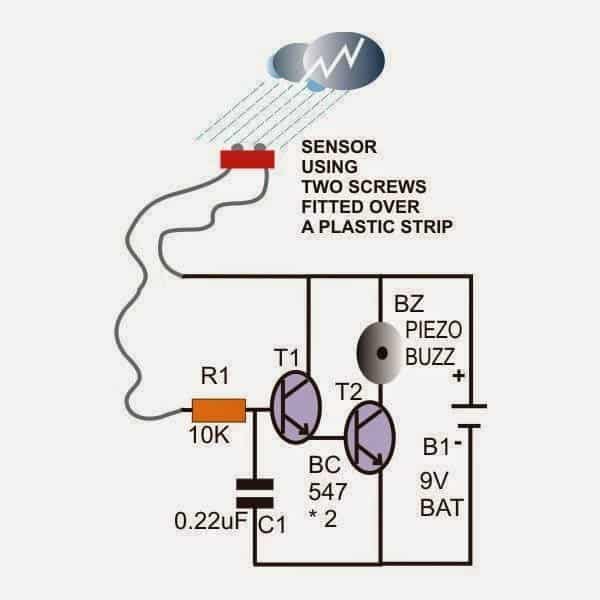
This circuit is built around just two transistors as the main active components.
The configuration is in the form of a standard Darlington pair, which increases its current amplification capacity hugely.
Rain drops or water drops falling and bridging the base with the positive supply is enough to trigger the alarm.
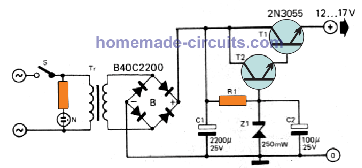
Hum free power supply:
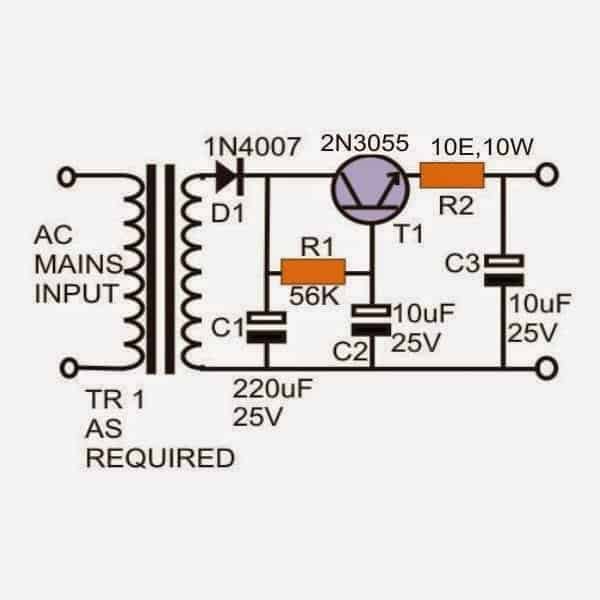
For many audio amplifier circuits hum pick-ups can become a big nuisance, even proper grounding sometimes are unable to rectify this problem.
However, a high-power transistor and a few capacitors when connected as shown can definitely curb this problem and provide the required hum free and ripple free power to the entire circuit.
Set-Reset Latch:
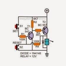
This circuit also utilizes a very few components and will faithfully set and reset the relay and the output load according to the input commands.
Pressing the upper push switch energizes the circuit and the load, whereas it is deactivated by pressing the lower push button.
Simple Delay Timer
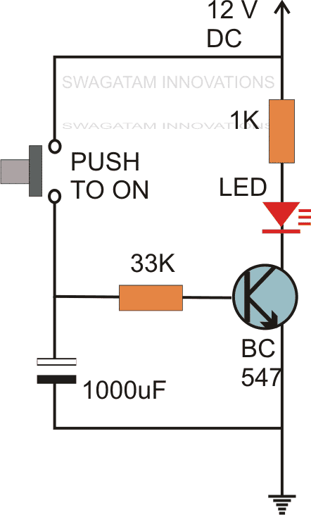
A very simple yet very effective timer circuit can be designed by incorporating just two transistors and other handful of components.
Pressing the push ON switch instantly charges the 1000uF capacitor and switching ON the transistors and the relay.
Even after releasing the switch the circuit holds on the position until C1 is completely discharged. The time delay is determined by the values of R1 and C1. In the present design it’s around 1 minute.
Crystal Tester:
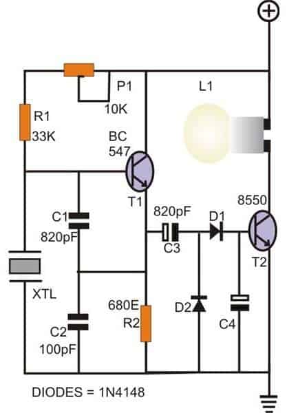
Crystals can be quite unfamiliar components especially with the electronic novices.
The shown circuit is basically a standard Colpitts oscillator incorporating a crystal to initiate its oscillations.
If the connected crystal is a good one, will be indicated through the illuminated bulb, a faulty crystal will keep the lamp shut.
Water Level Warning Indicator:
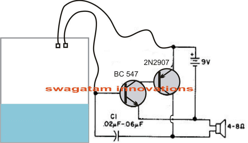
No more peeping and nervous apprehensions with overflowing water tanks.
This circuit will produce a nice little buzzing sound well before you tank spills over.
Nothing can be as simple as this one. Keep watching for more of these little giants, I mean simple circuits to build with huge potentials.
Hand Stability Tester:
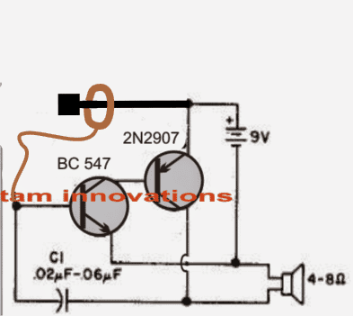
Pretty confident regarding your hand dexterity? The present circuit can definitely challenge you.
Build this circuit and just try sliding a constricted metal ring over the positive supply terminal without touching it.
A buzzing sound from the speaker will entitle you with “antsy hands”.
Light Sensitive Switch:
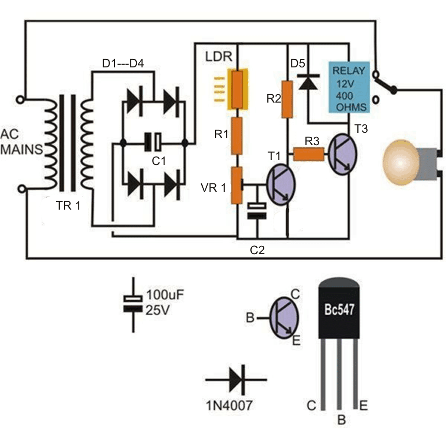
If you are interested to build a low-cost light dependent switch, then this circuit is just for you.
The idea is simple, a presence of light switches OFF the relay and the connected load, absence of light does exactly the opposite.
Need more explanations or help? Just keep posting your valuable comments (comments need moderation, may take time to appear).
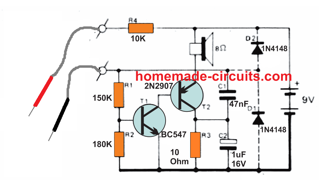
Simple Tester Probe Circuit
Passive testing of an electronic circuit appears pretty straightforward job. All you want is really a Ohm meter.
Sadly, still, working with this type of device for semiconductors is not really advisable. The output currents will probably harm semiconductor junctions.
The tester explained in this write-up is simple to construct and possesses the benefit that a maximum of around 50 µA can only be delivered in the circuit under test.
Therefore it may be used for the majority of standard IC's and semiconductors which includes MOS based elements.
The indication is implemented through a little loudspeaker, to ensure that in the course of testing, it isn't required to keep on referring to the testing device rather than the concentrating on the test points.
The transistor T1 and T2 constitute a basic voltage controlled LF-oscillator, with a loudspeaker working like a load.
The oscillator frequency is formed by C1, R1, R4 and the external resistance between the measuring leads. Resistor R3 is the collector resistance of T2; C2 behaves like a low frequency decoupling of this particular resistor.
As previously mentioned, the tester never will cause any sort of harm to the circuit under check; alternatively, it is best to include diodes D1 and D2 in order that the circuit under test is no way able to counter damage the tester parts.
So long as you don't have an electrical interconnection between the testing prods, the circuit pulls absolutely no current.
Battery-life can then be approximately same as the shelf life of the battery.
Car Fused Tail Lamp Indicator
For those who would like to be assured that the lamps on their automobile are in excellent order, this circuit is probably the remedy.
It is quite basic and offers an honest indication any time a specific light fuses or stops working. With respect to the current drawn by the lamp L, a voltage drop develops around resistance Rx.
This voltage drop should result in being around 400 mV, which can help determine the value of R..
For instance, if it is the tail lights, where a pair of lamps of 10 W 12 V may be parallel, Rx may be worked out as given below:
The current may be expressed as P/V = 20/12 = 1.7 amps
Then Rx can be calculated as V / I = 0.4 / 1.67 = 0.24 Ohms
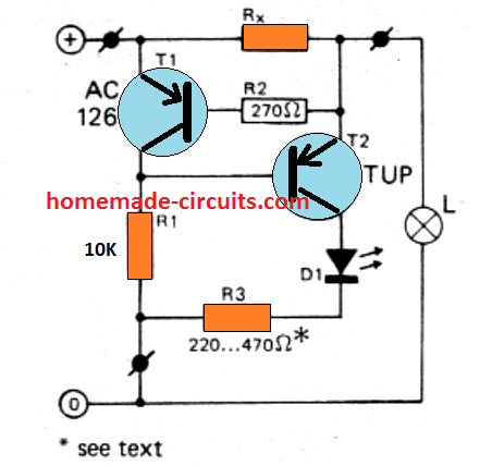
Due to the fact the 400 mV drop develops across RX, T1 is typically switched ON leading to T2 getting cut off.
In case one of the tail lights blows out, the current by means of Rx is lowered by one half, which is 0.84 Amp. The voltage drop across Rx at this point results in being 0.84 x 0.24 = 0.2 V.
This voltage looks appreciably minimal to activate T1, which means this T2 now gets base current via R1, and the LED illuminates.
To get a well-performing indication on lamps failure, it is suggested to make use of a single detector circuit for may be only a couple of lamps.
It is rather allowable, nonetheless, to use a single LED for a number of detectors: D1 and R3 work commonly to all sensors, and the collectors of all T2 transistors may be wired up with each other.
R3 must be 470 Ohms for a 12 V circuitry and 220 Ohms for a 6 V procedure.
Simple Regulated Variable Power Supply
A very simple variable power supply with stabilized output can e built with just a couple of transistors as shown below:
Transistors T1 and T2 form a high current gain Darlington pair for controlling the output voltage.
Since the design is basically an emitter follower, the emitter output follows the base voltage, which means varying the base voltage proportionately varies the emitter output voltage.
R1, along with the zener diode determines the base voltage of the Darlington which in turn provides the equivalent emitter output voltage.
R1 and the zener can be fixed as desired, by selecting the values as per the following date:
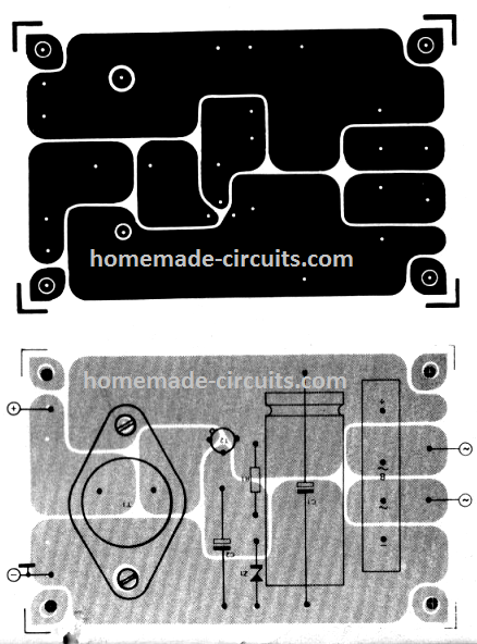
PCB Design for the above transistorized stabilized power supply can be seen in the following figure.
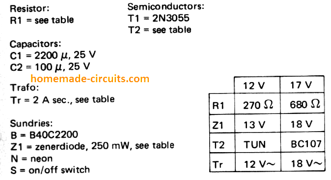
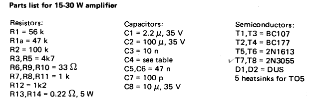
Simple 30 Watt Power Amplifier Circuit
This simple 30 watt fully transistorized amplifier circuit can be used for powering small speaker systems from USB or from mobile, Ipod music sources.
The unit will provide great sounding amplified music output sufficient for any small room.
The distortion level for this 30 watt transistor amplifier circuit is highly reduced and the stability is awesome.
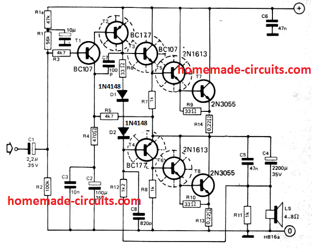
Capacitor C7 is positioned to make up for the phase shift from the output transistors.
The value of R1 is decreased to 56 k, and supplemental decoupling, by means of a 47 k resistor and a I0 µF capacitor are placed in series with high potential side of R1 and power supply positive.
The output impedance is rather minimal, since T5/T7 and T6/T8 work like power darlingtons. The control amplifier stage is effectively competent at delivering the 1-V RMS input voltage.
Due to the reduced input sensitivity, the amplifier provides excellent stability and its level of sensitivity to hum is minimal.
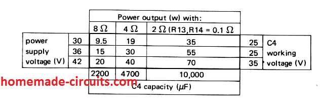
Significant negative feedback through R4 and R5 guarantees reduced distortion. Optimum allowable supply voltage is 42 V.
The power supply circuit must be designed as a stabilized power supply unit for the amplifier.
Besides the heat sinks presented the 3nos 2N3055 transistors needs to be cooled down by clamping them on the metal cabinet using mica insulating washers. The power supply table is designed for stereo.
Electrical Specifications for the 30 watt amplifier circuit is given below:
Full parts list for the the above amplifier circuit
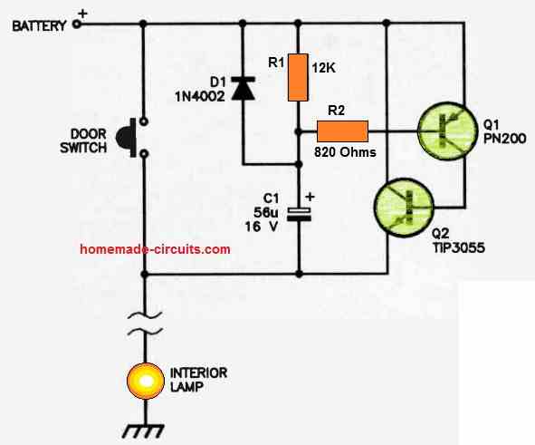
Car Interior Lights Delay OFF
When a vehicle trip begins after sunset, it is helpful to provide a system that can keep the interior lights on sometime after the doors have been locked, making it easy for the drivers to strap seat belts and turn the ignition key.
A simple delay OFF circuit shown below can be used for implementing this function perfectly.
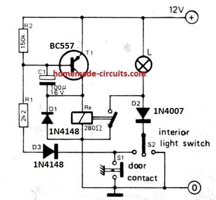
When the doors are shut, the door contact is opened, disconnecting the transistor base from the ground line vi D3.
This breaks the ground bias for the pnp transistor.
However, the relay still holds for sometime due to C1, which allows the BC557 base current to conduct via C1 and the relay coil, until eventually the C1 charges fully and shuts off the transistors and the relay.
7-Segment Display Light controller Circuit
Typical 7 Segment display currents should be restricted to approximately 25 mA, which is normally carried out through series resistors.
When fitted with resistors, the display illumination cannot be any further altered. The circuit demonstrated here, alternatively, supplies the display from an adjustable voltage source built with an emitter follower circuit.
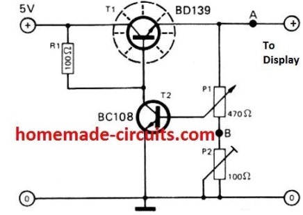
Display's LED illumination varies according to the adjustments of voltage controls P1 (coarse) and P2 (fine), approximately within 0 and 43 volts, the precise setting being somewhat crucial because of the diode characteristic of the LED.
While adjusting the display light, the voltage output is initially fixed at the minimum point, after that steadily increased attain the proper brightness.
The overall current for any 7-digit display must not go over around 1 amp to get a safe and sound segment current of 25 mA (7 segments at 25 mA for 6 digits).
The selection of the series transistor (T1) is determined through its recommended dissipation spec.
Operating Relay with Lower Supply voltage
Once a relay is operated with the rated voltage, it is actually able to hold the activation even if the driving voltage is reduced considerably. With reduced voltage it allows the relay to perform optimally yet save power.
However, the initial voltage has to be close to the relay's specified voltage, otherwise the relay may not activate.
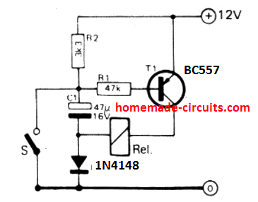
The circuit I have explained below allows the relay to switch ON from a lower than the rated supply by ensuring that at the switch ON the voltage is boosted through a diode/capacitor voltage doubler network.
This boosted voltage provides the relay with the required higher initial supply.
Once the activation is accomplished, the voltage drops to the lower value, enabling the relay to hold and work with a reduced economical power.
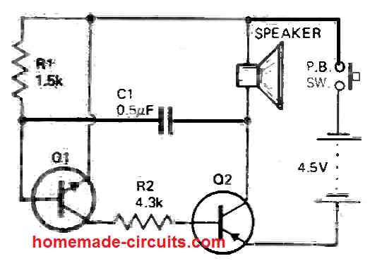
Simple Two Transistor Oscillator
This small experimental two transistor oscillator circuit can easily create audible frequencies within the range between 100 Hz and 2 kHz, operating a little loudspeaker.
The circuit could be driven through 4nos of AA cells or constant 6 volt power supply.
Current specifications for this circuit is determined by the power supply voltage and the impedance of the loudspeaker used and the range normally can be from 10 to 300 mA.
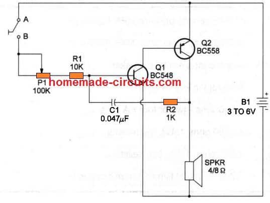
Potentiometer P1 sets the running frequency spectrum which is established inside a wide range of values.
Potentiometers upto 1 M ohms may be tried, transforming the frequency range bottom control to approximately 10 Hz. C1 may likewise be modified, and values between 0.01 uF and 0.22 uF can suit the testing.
Bigger C1 values will generate frequencies in the bottom spectrum of the range.
The circuit works extremely well in applications like alarms, video games, playthings and to get more info regarding transistorized oscillators.
FET Lamp Flasher
The simple lamp flasher circuit is created using a couple of FET's, that are put together like a basic astable multivibrator. These transistors conduct alternately and switch ON/OFF the two lamps.
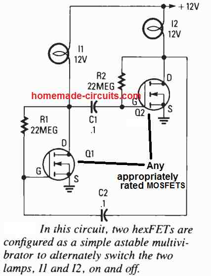
The R/C values shown in the diagram fixes the flashing rate to about 1/3rd Hz.
By simply adjusting either the values of the resistor or the capacitor pretty much any flashing rate can be obtained.
For using higher rated bulbs you can put more number of MOSFTs in parallel, without employing any specific current dependent parts.
The lamps can be a typical 12V to 14V lamp having 6 ohms resistance with cold filament. Whenever 12 volts is utilized, the starting current used by the circuit will be 2 amps.
The same lamp, once switched ON and OFF mode will work using only 200 mA.
Double LED Flasher
The transistor astable, often known as a square-wave generator, is a flexible circuit.
For illustration, the diagram below demonstrates how this can blink a couple of light-emitting diodes (LEDs) once every second.
The time constant values of resistive-capacitive configurations R4 and C1 and R3 and C2 determine the flashing frequency.
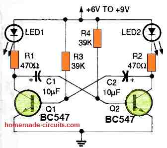
The LEDs are connected in series to the collectors of transistors Q1 and Q2, and both strobe on and off in uniform out-of-phase.
Changing the values of R4 and C1 or R3 and C2 will vary the flashing rate. To convert the circuit into a one-LED flasher, swap one of the LEDs with a short jumper.
9 V Neon Globe Flasher Circuit
Flashing neon globes are employed in numerous applications, but their fairly excessive operating voltage prohibits their normal use in situations where a mains supply cannot be accessed.
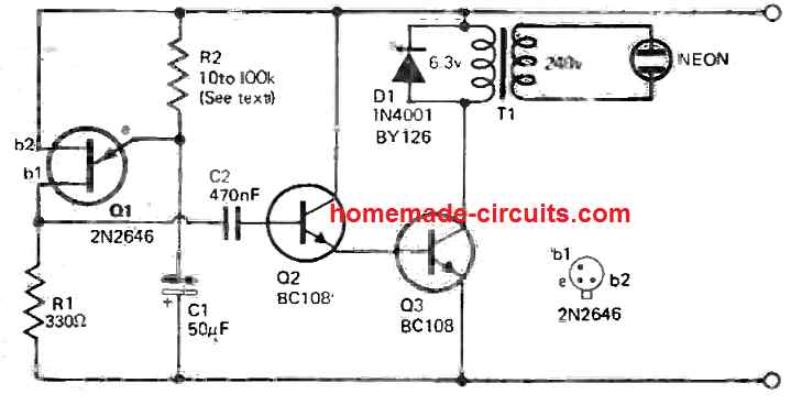
This proposed neon globe flasher circuit circuit makes it possible for neon bulbs to be powered through a low voltage dc supply.
The voltage necessary to fire up the neon tube is achieved through an normal step down transformer 240-6.3V connected in the in the reverse order.
The circuit's battery drain is pretty low which can be in the range of 1 to 2 milliamps with respect to a 9 volt battery supply.
Q1 is a unijunction transistor that is configured to work like a relaxation oscillator. Its functional frequency is established by the R2 -C1 network.
The pulses generated from the UJT Q1 are fed to the transistor Q2 which consequently switches transistor Q3 into saturation.
The sharp increase in the current arising from the 6.3V transformer winding due to Q3 going into saturation mode, forces a high voltage into the secondary winding of the transformer triggering the neon globe to flash.
The diode D1 is positioned to safeguard the transistor coming from high voltage spikes produced due to the inductive switching of the transformer.
Simple Beeper Circuit
This simple beeper circuit is built around an asymmetric multivibrator initialized through a pushbutton. The loudspeaker is a tiny piece having a coil impedance of about 25 to 40 ohms.
You can also use earphones having an impedance of around 500 ohms instead of the recommended speaker.
The resistor R1 can be employed for adjusting the audio frequency range of the beeper.
You can use any silicon, NPN, low frequency, small signal transistor for Q1 for example AC127, BC107, BC108 etc, and for Q2 any PNP transistor such as 8550, 2N2907, BD140 etc can be tried. The battery specifications can be according to the drain current of Q2.
Single Transistor Bass/Treble Circuit
This basic one transistor circuit will deliver roughly 15 dB boost at 100 Hz, or cut at 15 kHz.
A low noise general purpose audio transistor is employed in this simple bass, treble circuit, and the output could be coupled straight into any power amplifier volume control, where the tone control is usually configured.
The gain of this single transistor tone control circuit is close to unity, when measured with the controls adjusted in the "flat" position.
Class A Amplifier
This is actually a Class A amplifier, which means it can drive a load with an impedance more than 65 ohms, for example a small speaker or headset.
A quiescent current of roughly 20 milliamperes is drawn by the amplifier. Conversely, by raising the value of R3, this drain could be decreased.
The transistors Q1 and Q2 are set up as common-emitter amplifiers, with Q1's output linked directly to Q2's input.
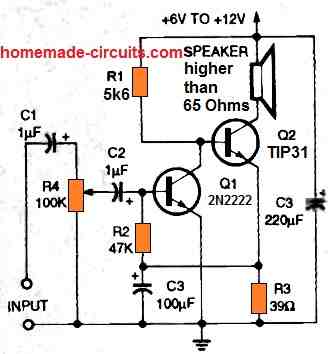
The total voltage gain of this circuit is around 80 dB. Observe how capacitor C3 decouples resistor R3, Q2's emitter load, such that the Q2 emitter voltage follows the average collector voltage of Q1.
Using R2, the base bias for Q1 is obtained from the emitter of Q2. Negative DC feedback stabilizes the bias in this setup. The loudness of the circuit is controlled by the input potentiometer R4.
Noise Limiter Circuit
Audio noise may be irritating, specifically when attempting to listen to a poor broadcast channel.
You could discover that the undesired background noise totally drowns out the broadcast signal, rendering it unusable.
The transistorized noise limiter circuit depicted in the diagram below can be used to solve this problem.
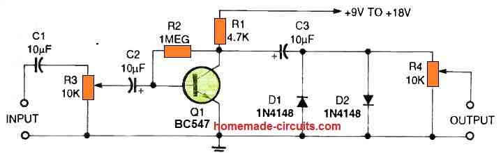
Using potentiometer R3, both the signal and the noise are sent to amplifier Q1 in this circuit.
These waveforms are amplified identically by transistor Q1, however diodes D1 and D2 restrict the peak-to-peak output fluctuation of Q1 to around 1.2 volts.
The noise peaks would not surpass the signal output if R3 is set so that the signal output is increased to this peak level.
As a result, the signal strength might be more clear and understandable.
Beat Frequency Oscillator BFO
Inductance-capacitance (LC) oscillators have a wide range of applications in test equipment and practical circuits.
A local oscillator, sometimes known as a beat frequency oscillator or BFO, can be built using a single BJ, as shown in the figure below.
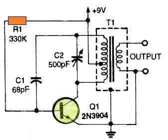
The collector load of transistor Q1 is a tweaked 465 kHz intermediate frequency transformer, which is arranged as a traditional Hartley oscillator.
When the transformer's inbuilt tuning capacitor is removed, variable capacitor C1 converts into the variable-frequency oscillator's tuning control.
The output frequency may be set anywhere between 465 kHz and 1.7 MHz.
When a radio capable of detecting broadcasting range frequencies is positioned close to the signal generation circuit, this would catch the oscillation frequency.
A beat note could be audible if the signal generator is adjusted to the radio's intermediate frequency. Continuous-wave or single-sideband broadcasts could be easily received as a result.
Simplest Metal Detector
The following single transistor circuit diagram is a variation of the aforementioned BFO idea, however it does not include a transformer secondary.
When combined with a nearby radio receiver acting as a detector and amplifier, the circuit transforms into a basic metal object finder.
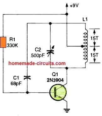
Oscillator coil L1 is constructed by firmly wrapping 30 turns of wire on a 3 to 4-inch diameter plastic base or bobbin.
When a three-wire cable connects it to the circuit, it converts into a search head or sensing coil.
When you're using the circuit as a traditional ground-sweeping metal detector, the search head or sensor may be put at the bottom end of a long wooden or plastic pole.
Detecting buried riches or army mines with at a minimum of some metal pieces could be done using identical circuits.
If you wish to detect metal pipes or wires that are concealed by brick, wood, or plastered walls, the entire circuit could be stored in a portable box.
The existence of a metal body which will conflict with coil L1's electromagnetic field is required for the object finder circuit to work.
Both the inductance value of L1 and the frequency of the field are affected by the intruding object.
A battery-powered portable broadcast band radio brought closer to the locator circuit may pinpoint the location of the metal item. It detects the variation in frequency and emits a loud shriek.
To listen to a low-frequency rhythm or flutter from the radio's speaker, initially set the radio to a local station.
Next tweak C1 to observe a low-frequency beat or chirp from the radio's speaker.
If the locating circuit is positioned closed to the concealed metal object, the beat note will change drastically.
9V to 300V Converter using a Single Transistor
Yet again a Hartley oscillator is employed as a DC-to-DC converter in the next figure below. It has the ability to convert a 9-volt battery's output to 300-volts DC.
T1 is a transformer that converts 9 -0- -9 volts to 250 volts. The oscillator's inductance (L) is formed by its primary.
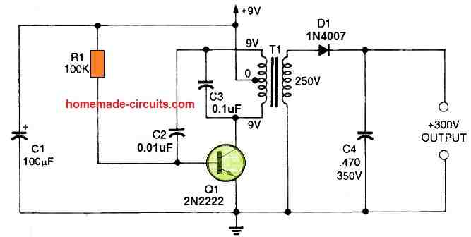
At T1's secondary, the 9V supply is stepped up to a maximum of roughly 350 volts. Half-wave rectifier diode D1 rectifies this waveform and charges capacitor C4.
With a load current of several milliamperes, the output drops to roughly 300 volts with a permanent load.
Warning: Because C4 is not permanently loaded, it can store and discharge a severe but nonlethal shock to any newbie.
Logic Probe
Our next device is a two-transistor logic probe, also known as a positive voltage sensor. When attached to a positive potential, sounds a buzzer and illuminates an LED.
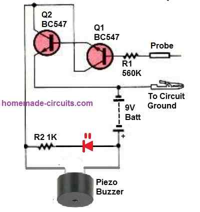
The Darlington connection between transistors Q1 and Q2 provides the circuit an extremely high input impedance.
The LED and piezo buzzer are powered by the common collector output of the transistors.
The transistors switch on and provide visible and audible output signals as soon as the probe detects a positive voltage higher than about 1.5 volts (logic high).
For the logic probe to function, the probe's negative lead is necessary to be attached to the common or negative supply rail of the PCB that is being tested.
Light Operated Music Generator Circuit
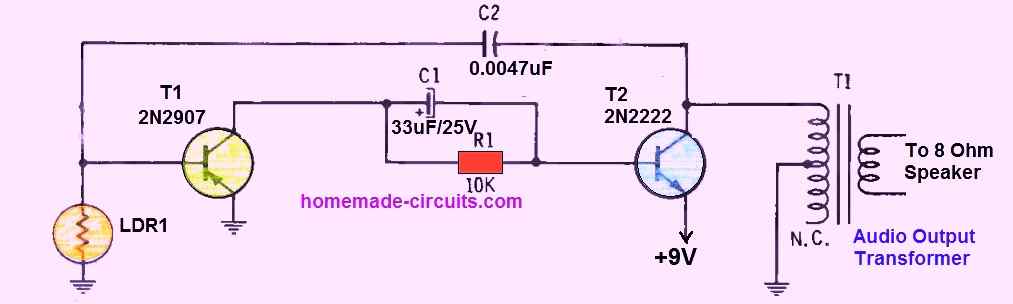
This strange transistorized device, sometimes known as an audio light detector, transforms light energy into melody. Simply placing it close to a bulb causes the speaker to start emitting tones right away.
Simple hand motions between the background light and the LDR can be used to make music. This method of severing the light rays alters the amount of light that reaches the sensitive LDR, which in turn generates various audio tones.
With a bit of effort, you will quickly be capable of generating well-known tunes from the circuit.
This oscillator is not truly a light detected oscillator. For powering the speaker and transistors, it does comes with a built-in 9-volt battery. The LDR just changes the bias resistance of transistor T1.
The end result is a device that generates a diverse variety of sounds while maintaining the same intensity.
By the way, you'll discover that the generated tone gets higher as the light source becomes stronger (for instance, in a direct sunshine). The best technique to diffuse light is to let it travel across your fingers.
Universal Signal Generator
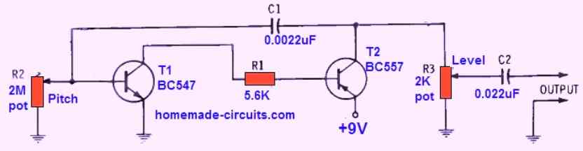
Do you need a practical yet affordable transistorized audio signal generator to test your audio projects? Perhaps you would want to get some of your broken radios and amplifiers operating again?
Whatever your needs, this handy small signal generator has all the functionality available in the more costly commercial models, making it the perfect tool for general troubleshooting.
This straightforward transistor-based signal generator simply requires two control potentiometer: R2 to alter the output tone or audio frequency, and R3 to function as a "level" adjustment pot.
It may be constructed within a compact aluminum Mini-box. As soon as it's finished, you may tune your signal generator by just comparing its output against that of a verified source, like another generator.
Echo Effect Generator Circuit
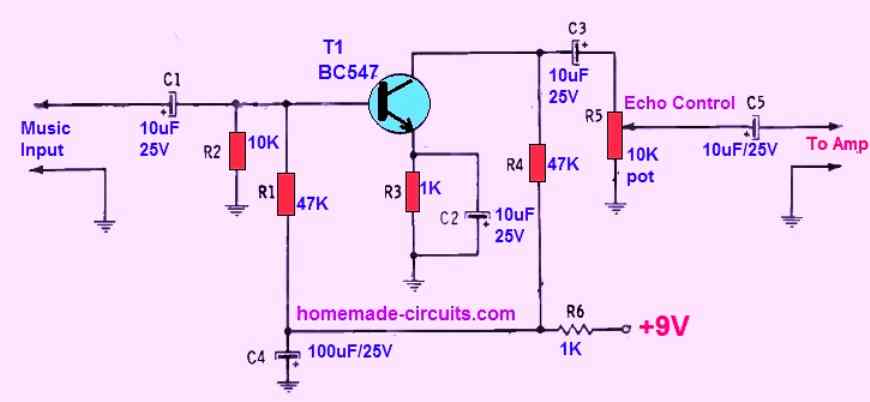
This single transistor design will enhance any low music level input with interesting echo effects.
The various capacitors installed around the transistor collector and emitter leads ensure that the transistor does not conduct instantaneously rather conducts with a softly with a reverb kind of effect.
The pot control can be tweaked to adjust the echo effect to the desired levels.
Constant Current Source
Our next transistor use will be in a circuit with a continuous current source. The 6 volt Zener diode, D1, controls the base voltage of the transistor in this circuit, while the magnitude of R2 controls the emitter current.
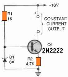
The constant current value is obtained by dividing the Zener voltage by R2's resistance.
Practically speaking, the current that flows through the transistor's collector circuit is identical to the current that flows through its emitter circuit.
Simplest BJT Amplifier
The next transistor circuit below depicts essentially the easiest common-emitter audio amplifier circuit you could put together.
Although a BC547 junction transistor is used in the circuit's illustration for Q1, almost any BJT will function just fine.
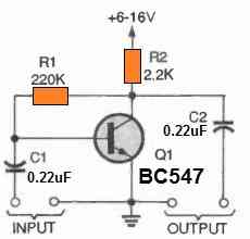
The circuit's base bias current is fed in a negative feedback manner from the collector, which is the biasing approach utilized in the circuit.
As a result, transistors with a wide range of gain can produce good results.
To achieve optimal results, you may want to adjust R1's value if you decide to employ an alternative transistor for Q1.
Hookup a voltmeter to the transistor's collector and circuit ground to determine the right value for R1. After this, choose a value for R1 that results in a meter reading that is half the supply voltage.
Simple Transistorized Voltage Regulator Circuit
This voltage regulation circuit is designed to generate a 6V output from a 9V input provided by a battery. It is capable of maintaining the output voltage even when the input drops as low as 6.5V.
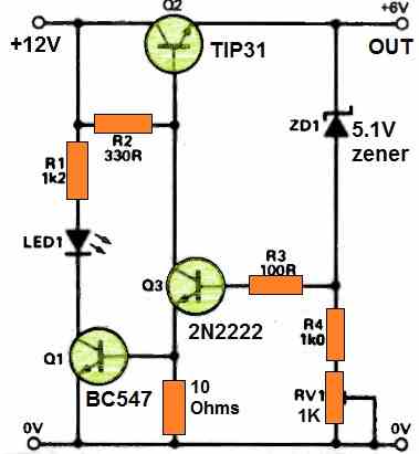
The circuit can deliver a maximum current of 180mA. Upon powering the circuit, transistor Q2 is activated through resistor R2.
Transistor Q3 controls transistor Q2's operation to ensure appropriate voltage levels across components like ZD1 and the base-emitter junctions of Q2, thereby controlling supply voltages and output currents.
The output voltage can be fine-tuned within the range of 5.7V to 6.7V using variable resistor RV1, as the voltage across the Zener diode (zener voltage) depends on the current flowing through it.
When Q1 is turned on, it illuminates LED1, indicating the presence of a stable regulated output.
Should the supply voltage drop below 6.5V, components Q1 and Q3 deactivate, causing LED1 to go off.
Additionally, Q2 is strongly activated, connecting the output to the supply with minimal power dissipation in the idle regulator.
Spy Bug FM Transmitter Circuit
This circuit is designed to work like a small yet powerful FM 'bug', transmitting on FM bands, somewhere between 88 and 108MHz. This circuit can be no doubt completely illegal to operate without appropriate permissions..
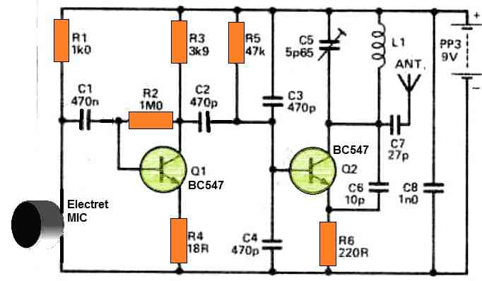
In this spy bug transmitter circuit, the microphone signals undergo amplification through transistor Q1. To reduce sensitivity, you can omit components R2, R3, R4, C2, and Q1.
Transistor Q2 functions as an oscillator grounded to the base, with its frequency determined by C5 and L1.
Feedback for Q2 is obtained from C6, which is an important component (approximately 10pF is recommended for stable oscillation).
When audio signals reach BJT Q2, they cause a slight shift in the center frequency of oscillation, resulting in the desired FM effect.
The microphone used is an electret type with a built-in amplifier.
L1 inductor consists of five turns of 20-gauge wire with a 1/2-inch diameter.
For the spy bug circuit antenna, five inches of insulated wire will suffice. C5 is adjustable to fine-tune the transmitted frequency.
1.5 V LED Flasher Circuit using Transistors
Operating LEDs on a 1.5 V battery can be challenging due to the typical forward voltage requirements of LEDs falling between 1.6 and 2.3 volts.
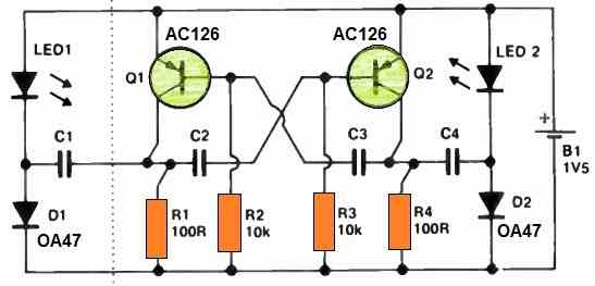
This above design introduces a solution in the form of an astable multivibrator and voltage doubler circuit, effectively amplifying the voltage supplied to the LEDs.
To maintain the appearance of a continuous LED glow, it is advisable to use 47uF capacitors for both C1 and C4, along with 10uF capacitors for C2 and C3.
If you prefer an alternating LED flashing pattern, opt for approximately 100uF capacitors for C2 and C3, with C3-C4 being roughly 10 times that value.
When operating a single LED, you can exclude LED1, D1, and C1 from the circuit.
Simple High Input Impedance Transistor Buffer Circuit
This uncomplicated transistor buffer circuit offers a medium-to-high input impedance and maintains an exceptionally low output impedance.
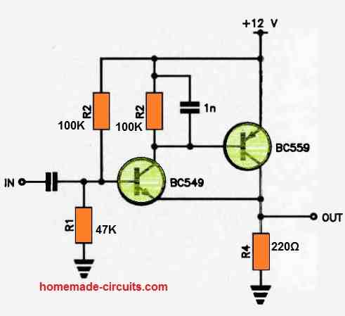
The NPN-PNP combination is directly connected, forming common-emitter stages.
This configuration results in a notably high input impedance at the BC543's base and an exceptionally low output impedance due to the shared feedback path through R4.
To enhance the bandwidth, a 1nF capacitor is included. Depending on the specific application, the input capacitor can be selected within a range of 10nF to 1uF or thereabouts.
The upper-frequency response extends into the megahertz (MHz) range.
Single Transistor Preamp to Convert a speaker into a MIC
Constructing this single BJT preamp circuit allows for the ingenious use of a compact 50 mm speaker as a microphone.
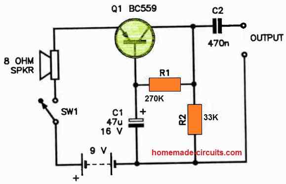
In this setup, transistor Q1 is configured as a grounded-base amplifier, with the speaker positioned in the emitter. The output is then coupled capacitively from the collector.
The results are quite impressive, demonstrating the circuit's effectiveness.
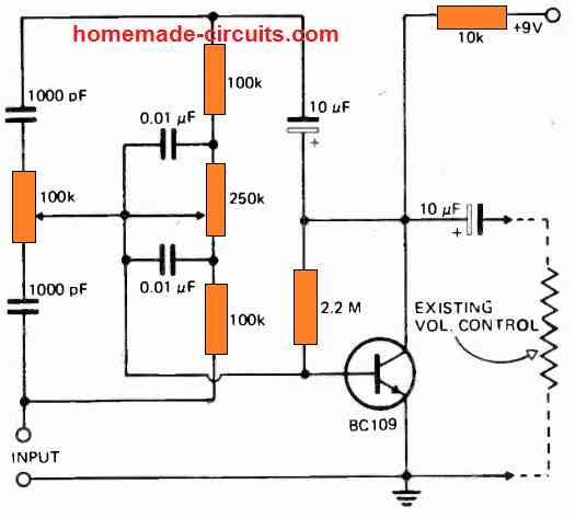
Automatic Volume Control Circuit using a Single BJT
This circuit can be integrated into various solid-state audio power amplifier stages, such as those found in a receiver, to introduce an automatic volume control mechanism that ensures a consistent audio output level.
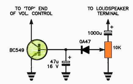
The signal from the loudspeaker is tapped using a 1000pF capacitor and a 10k potentiometer, then rectified by an 0A47 diode.
The resulting DC voltage is applied to the transistor's base. This rectified audio signal adjusts in tandem with changes in the audio's loudness.
Consequently, it alters the transistor's base current, which, in turn, modifies its collector resistance.
This modification effectively shunts the volume control more with louder signals and less with softer ones. The outcome is the maintenance of a more stable audio level.
Additionally, a 47pF capacitor introduces a slight delay, preventing abrupt volume increases when loud passages follow softer ones.
Single BJT Phase Shift Circuit
You can have a lot of fun experimenting with audio phase-shift effects using this circuit.
Q1 serves as a phase splitter, with the input signal connected to its base.
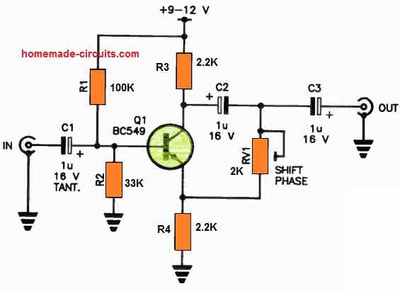
The two outputs are interconnected through C2 and RV1, and you can access the output signal at their junction through C3.
By adjusting RV1, you can shift the phase of the audio signal back and forth, creating interesting effects.
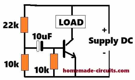
Car Interior Lights Delayed Switch OFF
By connecting this straightforward circuit in parallel with your vehicle's interior light, you can extend its illumination for approximately 20 seconds after you open and close the door. This feature proves quite useful, especially when searching for your keys in the dark.
Here's how it works: When you open the car door, the door switch closes, causing the interior light to activate. This action effectively short-circuits the timer circuit.
As you subsequently close the door, capacitor C1 gradually charges up, delivering base current to transistor Q1.
This, in turn, activates Q2, ensuring a continuous flow of current to keep the lamp illuminated.
Once capacitor C1 has reached a sufficient charge, the current through Q1 becomes insufficient, causing Q2 to turn off and, consequently, switching off the interior lamp.
Simple Two Transistor Filament Lamp Flasher
This simple two transistor oscillator circuit serves as an excellent supplementary continuous lamp flasher for your current flashlight setup.
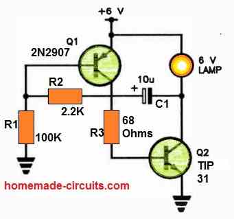
The PNP-NPN transistor combination is configured as a non-inverting amplifier, featuring feedback from the output to the input through a 10uF capacitor and a 2k2 resistor.
This configuration generates oscillations at approximately one Hertz, resulting in a slow, intermittent illumination of the lamp.
When using a 12 V lamp, it's essential to provide it with a 12 V battery for optimal performance.


Questions & Answers
hello Sir. I am beginning to plan for my upcoming project and was hoping for some guidance. We are required to use only discrete components for this . Could you please suggest some interesting project ideas or topics when you have a moment? Thank you for your time.
Hi Nate,
Sure, I will provide all the necessary guidance to ensure you succeed with the projects.
Can you please tell me what type of circuits do you prefer to build, please tell me some examples…I will try my best to get them for you..
we are required to build any circuit using discrete components . could you please recommend me something that is easy to build . examples could be something like metal detectors etc
Sure, for a metal detector, you can probably try the first circuit from this article:
https://www.homemade-circuits.com/how-to-make-simple-metal-detector/
You will require headphones for this, to identify the hidden metal…
hello sir ,
whats your opinion on automatic irrigation system. Do you think it would be an easy build using just discrete components , If so can you share it with me. Also sir, would you by any chance know how to create a temperature controlled smart fan without using an ic.
Hi Nate,
A timer based automatic irrigation system can be built using a couple ICs like IC 555 and IC 4017.
For temperature controlled fan, you can refer to the following articles:
https://www.homemade-circuits.com/automatic-temperatureclimate-controlled/
https://www.homemade-circuits.com/automatic-temperature-regulator-circuit/
Great projects! I am looking through these as I am trying to design a simple power circuit to drop a 4s lithium battery pack to a voltage that most 12v off the shelf inverters can handle which seems to be around 15v to 11v. The complication comes from the ~250w of power that I would like to supply to the inverters. My batteries can handle it, but I don’t know how to properly cap the voltage at that high current.
Someone suggested I try a zener at 15v which led me down the zener + transistor, probably a darlington pair as you have used. I mostly understand how that circuit works, but I don’t know which parts to get for the high current portion of the circuit.
Is there any way we could get a project that shows a voltage limiter that can handle a 2v drop at 20a?
Thanks for your question.
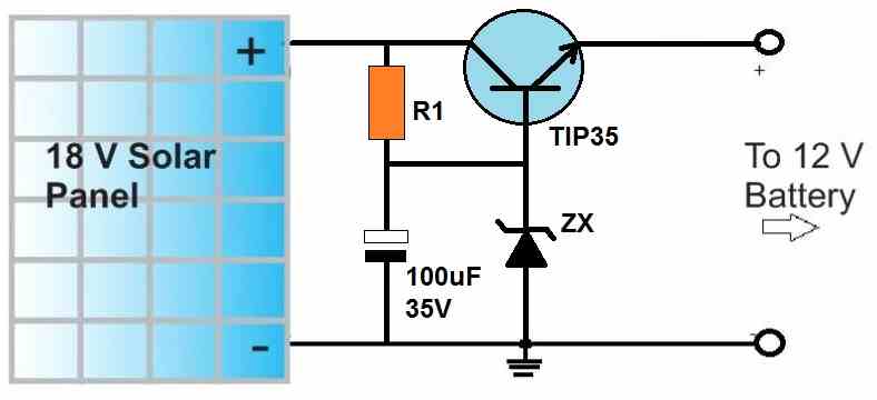
Yes, the 15V can be dropped to 12V at a current of 20 amps using a transistor/zener emitter follower regulator as shown in the following link:
Replace the solar panel with your 4s li-ion battery.
Replace the TIP35 BJT with the following BJT:
https://www.homemade-circuits.com/50-amp-transistor-mj11032-mj11033-datasheet-pinout/
Replace the zener diode with a single 1N4007 diode, with its cathode towards the ground. so the 0.6V drop by this diode plus the internal 1.2V drop of the Darlington will cause the emitter output of the transistor to be around 16 – 1.8 = 14.2V, if you feel this is still high, you can add two 1N4007 in series in place of the zener diode…
Let me know if you have any further questions or doubts?
Good evening.
I would like to ask for a Bluetooth circuit that I can connect to my cellphone.
Thank you in advance
Hi, please provide more details regarding the circuit objective, I will try to figure it out for you…
Hi,
I have a simple circuit using a relay and a red and a green LED to remotely show if a garage door is open or shut. (Shut = green, open = red).
The trigger mechanism is a magnetic switch on the door. (NO or NC).
This works fine, but the relay is constantly energized when the door is open. (The relay is SPDT).
i’m trying to do this with a transistor switch / circuit that will operate on a change of state (mag switch open or closed). The problem I have is that my “trigger” is not a pulse, but either a constant logic 1 or 0. Once the door closes, the state remains unchanged until the next door movement.
I’ve looked at “change of state” circuits, but they seem only to operate on a pulse input.
I guess I could use a transistor / capacitor arrangement to give a pulsed input, but then it would need to operate again once the state of the mag switch changes.
Is this feasible, or should I just stick with the relay, and limit the current once it has energized?
Thank you for any advice.
(I am an old school hobbyist who is trying to go digital!)
Allan
If I am right, I guess your relay circuit converts each opening and closing operation of the gate into a pulse which operates a flip-flop to switch the relay alternately ON/OFF.
What is the main function of the relay? Is it to switch the LEDs only, or to operate some other heavier load?
If the relay is not doing anything except switching the LEDs, you can perhaps try removing the relay, and configure the LEDs with the output of the flip-flop of your relay circuit.
Hello sir, please how can I make a push button on/off circuit with bjt or get rather than relay. Thanks
Hello Seun, what kind of load do you want to control, if it is an AC load you will need a relay or a triac.
No sir, it is DC load, please how can it be made.
Ok, you can use the following setup:
Also make sure to connect a 10k resistor from base to ground, the series base resistor value will depend on the collector load.
Thanks for this sir. I have a push button circuit that when activated triggers the relay on and deactivates in second without manual button pressing.
I now need a circuit which will not use relay but fet, or bjt, activating and deactivating the fet, operating as automatic push button.
Hello Seun, the previous circuit which I gave you will do exactly the same, when the push button is pressed the BJT will activate, and as soon as the push button is released the BJT will switch OFF.
Thanks sir, I have an auto push on button circuit which uses 100uf, 47k resistor and a relay with 12v supply.
But now, is it possible to have same circuit replacing the relay with btj or FET
Can you please describe the circuit connections or show the schematic link.
Thanks sir, the cap and the resistor are in parallel, then connect in series to the anode side of the relay at one end. Connect the + end of the cap to the 12-ve supply. then the cathode side of the relay to 12+ve of the voltage. When the switch is on the relay is activated for a split second and deactivated
Seun, where is the push button in your circuit?
So sorry for the confusion, I meant I need a circuit that will momentarily activate either bjt or fet, instead a relay as described above.
Should there be a push button or without push button?
No sir, I don’t want push button to be there
Seun, you can try the following diagram:
Sir
My self Dibakar panda technical Asst. Electronics and communication dept.Kiit deemed to be university
now in our branch need one lab setup as guide by nep gov of India that skill development of students about electronics circuit .
So request you please help me what kind of experiment and circuit diagram please send me me email address
Thanking you sir
Dibakar Panda
Hi Dibakar,
First the students must study regarding how the various electronic components are designed to work, and only then they must be encouraged to build small projects.
There are so many small projects to build, it will depend on your choice from where to start.
If you have any ideas or suggestions, let me know, I will guide you accordingly.
Great website and thanks for sharing. I am retired from electronics and I usually cope OK (in the end) but I do have one very ticklish problem with a faux pendulum clock circuit. It has baffled me since it arrived from a charity shop. I swapped the only transistor (marked BC549 & checked hfe over 400) for same type and although reluctant it did run, stopping every couple of weeks. A persistent slow lateral shake would get it started as though it needed to charge something up. Now I can’t verify the components of the original but I have tried many transistors (all NPN) including a germanium with over 400hfe gain. Last time change I lifted it up to move the time on 1 hour to BST. It stopped and has never run again.
I have swapped the Caps (which check OK anyway), washed the PCB, and tested the resistors. Both the coils read around 800Rdc (and I have tried reversing one for phase). NBG! Do you want me to check the inductance? It will be difficult with such fine wire lead-outs. Could it be a shorted turn? Come on humour me and say something smart! The quartz clock section runs so don’t tell me the time. You want photos? Can I post pics here? Nope it appears not…… So brief description: Magnet on swinging pendulum passes a bobbin wound with isolated coils. The sense coil generates a pulse into the base of emitter follower transistor and pulses the drive coil which is its emitter load. This imparts a small impulse to keep the pendulum swinging. (Its less than 2″ long). There is a small pulse on a scope but I don’t know what to expect.
Well you did encourage me to ask….! Best regards, Berry G.
Thank you very much for visiting this site and for your detailed explanation. However, honestly I am finding it difficult to figure out the issue. I have no idea about this configuration.
It seems like some kind of perpetual machine since it does not involve a battery, that’s strange indeed.
I hope somebody else here will be able to understand the issue and share a suggestion.
Hi Swagatam;
When transistors are being used if we place the load either emitter side or collector side please advise the result are same for both situation or one is better than other? Thanks and regards.
Hi Suat,
when you connect the load on the emitter, the transistor works like emitter follower. Meaning the emitter voltage will be exactly equal to the base voltage minus 0.6V. Suppose if the collector voltage is 12V, and the base voltage is 6V, then the emitter voltage will not be 12V, rather it would be 6 – 0.6 = 5.4 V.
But the when the load is connected on the collector side, then the load will get the full 12V as long as the base voltage is above 0.6 V.
The above connections depends on the circuit application, how you want the load to behave.
Greetings again,
about the “9 V Neon Globe Flasher Circuit”,
under R2 it says “see text” how do I decide its value from the given range “10to100k”?
I would like to use a transformer that is rated at 120v ac at its primary and 9v ac at its secondary, could this work?
I made all the circuits on your Neon Lamps page with great success, really looking forward to trying this circuit.
Thanks again.
Hi, the preset value decides the frequency range that can be adjusted through it….so 10k will provide a faster range and 100k will provide a proportionately slower range…so you will have to test and confirm the range through some trial and error
hello dear,
please can you send me what do you use component in Car Fused Tail Lamp Indicator circuit and can you explain more for me please i have a final project on it
The transistors can be BC557, rest of the part numbers are given in the diagram
sorry i mean what is D1 in the circuit ?
D1 is an LED
can you send me the result of this circuit please
The LED illuminates when the bulb filament is fused or broken, that is the result
Hi, could you explain what is the purpose of the capacitor in the water level warning circuit?
Would it still work with an open circuit?
Hi, without the capacitor the circuit will fail to work like an oscillator, and the speaker will not generate any tone when the water touches the probes.
Please sir I really want to know the software you use to design and draw your circuit diagrams. They always look so clear and beautiful
Hi
So i can only achieve the boosted using the PNP, my BC109 wont do this operation.
please help
Thank You in advance
Kind Regards
George
that’s correct, you must build it exactly as given in the schematic to get proper results.
Hi
iam trying to boost a 3.43V to 5V i want to use the 5v to trigger a relay in my circuit, i have tried using transitor BC 109 B but iam failing to get the desired result instead iam getting 0,2V when i switch on the 3.43V when i switch off iam getting 9V which is the voltage iam supplying to the transistor
Hi, in the circuit under “Operating Relay with Lower Supply voltage” the shown transistor is a PNP, while BC109 is an NpN.
about adjustable dc supply i want a detailed explanation onWorking of the circuit and the Justification for the design used.
https://www.homemade-circuits.com/simple-voltage-regulator-circuits-using-transistor-and-zener-diode/