Using this calculator you can quickly measure and calculate voltage divider or potential divider networks results simply using a entering the desired resistor and voltage values in the following calculator.
Difference Between Capacitive Voltage Divider and Resistive Voltage Divider
Capacitive voltage divider: It works with AC because capacitors oppose changes in voltage according to their capacitive reactance. It does not pass steady-state DC through the divider.
Resistive voltage divider: It can work with both AC and DC because resistors oppose current in both cases.
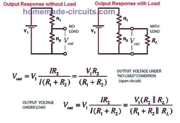
Though with AC, a resistive divider can also work, but the output may be affected by the load. A capacitive divider is frequency-dependent, and its output also depends on the load.
Voltage Divider Calculator
Enter any three known values and press "Calculate" to solve for the fourth.
How to Use this Potential Divider Calculator Tool
Using this voltage divider calculator is very simple. No need to do any hard calculations or use your brain. Just follow these easy steps:
- First of all, this calculator needs exactly 3 values to find the 4th value.
- Whichever value you want to calculate, just leave that box completely blank (empty). Don't type anything there!
- Fill up the remaining 3 boxes with your circuit details.
- For Resistors (R1 and R2), you can change the unit also. If your resistor is 1k ohm, select kilohms (kΩ) from the dropdown. If it is simple 220 ohm, select ohms (Ω).
- Now, just click on the blue Calculate button.
- Boom! The empty box will automatically fill up with the correct answer....
Practical Example
Example for quick understanding:
Suppose you have a 12V battery (Voltage Source = 12).
You want 5V output to run something, and you have a 1k ohm resistor for R1.
You don't know what value of R2 to use.
Now you just have to put VS = 12, R1 = 1 (select kilohms), VOUT = 5, and leave R2 box totally empty.
Click Calculate, and it will give you the exact value for R2 instantly!
If you make any mistake or leave two boxes blank, it will show a red error message. Just fix it and try again.
Questions & Answers
Can you please make a capacitive voltage divider calculator with acceptable-current concern consideration? (I would like to step down from 120VAC to 110VAC to power my soldering gun and more capacitive dividers for powering AC-to-DC wall warts needing 110VAC as well, but don’t know which capacitors to use. I would think to use MKP/polypropylene capacitors, but am not sure of the details, and don’t want to trip the breaker, set a fire, deliver improper voltage, or cause other problems.)
Hi, you can try the following calculators, but these won’t solve your high current load requirements, for your requirement you will need transformer or SMPS based power supplies.
https://www.homemade-circuits.com/capacitive-dropper-calculator-tool-for-transformerless-power-supplies/
https://www.homemade-circuits.com/capacitive-voltage-divider-calculator/
Thanks for the divider calculator.
My soldering iron is only 80W & thermostatic, MKP capacitors have alot of capacitance & not much ESR, but, if not, how about polymer capacitors or a combination of the 2 types?
I am trying to step down from 120V, and just under 110V is ideal (no need to always draw exactly 80W), but I don’t want to trip the 15A breaker (It has other loads too.) or cause capacitor ignition. I need AC output.
Sure, in that case you can apply the following concept, by adding just a single capacitor in series with your soldering iron input supply. The capacitor could be around 10uF/400V non polar PPC, or 10nos of 1uF/400V PPC in parallel.
https://www.homemade-circuits.com/capacitive-dropper-calculator-tool-for-transformerless-power-supplies/
I need AC output for my soldering gun.
Thanks.
You just need to connect a capacitor in series with your soldering iron supply input, and nothing else.
The capacitor can be a 10uF/400V PPC as suggested earlier, it will give your soldering iron an AC voltage with a restricted 500mA current, which will drop the 220V AC to the desired 120V AC automatically.
I don’t see how a single capacitor or capacitor divider can reduce such disparate voltages to the 110V the 80W or less the soldering iron element needs. AC input at 220V AC would clearly produce more voltage for the soldering iron and more current through its element than 120V AC.
The wall warts would be in even worse need of a 2nd capacitor.
I have suggested the single capacitor dropper specifically for your soldering iron current limiting, not for any other application. Please use and confirm the following calculator to calculate the max current:
https://www.homemade-circuits.com/capacitive-dropper-calculator-tool-for-transformerless-power-supplies/
The element is inside of the housing, & I’m concerned I might break it or be unable to fit all of that circuitry into it. Can you calculate for the capacitive divider to input 120V AC and only 80W to the 110V 80W element?
You will just need a single 200V series PPC capacitor for your requirement, which you can calculate using this software:
https://www.homemade-circuits.com/capacitive-dropper-calculator-tool-for-transformerless-power-supplies/
I have 120V AC, not 220V AC.
No problem, still you can use the 10uF capacitor as suggested in the previous comment…
Is there a way to wire the circuit constant-current without knowing Vout?
Vout is your target voltage, without knowing that, the calculation would not make sense….For your previous op amp based LED current regulator, the Vout will be 0.1V.
I don’t know what to enter to find resistances, or what range of nichrome or trimmer(s) to use to get the 300mA or 700mA to the LEDs. How much resistance can the op-amp deal with?
Let’s assume Vs is 5V, Vout is 0.1, take R1 as 1k, then R2 becomes 20 ohms. op amps can deal with any practical magnitude of resistors.