In the following post I have explained a simple circuit which can be used for alternately switching LEDs with gradual brightening and fading effects.
Circuit Operation
The circuit can be effectively used for generating spooky effects in idols, for example it can be used for illuminating the eyes of a Jack-o'-lantern during haloween celebrations.
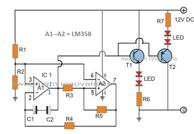
The circuit is overly simple and requires just a couple of op amps and a few other passive components for implementing the proposed brightening and fading actions in the LEDs.
The opamps can be a couple of separate IC 741 or a single IC with dual opamp such as IC 1458, 4558 or a TL072.
The opamp A1 is used for generating a gradual rising and sinking voltage, which ranges from 3 to 6 volts.
The opamp A2 is simply configured as a comparator for supplying an alternately varying voltage between 2 and 7 volts in order to charge and discharge C1 and C2 through a constant current input.
Thus the above operations become responsible for generating a linear peak to peak ramping signal at pin#1 of A1.
This signal is amplified with a couple of transistors wired as emitter followers to pin#2 of A1. Here the LEDs become the emitter loads of the transistors.
R4, together with C1 and C2 determines the rise and fall frequency of the connected LEDs.
R4 can be replaced with a 100K pot for making the fading rate manually adjustable.
The circuit should be operated from a 12V DC power supply for supporting at two LEDs on each channel.
For accommodating more LeDs, the collector of T1 and the upper end of R7 should be connected to a separate high voltage supply may be to a 30V supply which would then allow the connection of 6 LEDs on each channel.
Parts List for alternate brightening and fading LED circuit
- R1, R2, R3 = 56K,
- R4, R5 = 120K,
- R6, R7 = 150 OHMS
- C1, C2 = 33uF/25V
- T1 = BC547,
- T2 = BC557
- LEDS = 5mm, 20mA,


Questions & Answers
Hi,
I am looking to build a backlit sign for a small home recording studio, and want the lights to both come on and go off softly. This would say something like “Recording” or “Quiet” Ideally, the on-off intervals should be between 1 to 2 seconds, and should not be too bright so as to draw excess attention to the sign and not be too fast or abrupt. This circuit seems like it might work well in my application. I am unsure how many lights (LEDS) would be needed yet, but the sign would not likely be more than 14 inches long, and perhaps 8 inches high. Would this be a good circuit for this purpose? Thank you.
Hi, sure, the above circuit will do the job for you.
You can probably use a 24V supply and accommodate around 8 LEDs in series across the transistor emitters.
However, the two transistors would generate alternate illuminating patterns on the LEDs, meaning while one LED string is slowly shutting off the other LED string illumination would be slowly rising.
If you need only a fade ON/OFF feature then you can use just one transistor stage, the NPN one. Please let me know if you have any further doubts.
Thank you very much for your rapid reply, I appreciate it!
You are welcome!
Hi Swagatam,
What modifications would you suggest to this circuit to activate it with a PIR?
Hi Norman,
you can simply add the following PIR circuit for switching the power supply ON/OFF to the circuit:
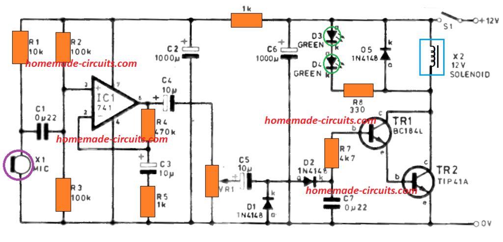
I have a common LED white light strip that I want to put inside my drums. I have built a trigger that will shoot power to the lights when I strike the drum head. All is good except I would like the lights to be instant on and 1 second fade out. Is that something you can help me with? Can I purchase this from you or can I purchase the components from you and you tell me how to assemble. I would need 6 of these. I have been calling, texting and emailing many to no avail. Hope you can help.
Do you a have transistor for driving the LED in your trigger circuit? This transistor base will need to be modified for the fading effect!
I noticed that you have NPN and PNP transistors controlling the LEDs. Is there any negative effect on the circuit if I use 2 NPN transistors configuring them as emitter followers?
Two NPN transistors cannot be used to work alternately in this design
I am a model railroader and a novice to building electronic circuts from scratch. I do use a volt meter and do understand how to read resistors, capacitors, etc., so I have some electronics knowledge (enough to be dangerous?).
I was looking for a circuit that alternately flash and fade LEDs (similar to a railroad crossing signal but with a fade effect). I found this LED Slow rise – Slow fall circut; which looked like it was exactly what I needed. I was able to successfully build and test the circuit and it works great.
But I have a question regarding the circuit’s operation. I was looking for a circuit that had a more pronounced fade to it; where the LEDs would fade to almost completely off.
My question is….what circuit change would I need to make to have that happen? BTW…..the frequency of the fading back and forth seems perfect.
I am glad you could built the circuit successfully despite of being a relatively newbie in the field.
To get a complete shut off at the end of the fading, you can try adding a 1N4148 diode in series with the LEDs, and see how it performs, you can even try a couple of diodes to make the shut off even more darker. The polarity of the diodes will be same as the LED polarity.
Hi Swagatam……WOW! Thanks for the quick response….you’re awesome! Funny story….I was swapping out various components to get the fade more pronounced and when I connected power on the last change I heard a POP and experienced the smell of dead electronics! Crap!
I took it all apart, replaced the IC, transistors and capacitors, tested the resistors and rebuilt the whole thing. And…..low and behold…..the fade effect was exactly what I was looking for! Whaaaa??
I reviewed a printout of the circuit I followed and discovery I missed connecting Pin 4 on the IC to ground on my first build! So I guess the “smoke test” was a blessing in disguise.
But I will make the changes you suggested to see what happens. This is SO mich fun!
Electronics is indeed a lot of fun, Glad you are enjoying it Steve, and hope my suggestions works to accomplish the pronounced fading effect!
Hi Swagatam, just wanted to touch base with you about this circuit I built. I troubleshot the circuit and found a bad transistor; which I probably damaged due to my novice soldering skills. lol
The circuit you helped me modify for the 12V ‘Superflux’ leds works great. I used it to power the eyes, heart and mouth of the Dragon I carved for the small boat I built. I entered my boat into the ‘Off Center Harbor’s’ “Worldwide Classic Boat Show” and it was accepted!
I included two pictures of my Dragon with the LEDs powered up for my boat’s description. If you’d like to see my entry, please go to the boat show ‘Entry’ page:
https://classicboatshow.com/listing/whispr-16-redmond-whisp-skiff-2019/
The ‘virtual show’ begins 2/19/21 at 2:00pm Eastern time.
Thanks again for your help on this circuit. It does just what I wanted and makes the Dragon look very cool!
Regards,
Rich
That’s amazing Rich, I am glad you could make it successfully, however, the link that you have attached seems to have expired, and there are no images in it. Would be great if you could resend them!
Hello Swagatam, I am once again bothering you about this circuit….
Ordered the parts from Digikey, including the 2n2222 (T1) and 2n2907 (T2) as you suggested to support use of the quad-LEDs (Superflux) each drawing 80 mA. I built the circuit on a 1/4 size breadboard, hooked my 12 Vdc power supply to it and, Voila, it worked! Hooray!
I inserted a 100Kohm trimmer pot in place of R4 to adjust the fade duration and I was amazed that I didn’t screw it up the first time through.
So, I then carefully built the circuit on a thru-hole prototype board, checked and re-checked my diagram, examined the board with a magnifying glass looking for newbie (which I am in spades) mistakes like solder bridges, cold joints or mis-wired connections. Everything looked good, so I applied 12V. No smoke, no sparks, no obvious failures, but here’s all that happens:
-Power on
-White LED (T2) briefly lights, goes out, no fade; just on, then off.
-Blue LED (T1) then lights at what appears to be full brightness and stays on.
-No rise/fall of brightness, no subsequent alternation.
-Power off.
Help in troubleshooting please!
I’ve popped the LM358 out of its DIP socket, replaced it with a spare; no change in operation.
Used my VOM to check continuity as I rechecked my circuit diagram.
Replace the PNP transistor because I ‘thought’ -11Vbe showed it to be a shorted device. No change in operation.
Re-cleaned board with Isopropol Alcohol and a soft brush.
Used magnifying glass and dental pick to make sure there was no path between through hole groups.
Re-drew the circuit using the prototype board circuit as a guide and compared to original diagram; both identical.
The circuit worked on the bread board beautifully, didn’t work once I soldered it to the prototype board; so, I must have messed up somehow! I’m at a loss as what to try next. Any suggestion(s) would be much appreciated.
Sorry for my long-winded message, but I thought I should be thorough.
Regards,
Rich
Thank you Rich for the detailed explanation, and glad you could breadboard it successfully. However it seems difficult to judge the fault in this case especially because the stripboard soldering is supposed to be more reliable than a breadborad assembly.
Did you recheck the op amp orientation? sometimes the solder side view can be confusing and assembler can end up numbering the IC pins in the reverse direction.
Hello, I hope you can help me adjust component values to allow the use of two (one for each leg) Oznium ‘Prewired Superflux 4 chip LEDs’.
Your circuit design is functionally exactly what I’m looking for, but being a ‘digitally-challenged-newbie’, I am at a loss as to what component/values need to be changed.
The Superflux LEDs are designed to work at 12v and each unit draws 80 mA.
Thanks in advance.
Rich
I guess those are same as the PIRHANA LEDs, and you can very easily use the above circuit simply by replacing the NPN transistor with a 2N2222 and the PNP with a 2N2907
Swagatam, thank you very much for the prompt reply to my question! I will go about sourcing the parts list components to breadboard this circuit. Looking forward to success at this new hobby. Your help in this project is really encouraging!
Regards,
Rich
No Problem Rich, wish you all the best with the project!
Hi Swagatam,
Adding the 4148 diodes in series with the red LEDs works. I actually added three 4148 diodes in series with the red LEDs and the timing for the red and blue LEDs is almost identical. Thanks so much for your help!
Sounds great Norman, I am glad it worked for you!
Hi Swagatam,
The circuit works great with both sets of LEDs being the same color. I would like one set red and one set blue. When I breadboard with one set red and the other set blue, the red does not stay off as long as the blue. What can I change in the circuit to get the red and blue to mimic each other as far as time on and time off?
Thanks Norman, It could be due to higher minimum forward voltage of blue LEDs than the red ones. Reducing blue led fwd voltage may not be possible, so may be you can try increasing the red LEDs fwd voltage by adding a 1N4148 diode in series with the red string. After this you can increase the C1, C2 values to 47uF and check the response.
LED Fader Circuit – Slow Rise, Slow Fall LED Effect Generator
Dear Mr. Swagatam,
As a Designer and artist completely untouched by the miracles of electrotechnical engineering, I seek your advice as it seems to me that you are a master of your trade.
Iam looking for a simple and foremost small little electronical module that can fade one (or more) white LEDs veeery slowly up and down in an interval of around 30 seconds or more. It must run on 12V DC. And no programming required. A simple hardware solution that lasts. Assembled it should not be bigger than 4×4 cm in width/depth and 3 cms in heigth. Its is planed to add a very subtle glowing effect to a small lamp I am building .
some of your described circuits seem to be quite close to my requirements.
However, as my lack of skill doesnt allow me to make the right adjutments to your circuits by myself, I may kindly asked you to help me with an adapted diagram and a partslist that will fit my needs?
Im a good craftsman, soldering and assembly shouldn´t impose any big problems on me.
I voluntarily can compensate you for your efforts.
With best regards
Jan Wachter
Thanks Jan, you can probably try the following two designs:
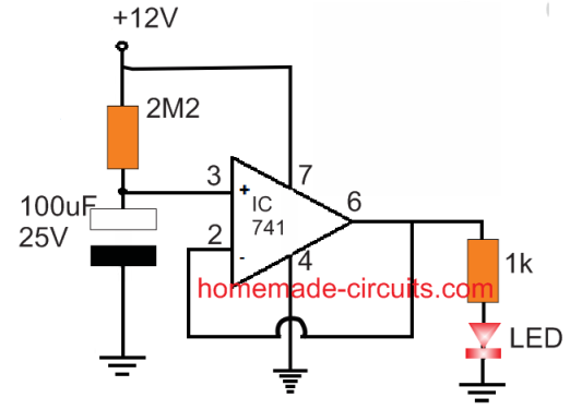
the second design can be simplified by eliminating the BC547 stage and replacing it with TIP122/LED section
The resistors are 1/4 watt 5%, LED is 20 mA, 5 mm type
Hey,
I want to design the soft start and soft stop circuit to drive 12 volts solenoid valves. I have a switch connected to turn on/off. Can you please help in designing a ramp circuit.
Hey, you can try implementing an transistor emitter follower with a capacitor across base/emitter, and the solenoid load across emitter ground. The details of an example circuit are as follows:
TIP122 transistor, with base connected to positive via 1 k.
100uF/25V capacitor connected across base/ground.
Load connect across emitter/ground
collector connected directly to positive
Here ground refers to the negative line from the supply
Thank you so much for your help. I have simulated the circuit it works fine during the soft start but soft stop is too fast. when i try to change the capacitance to achieve the required ramp at soft stop the time of soft start increases more than desired amount. Any solution for this?
Your help is much much appreciated.
No problem, you can try putting the capacitor between two resistors, meaning put two series resistors 1k + 1k or other values, and put the capacitor between the junction of these two resistors, and ground.
First, thank you. I appreciate the time and effort afforded to this website and the wealth of knowledge within.
Unfortunately, I see a problem in this schematic. Vcc+ connects pin 8 on the 4558 and 1458; and to pin 7 on the 741 and TL078. Pin 4 is Vcc- on all 4 chips. So, what you labeled as pin 4 should be pin 8; and what you labeled as pin 11 should be pin 4. It is also a little confusing to see 2 op amps symbols (which are both 8 pin chips), but they appear to be labeled to match an 8 pin dual op amp.
I hope this info helps future readers. Again, thanks for your time … and the circuits.
Thank you for notifying the correction, I have updated the new diagram accordingly.
i am using an led light strip.. the circuit is correctly connected but the fading effect is not shown.. what should i do now?
how can you say you did everything correctly when you have not connected the pin4/7 to the supply rails?
obviously you must connect them to the supply, otherwise how will the IC work…?
yes i have used all connections correctly also i have tested the circuit for single led but the result is the same… should i connect the +ve terminal of power supply to pin #7 and negative to pin #4?
did you connect the 741 pinouts correctly? use a single LED or 2 LEDs as shown in the diagram to test the effect, don't use strip.
have i used the correct opamps?? there is no #9 and #11 pin on opamp A1
the diagram shows a dual opamp IC, that means two opams in one package.
but in the circuit given there is no connection of power directly to the IC through pin #t and #4
for IC 741, pin#7 is the positive supply, and pin#4 is the negative supply pins.
pin#3 is the (+) input pin
Pin#2 is the (-) input pin,
pin#6 is the output.
you must modify the connections according to this
What is A1 and A2?? I made the whole circuit,connected everything but it's not working.. i used IC 741 as A1 and A2
A1 and A2 are opamps, please check all the connections once again and also the polarity of the capacitors…you can also try reducing the voltage to test the response
Good morning sir,
THANK YOU VERY MUCH…. 🙂 🙂 🙂
K.Kausik
Sir,
I'm really sorry. Apologizing for any kind of mistake.
I didn't maintain the name with any kind of intention.
Actually I always try to gather information before asking you anything,just to provide you more free time,that you may help others, all over the world. Not only me but the visitors out of India also appreciate your attitude to help and responsibility to answer as soon as possible. And that adds some extra colour in your website and it's the only green tree in the desert.
I really feel proud to you and like to pray for your prosperity and happiness.
Again I'm really sorry for any kind of mistake.
Thanking you,
K.Kausik
Kaushik, please do not apologize, I know that you innocently included the external link without knowing that such links were not acceptable in most websites….
You are one of the avid and dedicated readers of this blog and I appreciate and value your involvement very much.
So please keep up the good work and feel free to comment whenever you have a query or doubt regarding anything in electronics.