Biasing the terminals of a bipolar transistor using a calculated resistive divider network for ensuring an optimal performance and switching response is called voltage divider biasing.
In the previous bias designs that I will explained the bias current ICQ and voltage VCEQ were a function of the current gain (β) of the BJT.
But, as we know that β can be vulnerable to temperature changes, particularly for silicon transistors, and also the true value of beta is often not properly identified, it could be advisable to develop a voltage-Divider bias in BJT circuit that may be less prone to temperatures, or, simply independent of BJT beta itself.

The voltage-divider bias arrangement of Fig. 4.25 can be considered one of these designs.
When examined with an exact basis the susceptibility to variations in beta looks really modest. If the circuit variables are appropriately worked out, the levels of ICQ and VCEQ could be virtually completely independent of beta.
Remember from earlier explanations that a Q-point is characterized with a fixed level of ICQ and VCEQ as demonstrated in Fig. 4.26.
The degree of IBQ can change depending on the variations in the beta, but the operating point around the characteristics identified by ICQ and VCEQ can easily remain unchanged if appropriate circuit guidelines are applied.
As mentioned above, you will find a couple of approaches which can be employed to investigate the voltage divider setup.
The reason behind the selection of specific names for this circuit will become evident during our analysis, and will be discussed in the future posts.
The very first one is the exact technique which can be carried out on any voltage-divider setup.
The second one is called the approximate method, and its implementation becomes feasible when certain factors are fulfilled. The approximate approach enables a far more direct analysis with minimum effort and time.
Additionally this can be very much useful for the "design mode" which we'll talk about in the later sections.
On the whole, since the "approximate approach" could be worked with most of the conditions and thus must be evaluated with the same level of attention as the "exact method".
Exact Analysis
I will explain how the method of exact analysis can be implemented with the following explanation
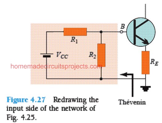
Referring to the following figure, the input side of the network could be reproduced as depicted in Fig. 4.27 for the dc analysis.
The Thévenin equivalent network for the design on the left side of the BJT base B then can be determined in a way as illustrated below:

RTh: The input supply points are replaced by an equivalent short-circuit as shown in Fig. 4.28 below.


ETh: The supply voltage source VCC is applied back to the circuit, and the open-circuit Thévenin voltage as appearing in the Fig. 4.29 below is evaluated as given below:
Implementing the voltage-divider rule we arrive at the following equation:


Next, by recreating the Thévenin design as illustrated in Fig.4.30, we evaluate IBQ by first applying Kirchhoff’s voltage law in the clockwise direction for the loop:
ETh - IBRTh - VBE - IERE = 0
As we know IE = (β + 1)IB Substituting it in the above loop and solving for IB gives:

Equation. 4.30

At first glance you may feel Eq. (4.30) looks quite different from the other equations which are developed so far, however a closer look will show that the numerator is just a difference of two volt levels, while the denominator is the result of base resistance + emitter resistor, which is reflected by (β + 1) and is no doubt very similar to Eq. (4.17) (Base Emitter Loop)
Once IB is calculated through the above equation, the rest of the magnitudes in the design could be identified through the same method as we did for the emitter-bias network, as shown below:

Equation (4.31)

Solving a Practical Example (4.7)
Calculate the DC bias voltage VCE and the current IC in the below shown voltage-divider network Fig. 4.31
Figure 4.31 Beta-stabilized circuit for Example 4.7.

Approximate Analysis
In the above section I will explained the "exact method", here we'll discuss the "approximate method" of analyzing the voltage divider of a BJT circuit.
We can draw the input stage of a BJT based voltage-divider network as shown in the figure 4.32 below.
The resistance Ri may be considered as the resistance equivalent between base and ground line of the circuit, and RE as the resistor between emitter and ground.
From our previous discussions [Eq. (4.18)] we know that the resistance reproduced or reflected between base/emitter of the BJT is expounded by the equation Ri = (β + 1)RE.
If we consider a situation where Ri is considerably bigger than the resistance R2, will result in IB relatively smaller than I2 (remember current always tries to find and move to the direction of minimum resistance), and thus I2 will turn approximately equal to I1.
Considering the approximate value of IB to be essentially zero in relation to I1 or I2, then I1 = I2, and R1, and R2 could be regarded as series elements.

Figure 4.32 Partial-bias circuit for calculating the approximate base voltage VB.
The voltage across R2, which originally would be the base voltage could be evaluated as shown below, by applying the voltage-divider rule network:

Now since Ri = (β + 1)RE ≅ βRE, the condition that confirms whether the execution of the approximate method is feasible or not is decided by the equation:

Simply put, if the value RE times the value of β, is not less than 10 times the value of R2, then it may be allowed to implement the approximate analysis with optimum precision
After VB is evaluated, the VE magnitude could be determined by the equation:

while the emitter current could be calculated by applying the formula:

The voltage from collector to emitter can be identified by using the following formula:
VCE = VCC - ICRC - IERE
However since IE ≅ IC, we arrive at the following equation:

It should be noted that in the series of calculations that we made from Eq. (4.33) through Eq. (4.37),,the element β has no presence anywhere, and IB hasn't been calculated.
This implies that the Q-point (as established by ICQ and VCEQ) as a result is not dependent on the value of β
Practical Example (4.8):
Let's apply the analysis on our earlier Figure 4.31, using approximate approach, and compare solutions for ICQ and VCEQ.

Here we observe that the level of VB is identical to that of ETh, as evaluated in our previous example 4.7. What that means basically is, the difference between the approximate analysis and exact analysis is influenced by RTh, which is responsible for separating ETh and VB in the exact analysis.
Moving ahead,

Next Example 4.9
Let's carry out the exact analysis of Example 4.7 if β is decreased to 70, and find out the difference between the solutions for ICQ and VCEQ.

Solution
This example may not be taken as a comparison between exact versus approximate strategies rather only for testing the degree at which Q-point may move in case the magnitude of β is reduced by 50%. RTh and ETh are given as the same:
Arranging the results in a tabular form gives us the following:

From the above table we can distinctly figure out that the circuit is relatively unresponsive to the change in β levels. Despite the fact that β magnitude has been significantly reduced by 50%, from the value of 140 to 70, although the values of ICQ and VCEQ are basically the same.
Next Example 4.10
Evaluate the levels of ICQ and VCEQ for the voltage-divider network as shown in the Fig. 4.33 by applying the exact and approximate approaches and compare the resulting solutions.

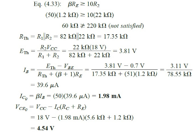
In the present scenario, the conditions given in Eq. (4.33) may not be satisfied, however the answers may help us to identify the difference in the solution with the conditions of Eq. (4.33) not being taken into account.
Figure 4.33 Voltage-divider network for Example 4.10.

Solving using Exact Analysis:

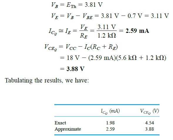
Solving using Approximate Analysis:
From the above evaluations we are able to see the difference between the results achieved from exact and the approximate methods.
The results reveal that ICQ is around 30% higher for the approximate method, while VCEQ is 10% lower. Although the results are not quite identical, considering the fact that βRE is just 3 times greater than R2, the results are actually not too wide apart either.
Said that, for our future analysis we will be predominantly relying on the Eq. (4.33) to ensure maximum similarity between the two analysis.
Hi Mr Swagatam;
I want to make a voltmeter which will measure both AC and DC. I mean circuit current is not issue for me. Please suggest which one is better / safer for me as a divider with resistances or capacitors or bjt divider? Thanks a lot.
Hi Suat,
if current is not an issue for you then I guess using a simple resistive divider would be the best option.
Hi Swagatam; Ref. to example 4.10, please help me on the followings;
— input voltage is dc or ac or both of them may be?
— as far as i understand, 18 volts at the top should be the main voltage of the circuit but i am not able to understand that the voltage symbol at the left side to the base before the capacitor so from where it comes.
— i think that the capacitor should be polarized and dark black colored box represents the (+) pole?
Best wishes
Hi Suat,
Referring to the following diagram:
https://1.bp.blogspot.com/-8-asI88X1ps/XAiXvZt69II/AAAAAAAAYMQ/G-7MOmQ9rqUqYX53v8QpD8G2fROWM-fmwCLcBGAs/s1600/1.jpg
Input voltage signal should be AC, DC will not work.
Yes 18 V is the main supply voltage to the circuit, but I cannot see any voltage symbol at the left side to the base before the capacitor?
The capacitors can be polarized or non-polar it does not matter.
Hi Swagatam;
The above subject is complex for me. For instant it is possible to decrase 24 Volts to lower voltage (ie. 24 V to 10 V) by using the such kind of loop in the circuit or the subject is related to current status?
Best Wishes
Hi Suat,
Yes decreasing the output voltage using voltage divider and a BJT is possible without affecting the current.
So are you saying that Ic = beta * Ib does not apply for the voltage divider bias and instead Ic is determined by Ie which in turn is set by Re. This is what I understand and I came across this webpage while searching for an answer to this question I posted on stack exchange.
https://electronics.stackexchange.com/questions/465386/fixing-the-collector-current-for-a-bjt-amplifier
Yes it must be correct, actually I have written exactly what I learned from the book “electronic devices and theory” by ROBERT BOYLESTAD LOUIS NASHELSKY
Hi
I have a weird circuit request… not sure if you can help. I’m looking for a headphone amp for an electric guitar that also has a passthrough connector, so the signal from the guitar can be amplified for earphones but also passed through to an amp/mixer
Hi, there are a few circuits in the following post which you can easily customize for your specific need:
https://www.homemade-circuits.com/4-channel-dj-audio-mixer-circuit-part-1/
The headphone amplifier can e used for the headphone, and its inputs can be also used for feeding another power amp