In this post I will explain a few circuit diagrams for building AC motor speed controller circuits using back EMF concept.
Working Principle of AC Motors
All household appliances like electric drills, sanders, sewing machines, and food mixers utilize AC electric motors of the series-wound type.
While in operation, these motors generate a back-electromotive force (back-emf) that is directly proportional to their speed.
The effective voltage applied to these motors equals the actual supplied voltage minus the back-emf.
This intriguing fact inherently endows these motors with a self-regulating capability regarding their speed.
An increase in the motor's workload naturally leads to a reduction in speed and back-emf, consequently boosting the effective applied voltage and ultimately causing the motor's speed to revert to its initial value.
Using Triac
Most AC motors are typically engineered to offer single-speed functionality. To impart variable speed control to these motors, one can readily employ Triac phase-controlled circuits.
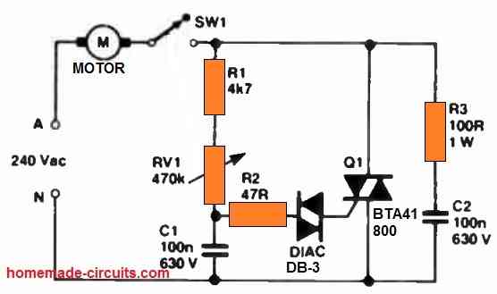
An example of such a circuit is illustrated in the following figure. This particular circuit proves especially advantageous for managing lightly loaded appliances like food mixers and sewing machines.

Nonetheless, it's important to note that the range of control provided by this setup is somewhat limited.
In contrast, electric drills and sanders contend with substantial fluctuations in load, rendering them less compatible with the above AC motor speed controller circuit.
Using SCR
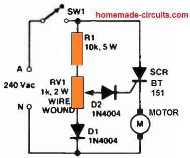
For these high-load appliances, the preferable choice is the AC variable speed regulator circuit depicted in the following figure.

In this configuration, an SCR serves as the control element, delivering half-wave power to the motor (resulting in a reduction of around 20% in available speed/power).
During the off half-cycles, the SCR senses the motor's back-emf, thereby facilitating automatic adjustment of the subsequent gating pulse, which aids in achieving some degree of speed regulation.
The network composed of R1, RV1, and D1 allows for a phase adjustment of 90 degrees, ensuring that all motor power pulses maintain a minimum duration of 90 degrees and deliver substantial torque.
At lower speeds, the circuit enters a 'skip cycling' mode, where power pulses are intermittently supplied to suit the motor's load conditions.
Delivering High Torque
This type of AC motor speed controller circuit excels in delivering substantial torque at low speeds but may exhibit some motor 'chattering.'
Similar to the prior circuit, it's essential to recognize that it offers only a limited range of control.
Closed Loop AC Motor Speed Controller using Back EMF
The next article presented below explains a very simple closed loop AC motor speed controller circuit that may be used for controlling single phase AC motor speeds.
The circuit is very cheap and uses ordinary electronic components for the required implementations.
The main feature of the circuit is that it’s a closed loop type, that means the speed or the torque of the motor can never get affected by the load or the speed of the motor in this circuit, on the contrary the torque is indirectly proportional to the magnitude of the speed.
Circuit Operation:
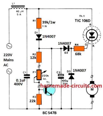
Referring the circuit diagram of the proposed single phase closed loop AC motor controller, the involved operations may be understood through the following points:
For the positive half cycles of the input AC, the capacitor C2 is charged through the resistor R1 and the diode D1.

The charging of C2 persists until the voltage across this capacitor becomes equivalent to the simulating zener voltage of the configuration.
The circuit wired around transistor T1 effectively simulates the operation of a zener diode.
The inclusion of the pot P1 makes it possible to adjust the voltage of this “zener diode”. Precisely speaking, the voltage developed across T1 is literally determined by the ratio between resistors R3 and R2 + P1.
The voltage across the resistor R4 is always maintained equal to the 0.6 volts that’s equal to the required conducting voltage of T1’s base emitter voltage.
Therefore it means that the above explained zener voltage should be equal to the value that may be acquired by solving the expression:
(P1 + R2 + R3 / R3) × 0.6
Parts List for the above closed loop AC motor speed controller circuit
- R1 = 39K,
- R2 = 12K,
- R3 = 22K,
- R4 = 68K,
- P1 = 220K,
- All diodes = 1N4007,
- C1 = 0.1/400V,
- C2 = 100uF/35V,
- T1 = BC547B,
- SCR = C106
- L1 = 30 turns of 25 SWG wire over a 3mm ferrite rod or 40 uH/5 watt
How the Load is Positioned for a Special Reason
A careful investigation reveals that the motor or the load is not introduced at the usual position; rather it’s wired up just after the SCR, at its cathode.
This causes an interesting feature to be introduced with this circuit.
The above special position of the motor within the circuit makes the firing time of the SCR dependant on the potential difference between the back EMF of the motor and the “zener voltage” of the circuit.
That simply means that the more the motor is loaded, the quicker the SCR fires.
The procedure quite simulate a closed loop type of functioning where the feedback s received in the form of back EMF generated by the motor itself.
However the circuit is associated with a slight drawback. The adoption of an SCR means the circuit can handle only 180 degrees of phase control and the motor cannot be controlled throughout the speed range but only for 50% of it.
Another disadvantage associated due to the inexpensive nature of the circuit is that the motor tends to produce hiccups at lower speeds, however as the speed is increased this issue completely disappears.
The Function of L1 and C1
L1 and C1 are included for checking the high frequency RFs generated due to the rapid phase chopping by the SCR.
Need less to say the device (SCR) must be mounted on a suitable heatsink for optimal results.
Back EMF Drill Speed Controller Circuit
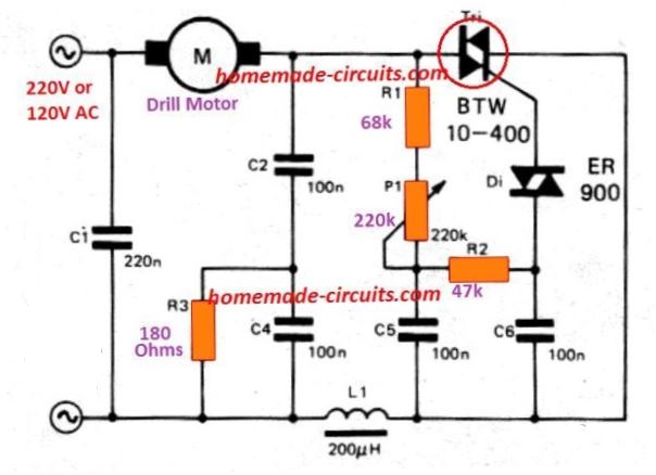
This circuit is mainly used to control the steady speed of smaller series wound motors, as found in several electric hand drills, etc.
The torque and the speed is controlled by P1 potentiometer. This potentiometer configuration specifies how minutely the triac could be triggered.

When the speed of the motor drops just under the preset value (with load connected), then the motor 's back EMF decreases.
As a result, voltage around through R1, P1, and C5 rises so that the triac is activated earlier and motor speed tends to increase. A certain proportion of speed stability is achieved in this manner.
What role does C6 play in the firing time of the TRIAC
It converts each single firing pulse for the diac/triac into small bursts of pulses.
thanks
Bonjour, que faudrait -il faire pour un controle du moteur en surintensité afin de couper le triacs fonction que l’on trouve dans les verins de portails? MERCI
Dear I
try to install vfd for motors of neither small workshop at home
1.5 kw motors approx, electric
saw etc I use diac and triac bt139 800, but my question is with the harmonics
The reason is that my workshop is at the back of my house and the start-ups are strong because of the house lines
I have two sets of diac / triac, and I cannot find filters for these applications, I
would put a resistor and capacitor in parallel to the load in each case.
What value do you recommend? Voltage
220 volts at 50 Hz
Norberto
Hello, you can add a RC snubber, across the triac, but I think a snubber across a triac is required for protecting the triac from high voltage spikes, it is mostly not for harmonics. For harmonics you can try adding a 1uF/400V capacitor right across the motor wires and see if that helps
Sir, how could I simulate this circuit? I mean what software should I use?
Ibrahim, I never use simulator for my circuits, so can’t help much with this subject
you can use use proteus
Avrei un problema da risolvere
e’ possibile avere un circuito di protezione da cortocircuito e limitatore di potenza
su un alimentatore variabile da 300V DC.
Grazie per il VS aiuto
Gabriele
Hello Friend! Does this project work on a 1.4 hp 90v engine?
Hello friend, it will work if the motor is a series wound motor…
The resistor values in the parts list don’t match the circuit diagram.
I have corrected the parts list now so that they match with the diagram.
The diagram says voltage controlled by “P1, R3 and R4” Should this not be P1, R3 and R2 as these are the inputs to the base of the transistor?
R4 is the current limiter for the the Triac.
You are right, thank you for pointing out the mistake, I have corrected it now in the article.
I used a triac based dimmer to control ac 220v fan speed but motor creates hum noise in low speed. Is there any other circuit to control speed without hum noise?
use inductor capacitor filter as shown in the last diagrams of this article:
https://www.homemade-circuits.com/how-to-make-simplest-triac-flasher/
Can this circuit be used with a capacitor start motor?
Yes it can be tried…
Hi
does this cirquit work with 220v or is designed for 110v thanks
Hi, it can be used for both 220V and 120V inputs
What maximum power of the motor it can control and what components should be used for the speed controller for motor 1000 – 1200 watt, 115 v,
upto 300 watts can be controlled with the shown set up, for higher wattage you may have to upgrade the SCR with a higher value, and also reduce the gate resistor value appropriately
Does it control motor speed precisely without a use of tachogenerator?
Do you have the inductance value of L1? May i use a toroidal inductor instead?
By the way, amazing blog you have, and i really appreciate that you answer!
L1/C1 are not crucial, they are placed for PFC….to reduce RF interference in the atmosphere.
still if you want to include them , you can try 200 turns of 24 SWG magnet wire on any iron core such as an iron bolt.
I am glad you liked my website…please keep reading.
Will this circuit provide a stable frequency of revolution (RPM) even under load?
Meaning the motor will keep spinning at the same speed even when a load is aplied?
yes it will as long as long as the input voltage does not fluctuate….
Thanks!
Im thinking to use it to control a washing machine universal motor in order to make a belt sander.
Will a 10amp thyristor be enought?
Also, what power dissipation capability will be needed in the resistors?
The design was originally intended to control drill machines, so probably any similar motor can be controlled with this circuit, although the capability is restricted to 180 degrees only….The resistors can be all 1/4 watt rated, a 10amp SCR will do if the motor max consumption does not exceed this value.
Sir , How AC supply to motor is completed? Means Both the half cycles. My another Q is can I connect Transfomer pri to control 230 ac v , so that sec volage automaticaly get controlled. Sir Expecting your reply. my email vijayraopathak@yahoo.co.in
Thanks, & Regards,
Pathak, the above circuit will control only one half cycles of the AC and therefore will be able to provide a 180 degree phase control only….for full control you can make any regular dimmer switch circuit….the transformer can be also controlled by using a dimmer switch circuit in by connecting it series with the trafo primary
at what voltage??
what kind of motor (HP or Wattage) can you aplly this circuit to?
you can use any wattage AC motor provided the SCr is rated appropriately for handling the current.
P1 = VR1
yes.
I would like to ask, What is this P1?
Where's P1?