The following circuit was taken from an old electronic book, it is indeed a very nice little two transistor radio receiver circuit which utilizes very few components yet is able to produce output over a loudspeaker and not just over headphones.
Circuit Operation
As can be seen in the given circuit diagram, the design is as simple as it can be, just a couple of general purpose transistors and a few other passive components for configuring what looks like a nice little AM radio receiver unit.
The circuit functioning is pretty basic. The antenna coil collects the MW signals present in the air.
The trimmer sets and tunes the frequency which needs to be passed across to the next stage.
The next stage which comprises T1 functions as a high frequency amplifier as well as a demodulator. T1 extracts the audio from the received signals and amplifies it to some extent so that it may be fed to the next stage.
The final stage employs the transistor T2 which operates as a simple audio amplifier, the demodulated signal is fed to the base of T2 for further amplification.
T2 effectively amplifies the signals so that it becomes audible over the connected speaker loud and clear.
T1's emitter has been configured as a feedback link to the input stage, this inclusion greatly enhances the performance of the radio making it extra efficient while identifying and amplifying the received signals.
Circuit Diagram
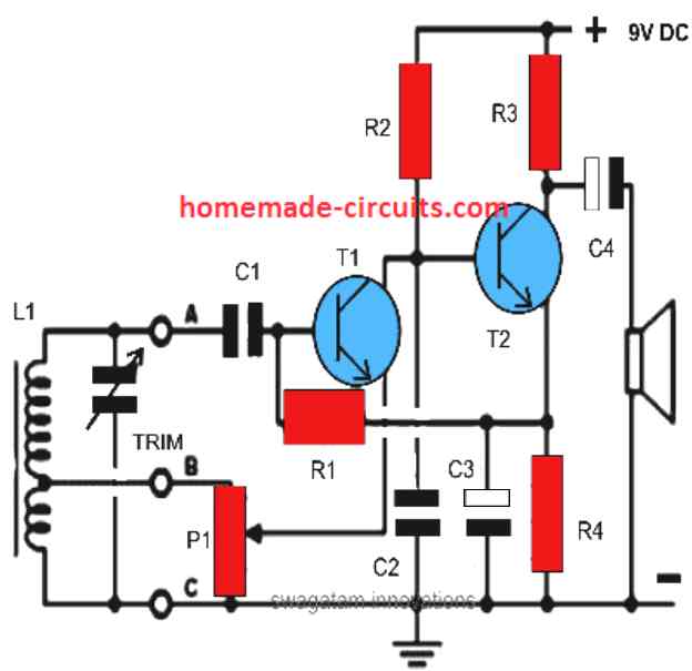
Parts List for a simple 2 transistor radio receiver with speaker
- R1 = 1M
- R2 = 22K
- R3 = 4K7
- R4 = 1K
- P1 = 4K7
- C1 = 104
- C2 = 470pF
- C3,C4 = 10uF/25V
- T1 = BC547
- T2 = 8050 or 2N2222
- L1 = ordinary MW antenna coil
- SPEAKER = small earphone 10k
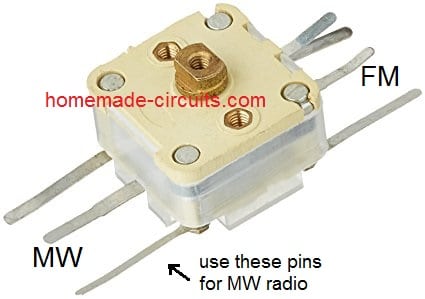
- TRIM = ordinary GANG
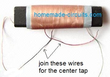
MW Antenna Coil on Ferrite Rod (L1)
Use the Following type of GANG Condenser for the Trimmer (use the center pin and any one of the output pins from the MW side)
Simple AM radio Circuit using FET
Despite having so few parts, the following little AM broadcast band receiver circuit operates astonishingly well.
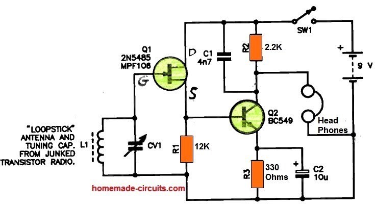
It is possible to remove the tuning coil [L1] and capacitor (CV11) from an obsolete transistor radio; L1 is the loopstick antenna.
In order to produce a sound across R2, a JFET, Q1, is utilized as a high impedance source-follower, directly connected with transistor Q2, which is employed here as an amplifier and collector-bend detector.
The transistor's collector characteristics provide the necessary rectification of the signal.
The rectified RF is bypassed by C1. C2, which is ideally of the tantalum type, bypasses the emitter bias resistor R3 of Q2 for optimal performance.
For excellent sound output levels, use high impedance headphones.
A 9 V transistor radio battery may be used to power the circuit.
Simple High Performance MW Receiver Circuit
An Improved version of the above Medium Wave radio can be studied in the following paragraphs. Once built it can be expected to work immediately without any hassles.
The MW receiver works with four transistors.
The first transistor is configured to work in the reflex mode. This helps just one transistor to do the job of two transistors which results in a much higher gain from the design.
The working efficiency may not be as good as a superhetrodyne, nevertheless is just enough for a good reception of all local stations.
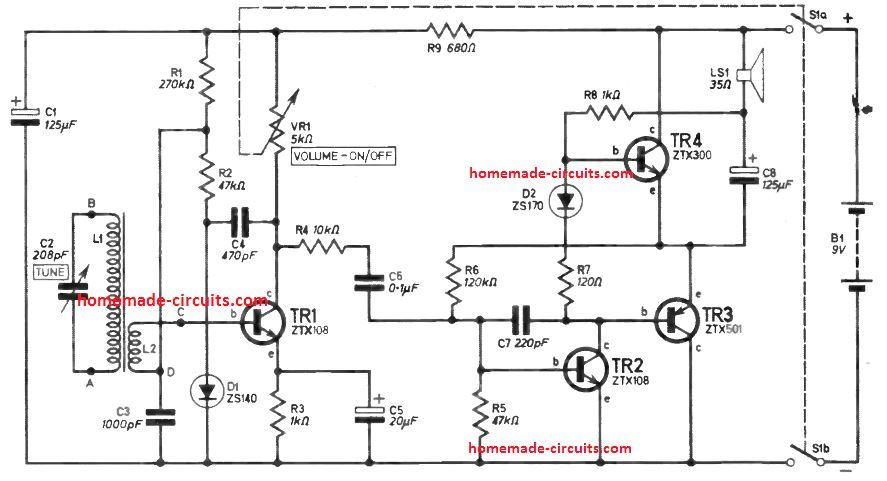
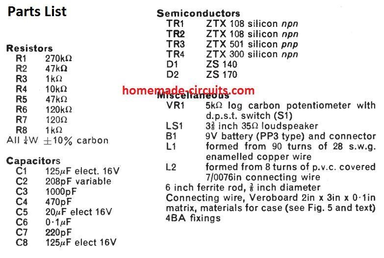
The transistors can be BC547 and BC557 for the NPN and the PNP respectively, while the diode can be 1N4148.
The Antenna Coil could be built using the following data:
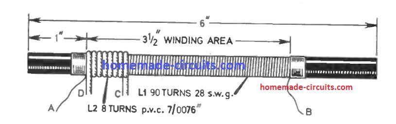
The ferrite rod antenna coil picks up the AM frequency through the tuned network of C2, L1. The tuned AM signal is fed to the first transistor TR1 via L2.
This enables a correct matching of the high impedance input from C2, L1 with the transistor input, without causing any deteorioration of the tuned signal.
The signal gets amplified by TR1 and is fed to the detector stage made using the diode DI.
Here since the 470pF capacitor C4 responds with a lower impedance to the incoming r.f. (radio frequency) than the 10 kilohm resistance R4, implies that the signal is now forced to enter through the capacitor C4.
This filters out the audio element in the signal after D1 detection, and is sent through the R2, L2 stage to the base of TR1.
C3 eliminates any form of stray RF.
Next is C4, which offers a high impedance to the signal compared to R4, which prompts the signal to move to TR2 base.
Audio Amplifier
Transistors TR2, TR3 and TR4 work like a push-pull amplifier.
TR3 and TR4 behave like a complimentary output pair while TR2 functions in the form of a driver stage.
The pure audio signal extracted from TR1 is amplified by TR2. The amplified positive cycles of the audio signal feed the TR4 through D2 while the negative cycles are sent through TR3.
The two signals are eventually combined back using C7 after the amplification process is completed. This finally produces the required output audio MW music over the loudspeaker LS1
The next MW or AM receiver is actually so easy that really tiny expenditure is necessary for its construction, and as just a few number of parts are employed it is ideally suits a mini radio receiver, that effortlessly accommodates inside a shirt pocket.
Even so it provides very good reception of nearby radio stations with no need for an external antenna or earth wire.
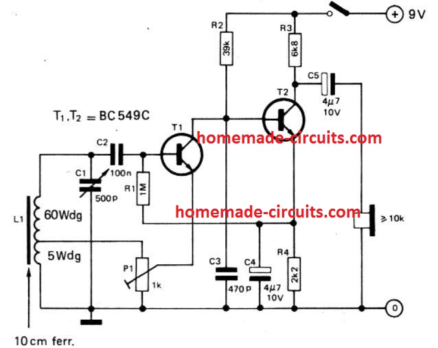
Functioning of the receiver is extremely straightforward. Transistor T1 works like an r.f. amplifier and detector with regenerative (positive) feedback. The level of feedback, and therefore the sensitivity of the MW receiver, could be manipulated by varying P1.
Even though output to the base of T1 is obtained straight from the upper section of the tuned circuit L1/C1, instead of through a coupling winding, the impedance offered by T1 is quite enough to make sure that the resonant circuit is barely suppressed.
Because the current gain of T1 decreases on the higher frequency side of the spectrum, while the input impedance rises, the gain of this stage continues to be relatively consistent on the entire spectrum, in order that it is normally not essential to fine-tune P1 often.
Signal detection happens on the collector of T1 and the output impedance of this T1 stage and C3, cleans out the r.f. portion of the rectified signal. T2 supplies further amplification of the a.f. Signal to operate the attached crystal earpiece.
PCB Layout and Construction Details
Construction An extremely stream-lined PCB layout is shown below for the proposed AM receiver. L1 must be positioned as near as is possible to the PCB surface to prevent oscillation issues.
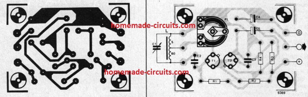
Individuals who want to miniaturize the layout even more may try things out by decreasing the measurements of the ferrite rod and adding more number of winding to obtain the very same inductance, while in case L1 is built smaller an external antenna could be required, which could be attached on the upper terminal of L1 through a 4.7 p capacitor.
The proposed dimensions for L1 will be 65 turns of 0.2 mm (36 S.W.G.) enameled copper wire over a 10 mm diameter 100 mm long ferrite rod, with the center tap coming out at 5 turns away from the `ground' end of the antenna coil.
C1 could be a small (strong dielectric) 500 pF gang condenser, or to get signals from a single fixed station only it might be substituted with a permanent capacitor of just lower than the necessary value in parallel with a 4 to 60 pF trimmer.
This may make it possible for the dimensions of the MW radio receiver to become additionally minimized.
Last but not least, the working current of the receiver is incredibly minimal that around 1 mA) in order that it will probably run for many months with a PP3 9 V battery.
Capturing Unwanted AM Radio Signals
The circuit displayed below is a tunable AM signal trap circuit which can be controlled to retrieve unwanted AM signals and channel the remainder to the receiver.
Inductor L1 is used as a broadcast loopstick-antenna coil whereas capacitor C1 is set for tuning. You can easily get these components from an old radio.
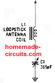
If the interfering signal comes from the lower frequency side of the broadcast band, you need to set L1’s slug around ¾ of the way into the coil and adjust C1 for a minimum signal output at the interfering frequency.
Once the interfering station’s frequency is close to the upper end of the band, regulate the slug until the end of the coil and tune C1 until you get a minimum signal.
It can happen that some unwanted transmitter signal besides a typical AM-broadcast type waves can get into the tank circuit.
When that happens, you must find out the transmitter’s frequency and choose a coil/capacitor arrangement that will resonate at that frequency. Then, connect that combination to the schematics above.
AM Signal Extractor
The following design is a frequency-selective circuit that be replaced for a LC tank discussed above.
When the expected signal can be detected but masked with noise, this circuit does the ‘unmasking’ tasks and delivers the signal to the receiver via the tank circuit.
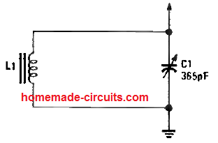
When the tuner is boosting the required level for the frequency, it is also suppressing all other signals outside its passband. You can easily use the same combination of values for the capacitor and coil as depicted above..
Other kinds of antennas and selective circuits can be evaluated through the input of this tank circuit.
A huge tuned loop will provide the circuit an option to help reduce an interfering signal arriving from diverse directions.
If there isn’t space for a big loop, you can opt for a large, tune ferrite coil as a replacement and hold its feature.
AM Booster Circuit
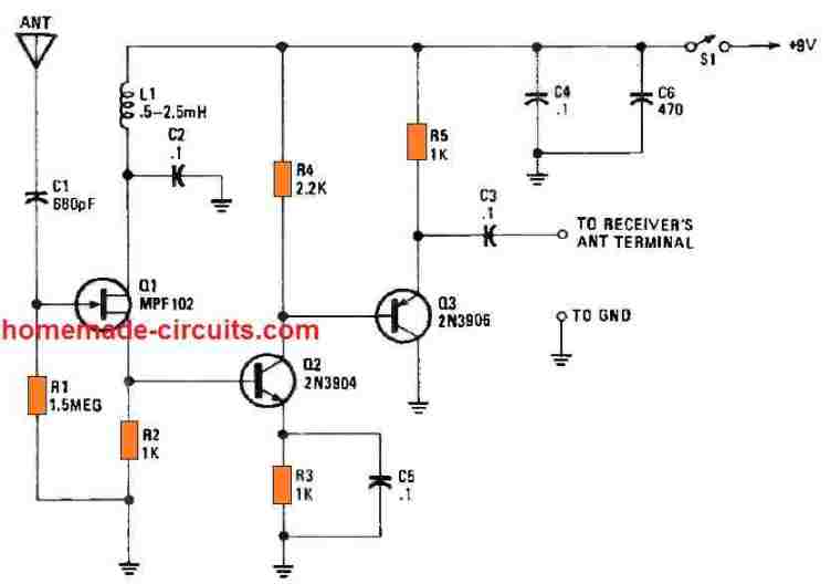
The above AM signal tuner circuits can be effectively attached with the signal booster circuit below for creating an enhanced antenna system for any AM radio.
You just have to connect the arrow head side of the above explained LC circuits with the gate of the FET Q1 in the below shown circuit.
Another Simple AM Radio Antenna Booster Circuit
The following AM booster circuit can significantly enhance poor AM broadcast reception if that is a problem for you.
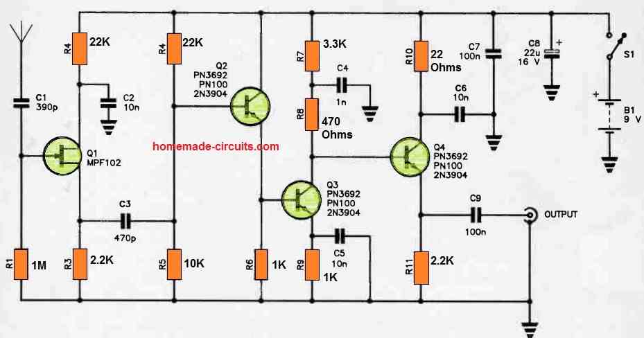
It is a four stage wideband amplifier with a high impedance input that may be used with a modestly sized vertical whip antenna.
The antenna is directly connected to the Q1 JFET in the first stage's gate.
This stage was built for a high input impedance because short whip antennas exhibit a high feedpoint impedance.
The AM radio signal at the source flows through C3 to the base of Q2, which functions like a common-collector stage.
Q1 is configured like a common-drain stage. Effective input-output isolation is provided by this configuration.
In the next stage, Q3, which functions as a common-emitter amplifier, is directly connected to Q2's emitter.
Its collector is directly linked to the common-collector emitter follower amplifier Q4's base. The signal is capacitively linked through stage C9 to deliver an impedance-low output.
Due to the splitting of load resistance and Q4's bypassing of the split load resistance, only a portion of Q2's collector load is active at RF.
Due of the circuit's minimal electricity consumption, a transistor radio battery is used to power it.
TRF MW Receiver
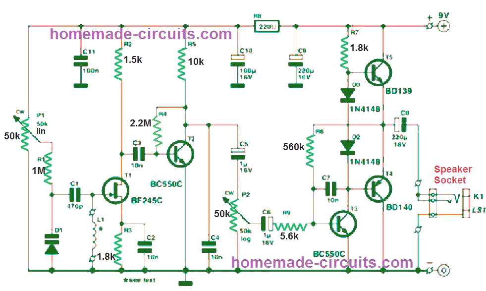
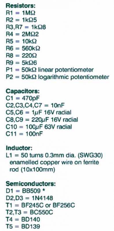
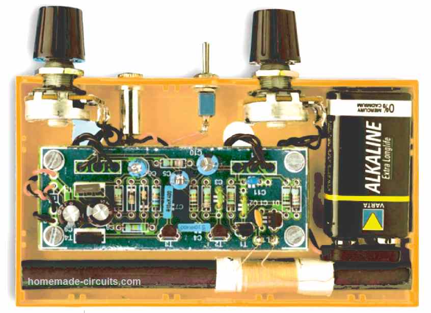
Image of the Built TRF Receiver Prototype
The antenna coil L1, the capacitor C1, and the diode D1 form the TRF MW receiver circuit or the main tuned receiver circuit stage.
C1 is a varicap diode whose capacitance varies depending on the voltage across it.
When the P1 is varied, it causes a voltage variation across C1, which in turn causes the tuning of the receiver and catching a various radio frequencies depending on the resonance formed by the C1 and L1.
Therefore varied P1 of the TRF receiver circuit allows to select the desired stations from the available incoming MW bands.
T1 and T2 along with the associated parts form the demodulator and the preamplifier stages, where T1 demodulates the resonant tuned frequency from the L1/C1 stage such that only the audio section is allowed to pass while the other unwanted voltages are blocked.
This tuned audio signal is fed to the preamplifier stage formed by T2 and the associated parts.
The pramplified radio audio is sent to the base of T3 via P2 and C6. P2 helps to set the volume of the output, and therefore works like a volume control pot.
The transistor T3 further amplifies the audio signal and forwards it to the power amplifier stage built around the transistors T4 and T5.
The T4, and T5 stage along with the other associated component form a nice little 1 watt transistorized amplifier that sufficiently amplifies the TRF audio signals, and feeds it to the attached loudspeaker.
The tuned MW radio output is thus effectively reproduced on the speaker loud and clear.
MW Radio Circuit using IC 4011
The circuit demonstrated below can be used like a simple MW receiver structured around the 4011 CMOS IC.
The four gates inside the 4011 IC package are configured as linear amplifiers by hooking up their inputs one after the other and by creating a negative feedback.
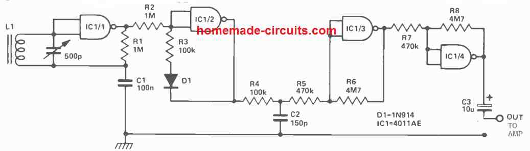
The antenna coil L1, can be built by tightly winding 80 turns of 22 SWG enameled copper wire over a 3/8" diameter ferrite rod, and this works like the pickup coil.
The L1 is tuned through the 500pF trimmer and tank circuit tus formed is referenced to earth at the radio frequency by C1.
The high input impedance, offered by IC1/1, provided to the tank circuit guarantees that the damping factor is kept to the minimum, which causes the MW receiver circuit to be highly selective.
The output from the IC1/1 geneartes an amplified RF signal which is transferred to IC1/2 for the detection function.
The unwanted RF frequency generated at the output of the detector is eliminated by the low pass filter created by resistor R4 and capacitor C2.
The output audio signal is subsequently provided to an amplifier constructed around IC1/3 and IC1/4.
The current consumption of the MW radio circuit's is around 10 mA while powered through a 9 V supply.
Remember that the IC used in this design has to be a 4011AE and not the 4011B whose input protection circuitry could prohibit it from running in the linear mode.
Super Regenerative Radio Receiver
The next circuit depicts our final receiver circuit, which is a solid-state adaptation of Major E.H. Armstrong's well-known regenerative receiver.
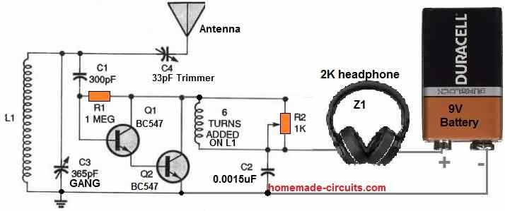
The regenerative receiver ruled throughout its age in radio history and did so until the Major introduced his superheterodyne receiver circuit.
The majority of modern commercial radios are designed using the fundamental superheterodyne architecture.
The antenna coil L1 has 50 turns of 22 SWG super enameled copper wire over a 3 inch long former having a diameter of 2.5 inches.
The other coil with 6 turns in wound over the 50 turns of L1, with a layer of insulation tape in between.
In order to reduce the stress on the tuned circuit, the two BC547 transistors are coupled in a Darlington high input impedance circuit topology.
Tuning the desired radio stations is carried out by C3 and C4. The positive RF feedback is controlled via potentiometer R2. The regeneration control, which also controls the receiver's audio output, is more usually referred to as a potentiometer when it is used in this manner.
In case the receiver seems unresponsive and only faint signals are being received, consider swapping the 6-turn feedback coil's terminals.
That could be all that's required to make the circuit fully functional and active.


Questions & Answers
dear sir.china has developed ‘pen types pocket keeping radio with attachment through hearing wires buds can you know the interior design the electronic items for radio hearing through wires if please kindly give me schematic sketch of inside parts of that pen radio.sir.thank you.
Hi Narsimhan, you can try this design:
https://www.homemade-circuits.com/wp-content/uploads/2026/04/simple-am-radio-circuit-using-IC-TA7642.jpg
hello, why can’t i use a bread board for the first am radio?
On breadboard the connections could be unreliable, with long connections, causing signal loss.
In the article :
Simple High Performance MW Receiver Circuit, use has been made of exotic components.eg ZS 140 and ZS170 , being each a diode.
the text goes on an says that the diode can be replaced by an 1N 4148 diode. It does not tell to replace both diodes by the same modern version. Can you confirm that both , the ZS140 and the ZS170 can be replaced by the 1N4148 diode?
You can replace both diodes with OA79 or 1N34A
But please do not use 1N4148 unless Vf is not critical…you can initially try 1N4148, if it does not work correctly then please go for the above alternatives…
My dears it is time for CRYSTAL RADIO RECEPTION starting from UHF – FM modulation to shortwave and AM broadcasting. Using the new generations of 3SK143-Q transistors and BAT85 diodes…
We can discuss about new schemes and unconventional radio reception systems and diagrams.
Sounds great, thanks for your interest in this subject. We can definitely discuss it if you have the schematics..
hi
Swag could the simple high performance mw reciever work with out ext antenna.also could i run a 8 ohm speaker instead of 35 ohm
Hi Wayne, It depends how strong the radio signal are, if hey are weak then an antenna might be required.
8 ohm speaker can be used, if the TR3, TR4 are replaced with 22N2907 and 2N2222 transistors respectively..
And if I want to keep up with the original design, where could I possibly order a loudspeaker of 35 Ohm!
35 ohms is not critical, you can try a 60 ohm also, or any other similar…
I would like to make a regen radiowhich will intercept allthe mwstation in india
You can get the circuit on this page:
https://www.homemade-circuits.com/tuned-radio-frequency-receiver-trf-circuits/
hi swag
can a oscilloscope display am signal from antenna tuned cct.all i can display is a 50 hertz signal can i get rid of it somehow?
Hi Wayne, an oscilloscope cannot be used to detect signals from antenna, because antenna signals are too weak too be detected by an oscilloscope.
thanks 👍
hi swag
simplest am radio not working,what voltages shouldi expect on Ti and T2.also what is the best way to test signal strength of tuned circuit?.all i can hear is faint scratching sound in speaker when i turn potentiometer
Hi Wayne,
The 1st circuit will be able to amplify AM signals only if the radio station is in a close vicinity and receiving signals are strong. If your radio station is far away then this circuit will not be able to catch and amplify the signals.
Initially you can try replacing the speaker with a headphone or an earphone to detect whether the circuit is capturing any radio signal or not.
I am not sure about the EBC voltage levels of the transistors in this circuit, however before assembling make sure the transistors are not faulty, you can get them verified with an good multimeter first.
hi swagatam
this circuit doesnt have a LM386.its the 2 transistor reciever bc547 and 2n2222 with speaker and ferrite rod antenna. would it drive a 8 ohm 2w speaker
Oh, sorry for the confusion, yes even that circuit will be able to work with an 8 ohm 2w speaker…however you may have to experiment with the collector resistor of the 2n2222 transistor for optimal sound volume…
hi swagatam
would the circuit, simplest AM radio circuit, drive a 8 ohm 2w speaker
Hi Wayne, yes lm386 ic can drive an 8 ohm 2w speaker
Hello! I am building the first radio design here. How important is the exact ferrite coil — what size ferrite rod are you using, what type of wire, and how many turns exactly? I think mine might be too small at the moment.
Also, what type of gang condenser / trimmer is that? I have a 25-600pF variable capacitor. Would that work? Do you possibly have a link to the correct one I could buy?
Thank you so much!
Hello,
I wouldn’t recommend building the antenna coil yourself instead you should buy it ready-made.
You can search for “buy medium wave radio ferrite rod antenna coil” it should give you some good buying options.
Your 25pF-600pF Gang capacitor will work for the mentioned application.
Or you can buy it from any online store, just search for “buy GANG variable capacitor for AM FM radio”
Hello, I am making the first radio and I have a question. I have read your replies to previous comments and still am shrouded in confusion.
1. The variable capacitor range is very large, and in a more specific schematic of the first radio that you provided at this link https://www.homemade-circuits.com/wp-content/uploads/2020/03/simple-AM-radio.jpg the variable capacitor is 500 picofarads. This is kind of big for a small radio? I have consulted an engineer who says so. I am new to making these things entirely so assume I know little to nothing, even the units of measurement.
2. For the antenna coil the schematic labels one side as 60 Wdg and the other 5 Wdg. I looked online to buy one but cannot seem to find one that has two sides with separate amounts of Wdg (which in my research I found to be the number of windings). Also, many have the unit uH which I believe to be the inductance value of the coil, but when I looked up what 60 Wdg would equate to it was 36 uH which was much lower than I saw online. Please provide a specific coil (maybe a link to something I can purchase on amazon) that would work.
3. I want to add a speaker that uses a potentiometer (amp) that can connect the radio to the potentiometer where the potentiometer will control the volume. If I use https://a.co/d/3N5YQbv would that work?
4. Why would the first radio not work on a bread board??
Thanks kindly.
Hi, I think you should try searching with the following key phrase on Google:
“Buy AM radio antenna coil”
You might many online buying options.
The variable GANG capacitor is correct and is the recommended type for all AM receiver antenna coils. It may not be compact but it is right one.
The amplifier unit you have linked will work with the first circuit above, however I would recommend the more universal type of amplifier design using LM386, such as this:
https://www.homemade-circuits.com/ic-lm-386-datasheet-explained-in-simple/
Hello thank you for the response. I have another question, what does the P1 stand for? Is this a potentiometer? Does this control the volume? Thanks again.
It can be a potentiometer or a trimpot (preset), yes it is used as a volume control or gain control in the first diagram…
OK, thank you. Other question, if we use a BC549 B transistor instead of a BC549 C transistor, what would the difference be? How about a BC550 C instead of a BC549 C? I looked it up online and for the 550 it says that the transistor collector and transmitter pins are swapped, so would we swap them?
The difference is just about the collector/emitter voltage values, however the pin connections are exactly the same for all these BJTs, you can confirm all the data under the following article:
https://www.mouser.com/datasheet/2/149/BC550-888526.pdf?srsltid=AfmBOooFeIqa646FgM9loNeKzb1b4KgzpJuneep9EbD6zRt8tfTHtE7k
Hello, for the first radio are the number of wingdings 65 total with a connection to the middle or two separated wingdings? Also, do we use paper or tape or something else to separate the rod and the wire? I am very confused on this part.
Hi, yes, the winding is a single 60 + 5 turns, using 0.2 mm (36 S.W.G.) super enameled copper wire, the centered tap being pulled between these two winding.
Hard paper will work better as the former for this coil, as it can be made to slide across the ferrite rod for better selectivity and resonance.
Hi Swag,
Suppose I would consider winding myself an antenna coil on a ferritrod, what link would describe best on how to proceed?
Best regards Michel
Hi Michel,
It is given in the above article, in the image which shows 90 turns and 8 turns, you can use that data…
Ok thanks! I was also puzzled with the usage of paper, tape etc. as some authors do but do not explain the how and the why.
Yes, the coil former must be built using thin cardboard, and the coil must be secured with tape…
if I understand well, a thin layer of cardboard needs to be fixed around the ferrite rod? This kind of howto is hard to find. Would this kind of description still be available?
It is a very basic construction and nothing’s critical in this construction. You can use a thin cardboard, or a thick cardboard rolled around the ferrite rod to make the former. You can even use a plastic tube for this.
Thanku so much for your quick response sir????
Sir, BF494 Transistors are not available in our local market… Can I use 2n2222 instead of BF series transistors to make FM receiver or plz suggest alternative of it????
Bhola, the frequency range of 2N2222 is 250 MHz, so i think it should also work, you can try it.
Good afternoon Sir,
I want to make a simple, tiny but sensitive FM Receiver using BF494 Transistors with LM386 audio amplifier IC, workable in 4 to 8 Ohms Speaker… FM stations are 150 Km far away from my House… Sir, may you plz give me the links for schematic circuit diagrams of this????
Regards????
Good afternoon Bhola,
You can try the third circuit from this article:
https://www.homemade-circuits.com/make-this-simple-fm-radio-circuit-using/
However, 150 km is too far away, I don’t think this small FM receiver would be able to catch the signal from this distance.
Hello Sir , In the uppermost AM receiver circuit diagram (In which 2 Transistors BC547 and 2n2222) are used, can we connect diy audio amplifier to make it’s voice loud?
If yes, then how can we add? Plz reply????
Hello Bhola, yes that’s possible. You just have to replace the speaker terminals with potentimeter outer leads, then use the center lead of the pot to connect with the amplifier input. The amplifier’s 0V line must be connected with the radio’s zero volt line.
Thank u so much Sir????
You are welcome!!
Do you have a step by step tutorial of how to construct this schematic on the pcb board?
I do not have a step step tutorial, which is not needed actually. There’s nothing critical in the above circuits. You can assemble it normally just as you would do for any other electronic circuit.