In this post I have explained a simple yet accurate spectrum analyzer circuit which can be easily made at home and used for analyzing the audio from a music system or simply as a decorative musical device.
What is a Spectrum Analyzer
A spectrum analyzer is basically a device which is technically used for assessing a frequency source with respect to its strength.
Usually this type of circuit will be quite complicated, however here we are interested in getting a visual display for fun and pleasure therefore accuracy may not be so important.
Here we'll discuss only one channel of the spectrum analyzer circuit, any number of such channels can be built and put together for getting the required results.
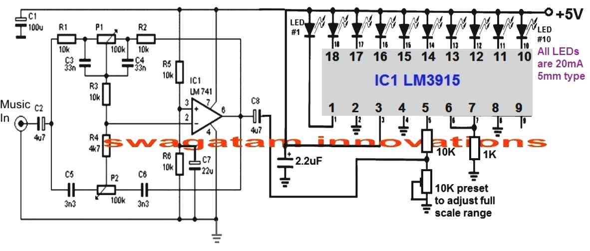
As can be seen in the figure, the circuit of the proposed audio spectrum analyzer consists of two main stages.
Circuit Operation
The left stage can be witnessed to be an active tone control stage while the right side IC LM3915 stage is a 10 stage dot/bar LED display stage.
The tone control stage is a simple bass/treble boost circuit which can be set for acquiring the intended magnitude of signal for a particular fed frequency.
This can be done with the help of the two pots.
P1 may be set for controlling the bass or the low frequency band, while P2 can be adjusted for achieving the high frequency content from the input.
The led driver stage basically responds to a DC level applied to its pin#5.
This response is converted into a sequencing to and fro movement of the LED connected at its outputs.
For example, at voltage levels around 0 and 2, the first three or four LEDs would respond creating a up/down dancing movement, the subsequent LEDs would respond in similar fashion as the input voltage rises at pin#5 of the IC.
How to Set the Controls
The active tone settings decide which frequency level is allowed to get past to the output or amplified to the output of C3.
Suppose if you adjust P1 such that only frequencies within 200 Hz are allowed to pass, the LEDs will produce maximum rise and fall only for these frequencies, and if the music content lacks these frequencies will result in a lower rise or fall in the sequencing.
Similarly you can adjust different frequency ranges for the additional channels in order to achieve the intended fluctuations over the connected LED driver output.
You can make 3 of these or may be 30 of these, just arrange them serially, adjust the pots as per the required specs and see the LED bars dazzle in a up/down motion producing a stunning audio spectrum graphic analysis.
Circuit Diagram
Parts List for the op amp stage
- R1, R2, R3, R6 = 10k 1/4 watt 5%
- C1 = 100uF/25V
- C2 = 4.7uF/25V
- C3, C4 = 33nF/50V
- C5, C6 = 3.3 nF/50V
- C7 = 22uF/25V
- C8 = 4.7uF/25V
- IC 741
Parts List for the LM3915 stage
- 10k, 1k, 1/4 watt 5% = 1 each
- 10k preset = 1
- 2.2uF/25V = 1no
- LEDs 5mm 20mA, color as per specifications = 10 nos
- IC LM3915


Questions & Answers
Hi, I wish to make a circuit with 20 leds around a volume taper where the leds lit progressively one by one when rotating the taper , do you have idea what circuit is suitable for this? I want this for a DIY amplifier with usual 2gang potentiometer 6pin, 20k or 50k
Hi, it may be possible, but the problem is that the LED driver integration cannot be done directly with the volume control potentiometer, because that can interfere with the audio quality and cause distortions.
If you are trying to indicate the volume level with respect to the potentiometer adjustment, then I think the LED indication can be derived from the speaker terminals which will be directly proportional to the rotation degree of the potentiometer.
Thank you so much for your quick reply! The solution I have for this is the double stereo taper on same or common axle , 6 pin used for amp and other 6 pin or 3 pin used for led circuit. They are separate pots on same axle without any interference .
Ok great, in that case it may be easy to accomplish the required idea. You can try the following design and let me know how it works:
Hi, I just did it quick on a breadboard and it works but not in intended way ,the leds are lit progresively but same leds on both led bars 10steps; I want to fill completely 1st bar and then fill the 2nd bar total 20 steps.
Thanks again,I am sure it is a small modification from here .
Thanks for the update!
Can you please open the following datasheet of the IC LM3915 and check the diagram named “Extended Range VU Meter”?
https://www.mouser.com/datasheet/2/405/lm3915-443929.pdf
I think this should be the appropriate diagram for your application.
The “10V full scale” input is the point where you need to configure your potentiometer.
Let me know how it goes?
Hi,I did as on datasheet, the problem is when 1st bar lit 5 leds then start to lit the second bar same time with other half of 1st led bar, from 500 ohm pot only small adjustment could make so changed for 20k so the 2nd bar start to lit when 8leds are lit on 1st bar…changed then with 50k pot so almost perfect but second bar start to lit before last led on 1st bar…and one more odd thing is for 1st bar now the leds are lit more quickly one after another and on the 2nd it comes to normal… it is still some imbalance between led bars and want to lit completely the 1st bar and then to start lit the 2nd .
Hi, did you adjust the reference preset precisely?
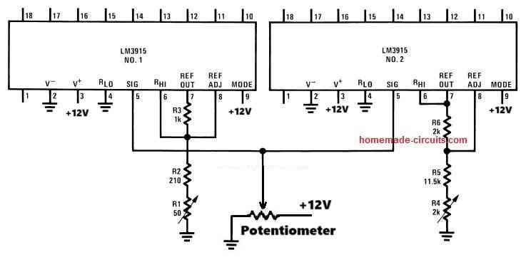
Alternatively you can configure to separate LM3915 LED modules and adjust the input levels at pin#5 with independent presets such that when the first IC LEDs reach the full level (pot rotation at midway), only then the second IC LEDs start to illuminate.
This independent arrangement migjt actually enable adjusting the range more accurately and as desired.
This is awesome, probably the simplest Spectrum Analyzer schematic I’ve seen on the web so far, thank you. I’m no engineer, no formal training, only self taught, but I’m picking up a few things. A few things I did notice though, so I have a few questions:
1. Have you actually built this? Would this be for line-level audio input or post-amplified (speaker line) output? Because I don’t see a gain potentiometer or a buffer circuit prior to the op amp filter.
2. If you HAVE built one, can you provide a video of it in action?
3. In the diagram just under C1, is that supposed to be a ground? 100uF is awful big, what purpose does it serve? Is that an electrolytic or non-polar cap?
4.I ASSUME that R5 to power positive and R6 to ground serve as voltage reference dividers for the + side of the op amp, correct?
5. Your parts list doesn’t say which capacitors need to be polarized DC electrolytic (for the LED driver) and which need to be non-polarized (ceramic or film) for the AC audio bandpass filters. For newbs who have never built one and/or limited knowledge of electronics, not knowing this and building it using all electrolytic caps (i.e. the cheapest way) would result in a dead board that doesn’t light up or do anything. Could you edit this to clear up any confusion please?
6. In nearly all the other Spectrum Analyzer (& color organ) schematics I’ve seen include a diode between the op amp filter(s) and the LED drivers, yours doesn’t have one. Isn’t this bad for a DC LED circuit? Wouldn’t that cause flickering? Is this an oversight you missed?
7. And finally, would this be considered a Butterworth, a Chebyshev or a Bessel type filter? I’m trying to wrap my head around this. I want to use fixed rate resistors to create a solid state bandpass filter (no “tuning” required) and I can’t compare it to any type of online bandpass filter calculator to compute the values I need for the frequencies I want. I get it, adjust the high pass and low pass to tailor the bandwidth to display the desired frequencies, but without a tone board or an oscilloscope, it makes it hard for a newby to dial it in. I know the frequencies and bandwidths I want, but not the component values, and without knowing the kind of configuration this is, I’m unsure of which equations I need to calculate the desired values of caps and resistors.
Also, your parts list fails to mention the 100K potentiometers.
Thanks in advance for your response, I eagerly await your reply.
p.s. Sorry for the long winded comment.
Thank you very much, yes the concept is actually very simple.
The op amps are configured as tone control, and the LM3916 IC is configured as a VU meter
The op amp are used for allowing a specific frequency to the VU meter, and the VU meters translates it into illuminated LED levels, indicating the approximate frequency range.
The VU meter actually detects the average DC voltage level of the frequency, with lower frequency this level increases and the increasing frequency the DC level decreases.
So this the basic concept.
The components are not critical, all the parts are ordinary and any type or specification will work
Hello Swagatam,
I have built now times 3 channels on the plug board !
It works so far quite well ! You can see that different frequencies are displayed !
I have connected it via the AUX OUT of the CDPlayer ! But there are CDs where the output is simply overdriven!
I connected it to a radio where there is also an AUX OUT, but on the radio the level is very weak maximum 3 LEDs light up !
How can I change this ?
Should I use a small preamplifier with adjustable potentiometer ?
And again to the frequency alignment, I downloaded a frequency generator for Windows !
There you can set any frequency, for example 5khz !
Unfortunately I don’t have an oscilloscope, but a multimeter that can measure frequencies !
Have applied the measuring tip to pin 5 of the LM3915 and turned the potentiometers, always shows me only 5khz !
What am I doing wrong ?
Please, please help me !
Thanks in advance Greetings Thomas
Translated with http://www.DeepL.com/Translator (free version)
Hello Thomas, the circuit is basically a low range audio power meter. The frequency is converted to voltage at pin#5 of the IC which is reflected on the output LEDs.
With high bass the music is more powerful, compared to high treble music. With high bass the voltage at pin#5 will be relatively higher than a high treble music.
So this is the basic principle of this spectrum analyzer. You can Remove the Lm3915 from the 741 bass/treble output and connect a DC V meter in its place. Apply music at the input and check whether or not the voltage increases with bass control set at high, and decreases when the treble control is increased. This will prove whether your op amp tone control is working correctly or not.
You will have to set it up by understanding the concept thoroughly, otherwise it may be difficult for you to complete this project.
The basic idea is, bass means higher power, treble means lower power, this is exactly what the LM3915 will detect and show.
You can use a LM386 amplifier at the input side to boost lower input signals
Hello Swagatam,
Thanks a lot for the response !
Sorry if you receive this message twice!
Wasn’t sure whether to reply or reply to my email ?!
Could you send me that in the form of a circuit diagram, I don’t really understand it!
Or sketch?
Many thanks in advance !
Next time I’ll send pictures, maybe a video!
Greetings Thomas
Hello Swagatam,
I’m slowly desperate!
The circuit you sent me only works well with direct input from the CD player!
But not through the filter stage!
If I omit the diode 1N4148 then it works to a certain extent, but not nice!
It flickers a lot!
I used a potentiometer for the 10K resistor, but unfortunately no great effect!
What am I doing wrong ? Perhaps cascading the LM3915 is not correct? Could you make a circuit diagram of this for me? I want to connect 4 pieces so 40 LEDs!
I set it up again on a breadboard to quickly change components! If several people have already set it up, should it work?
I hope you can help me ?
In Advance thank you !
Greetings Thomas
Hello Thomas,
you must do it in the following way:
hello Swagatam,
I’m slowly getting embarrassed to ask so often, please again sorry!
First of all, thanks for the circuit diagram!
That’s roughly how I thought it, but I wasn’t sure!
Is the 10K a potentiometer or just a normal resistor?
Can I also use another capacitor? I don’t have a 1microfarad right there!
Thank you very much in advance for your support!
Greetings Thomas
It’s fine Thomas,
The 10k is a preset.
You can use other capacitors also. Smaller values will give lower hold time and vice versa.
Hello Swagatam,
Thank you for your patience !
Presetting the 10k resistor?
Does that mean I need a different one for each channel? but Poti ??
I’m totally confused now! I thought that you can set the frequencies via the pots P1 and P2?!?!?
I understood that with the capacitor, I have to see which one is best!
Please don’t be angry ,,,, I’m not a real electronics technician, but I always want to educate myself because it’s a nice hobby!
Thank you in advance for your understanding!
Greetings Thomas
Hello Swagatam,
Thanks for the feedback !
I have now ordered capacitors, had 2.2 microfarad capacitors, it was pretty good!
Now I’m waiting for 1 microfarad capacitor!
I will contact me again when I have finished the 2nd and 3rd channel to report!
But it can take several weeks!
Greetings Thomas
No problem Thomas, thanks for informing!
Hello Thomas, the 10k at pin 5 of the IC LM3915 is supposed to be a preset. The P1, P2 associated with the op amp can be pots
Hello,
Can you please give me the parts list of this wiring diagram?
I would like to recreate it!
Do you have a demo video of this circuit?
I would like to build a 10 channel audio spectrum analyzer from it, but with 40 LEDs per channel!
You can cascade the LM3915!
Thank you in advance Greetings Thomas
Hello Swagatam,
sorry for asking again!
The resistance 1M at pin 5 on the LM3915 is apparently too big, the LEDs all light up when switched on and do not go out except for the first 3 LEDs!
If I use a smaller resistor, for example 10 K, then all LEDs go out!
Is that correct ?
Another question, how do I have to set the frequencies?
For example 1 khz?
Do all LEDs have to light up?
As I said, I set up 1 channel on the breadboard as a test!
I had a test tone from a 1 khz fed in via the cell phone! I can turn LEDs almost to full deflection with the potentiometer!
I hope you can help me again?
best regards Thomas
Hello Thomas, yes 1M does not look correct, you can try a 10k or 1k preset in place of the 1M, and check the results.
The bass output should cause the LEDs to go higher up on the LED bar, while for the treble response it should be on the lower side.
Once you adjust the 10k preset appropriately, the results should be apparent for the different frequencies.
How the LEDs light up and up to what range across the bar will depend on the bass, treble adjustment, the input frequency,and the volume of the frequency.
Hello Swagatam,
First of all thank you very much for the reply !
That with the 10 K Widerstandd is so far quite good!
I would like to ask you to build the circuit on a breadboard and demonstrate how to adjust the potentiometers. A video is the easiest way to explain something. Or do you know someone who has built the circuit and can perhaps post a video ?
Since I want to build 10 channels with 40 LEDs per channel is already a lot of work and want to experience no disappointment at the end that it does not work so well!
For a response I would be very happy and say now in advance many many many thanks!
Best regards Thomas
You are welcome Thomas, if time permits I will surely try to create a video for this project, however, testing and understanding this project is actually very easy.
The idea is that, lower frequencies (high bass) will produce more RMS voltage compared to high frequencies (high treble)….these responses will be translated accordingly on the LM3915 output LEDs, since the LED illumination is directly proportional to the RMS voltage fed at pin5.
You can completely remove the op amp stage and feed the pin5 with a 100 Hz frequency and 1kHz frequency separately and check the responses on the LEDs, this will make things clear regarding the basic working of this spectrum analyzer. Make sure to send these signals via a diode.
Hello Swagatam,
First of all, many thanks for the reply!
Well, then I can use my ICs!
I have tried it with high notes and low notes, the result is that with deep notes the deflection is higher than with the high notes!
In the meantime I finished soldering a channel made of 40 LEDs. Is a lot of work, but looks good!
With just one channel you don’t see the effect, so the second channel should be soldered! But what I generally notice is that the reaction is very fast and not soft or slower! like here:
I wrote to him once, but unfortunately no answer!
He uses completely different components!
Is there one less slowing down on your circuit?
In Advance thank you !
Would you mind sharing the picture of the prototype thank you
Sounds great Thomas, glad you are making some good progress.
The delay effect can be easily added with the following small modifications.
1) Connect a 1N4148 diode between the C8 output and the center of the 10k preset. Cathode will go to the 10k center lead.
2) Connect a 2.2uF capacitor between the 10k preset center lead and ground
Hello Swagatham,
Have now soldered the first filter !
When inserting the IC I found out that I have no LM741, but a UA741CP !!!!
Have looked times, should be equivalent ?!
I hope you can tell me about it, otherwise I have to order again the right LM741 !”
In advance best regards
Thomas
Hello Thomas,
Both are one and the same as far as functioning is concerned. So you can use the UA741CP also without issues
Hello Swagatam,
Thanks a lot for the response !
I’m looking forward to you making a video of it!
In the meantime, I set up all 10 channels, it’s a lot of work!
Perhaps you have already made a video!
First of all, have a nice Christmas and best regards
Thomas
Thank you Thomas, and wish you all the best with the project, and a Merry Christmas to you!
Dear Swagatham,
thank you for the parts list!
I have now ordered all the parts!
The project will be tackled in the next days and weeks 🙂
No problem Thomas, wish you all the best with the project!
Hello Swagatam,
I built the circuit according to the circuit diagram!
So one channel, if I now want to set this channel to 1 kHz, for example, only 2 LEDs light up when I turn the potis!
I have already used other resistors on the LM3915, but without change!
I tried to set it with the cell phone with a 1 khz test tone!
I tried to connect it to the line out on the CD player, there are only a maximum of 2 LEDs!
I hope you can help me !
Greetings Thomas
Hello Thomas, the LED response will be depending on 3 things, frequency, volume and the pin5 preset adjustment, please make sure these 3 parameters are appropriately optimized for getting the relevant responses. You can try increasing the preset value at pin5 to 100k and check the response….
Hi, I have updated the part list
sorry I do not have a video for this project at this moment
yes cascading of LM3915 can be tried
Dear Swagatham,
Do you have any Automatic Gain Contrle(AGC) or Automatic Level Controle(ALC) circuits. If we add an AGC/ALC circuit with the Audio Spectrum Analyzer circuit, the LED display can work irrespective of amplifiers volume control setting.
Eg:- If I take audio input from speaker terminals (such cases when a preamplifier output is not accessable), the displays beauty will lose when we increase and decrease amplifiers volume.
I googled, and find two simple circuits, but they use dual polarity supply. I am looking for a single supply and simple circuit.
Regards
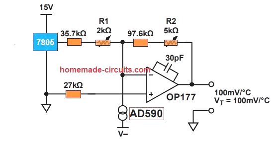
Dear Anil, I found the following circuit after some searching, you can try it:
Dear Swagatham, many thanks for the simple AGC circuit, exactly matching with my request.
Please clear my following doubts
1) T1, T2 and D3, D4 values are not shown.
2) Can I replace D1, D2 with 1N4148….?
3) If I use this AGC with the above Sectrum analyzer circuit, where should connect it for best permormance….? I mean, before the TONE CONTROLE section or after the TONECONTROL section….?
Thanks in advance
Thanks Anil, you can use 1N4148 for all the diodes, because the reverse recovery of 1N4148 is also very fast at 4ns.
T1/T2 can be BC547
You can connect it before the tone control circuit, that is between the main audio source and the tone control
Thanks dear Swagatham for your lightening fast reply.
It’s my pleasure Anil!
Hi Swag,
Building a 10 level Spectrum Analyser, with 10 identical circuits, in order to setup the correct frequencies in each circuit, where in the circuit do I put the tips of a Frequency Meter so that I can ajust both P1 and P2 to read the frequency set for each?
Best Regards.
Nélio Abreu
Hi Neilio, I think the best place to connect the frequency meter is across the 1M resistor associated with pin#5 of LM3915
Hi Swag,
Thanks.
Best Regards.
Nélio Abreu
You are welcome!!
Got it….. -:)
just for sure ,what will be the base resistor for 12v,1.5amp load(like no of leds in a channel……
Have a good night…. till tomorrow 🙂
K. Kausik
base resistance can be calculated using the following formula:
R = (Supply – 0.6)Hfe/Load Current