In this post I have explained about a 5 simple siren circuits, using Arduino and also with ordinary components such as transistors and capacitors yet is able to produce an alarm sound at an excruciating level.
The idea was contributed by "Abu-Hafss"
Deeper in the article we also learn to make an advanced Arduino based design with adjustable and customizable tone features.
1) The Design
This simple car siren circuit design explained here uses minimum number components and yet is able to produce an ear piercing alarm sound each time it's switched ON.
The device is normally used as a car reverse horn, although it can used for any other relevant application too, depending upon the user's preference.
In the automobile field this siren is also popularly know as the "Mega Siren" due to the massive decibel level it generates.
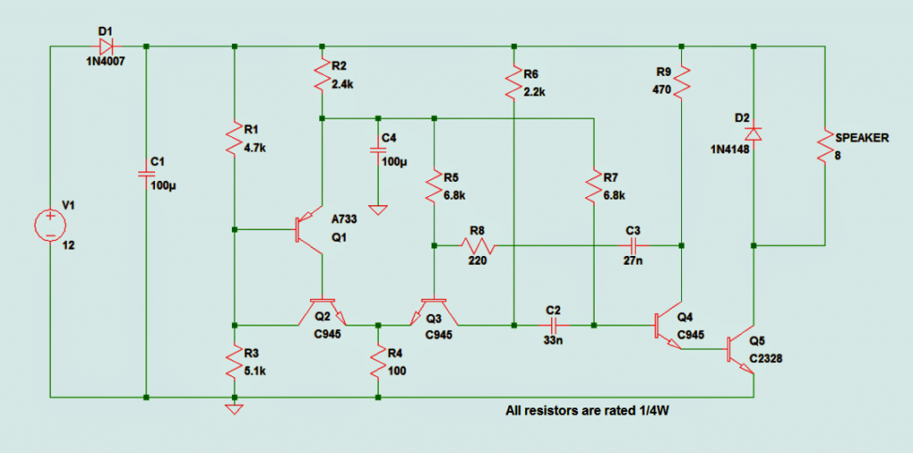
The schematic details and other related info of the proposed car siren is presented below,which were furnished by Mr. Abu-Hafss, who is one of the dedicated readers and contributor of this blog.
Circuit Diagram
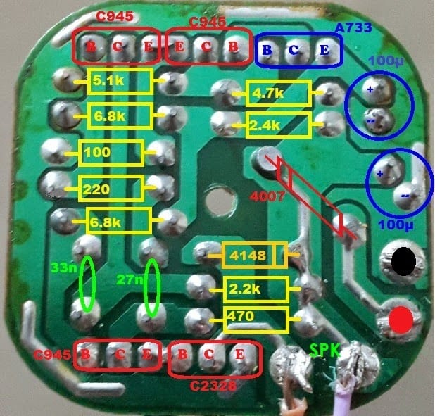
PCB Layout
The following request was also attached with the above files in the email from Mr. Abu-Hafss.
Dear Swagatam,
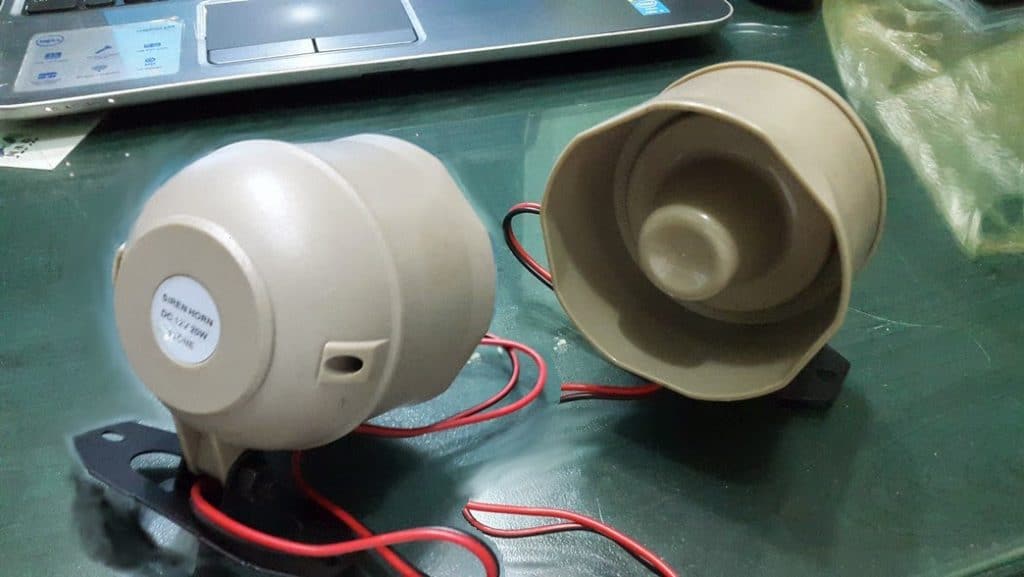
Attached, please find a photo of a car 12V-20W siren which has really ear-piercing sound. I opened it and found a small PCB as attached.
I have interpreted the PCB into schematic as attached. My concern is to use the amplifier section for some other 15-20W application.
Frankly, I do not have practical experience of audio amplifiers. I shall highly appreciate your help in this regard.
Best regards
Abu-Hafss
As per the above request, the amplifier section of the car siren is cheap and powerful (@ 20watts) and possibly could be used as an amplifier module for other applications requiring a cheap but powerful amplifier alternative.
Analyzing the The Design
Studying the given diagram it appears that the stage comprising Q4, Q5 is only responsible for the amplification, the remaining sections are for generating the siren frequency for the Q4, Q5 base.
The stage forms a powerful Darlington transistor amplifier stage with an extremely high gain (in the order of 1000 and more)
Since the amplifier design is too basic, it might not be suitable for generating or handling Hi-fi music or frequencies above 4kHz.
Moreover the transistor in the process could dissipate a significant amount of heat causing the consumption to be higher than the normal Hi-fi amplifiers.
Therefore, although the amplifier incorporated in the above car siren circuit is cheap and simple it cannot be efficiently implemented for producing movie songs and melodies which involve frequencies up to 15kHz. However, it can be effectively used in units such as horns, bells, alarms, security systems etc.
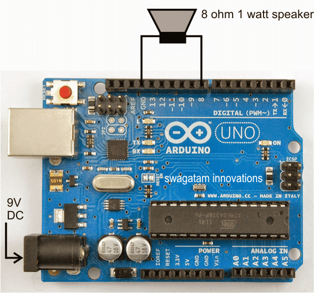
2) Generating Siren Sound with Arduino
The following Arduino based siren sound generator circuit can be used for generating the pitch perfectly imitating a typical siren sound and can be customized to produce many different siren effects simply by making relevant modification in the sketch.
A siren sound, as we all know is a loud noise generated through a device designed for producing this sound either through a mechanical approach or through electronic circuits.
Siren sound generator devices find many useful applications and are used in emergency service vehicles like in police and ambulance vehicles, and also in fire brigades etc.
The discussed configurable siren enables a connected speaker to produce a custom siren sound.
Basically there are two types of siren sound generating equipment, viz pneumatic and electronic.
Pneumatic systems employ air pressure forced through an appropriately dimensioned pipe for creating the sound, while electronic equipment are more sophisticated, using loudspeakers or piezo devices for generating the relevant sound at any desired rate and pattern.
Electronic sirens are more flexible, customizable and offer more variations and are extremely efficient.
Types of Siren Sound
A Siren sound can be of many different types, a few common types are the police, ambulance, and the fire siren, others could be in the form of mega sirens as used in car horns, some are fast police siren tunes, another type could be ear piercing such as used for neutralizing mobs, a few could be in your cell phone for alerting while a new message is received.
Therefore, the range could be too extensive and the proposed Arduno alarm circuit can be customized as per the users personal wish and preference for achieving the wished siren sound.
Code sketch:
/*
Siren
A configurable siren for Arduino, requires an 8-ohm speaker attached to
pin8 and ground. For high amplification use a transistor driver with pin8
//Copyright (c) 2012 Jeremy Fonte
//This code is released under the MIT license
//https://opensource.org/licenses/MIT
 const int pitchLow = 200;
 const int pitchHigh = 1000;
 int pitchStep = 10;
 int currentPitch;
 int delayTime;
 const int speakerPin = 8;
 void setup() {
 currentPitch = pitchLow;
 delayTime = 10;
 }
 void loop() {
 tone(speakerPin, currentPitch, 10);
 currentPitch += pitchStep;
 if(currentPitch >= pitchHigh) {
 pitchStep = -pitchStep;
 }
 else if(currentPitch <= pitchLow) {
 pitchStep = -pitchStep;
 }
 delay(delayTime);
 }
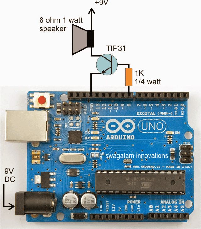
Arduino Wiring Diagram with Speaker and Supply Input
Video Demo:
Using a BJT Stage for Greater Amplification
For high amplification, the above set up can be modified as per the folowng connection diagram:
Modifying the Code
Upon Testing I fund the siren sound from the Arduino not very pleasant, and had slight distortions. I experimented with the code, and finally made it extremely smooth and pleasant to hear. Here's the improved for you:
//Improved by Swagatam

 const int pitchLow = 200;
 const int pitchHigh = 1000;
 int pitchStep = 10;
 int currentPitch;
 int delayTime;
 const int speakerPin = 8;
 void setup() {
 currentPitch = pitchLow;
 delayTime = 5;
 }
 void loop() {
 tone(speakerPin, currentPitch, 20);
 currentPitch += pitchStep;
 if(currentPitch >= pitchHigh) {
 pitchStep = -pitchStep;
 }
 else if(currentPitch <= pitchLow) {
 pitchStep = -pitchStep;
 }
 delay(delayTime);
 }
You can also play with the const int pitchHigh = 1000;and increase to to 2000 for increasing the siren length, which is relevant to police sirens.
3) Police, Ambulance, Fire Brigade Siren - USA Style
The next siren circuit is a 3-in-1 siren, which will produce 3 distinct tones resembling, police siren, ambulance siren, and fire brigade sirens sound.
These can be selected through a 3 pole switch, and simply by toggling the positions of the switch.
The complete circuit diagram for this 3 in 1 siren circuit is furnished below:

4) Siren Using IC 7400
Here's another simple and cheap siren using the IC 7400 that can be used for many different alarm applications.
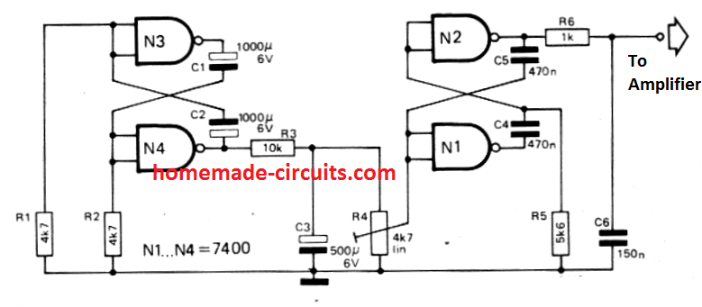
The circuit basically is configured around two astable multivibrators, N1/N2 and N3/N4. The N1/N2 stage generates a 0.2 Hz square wave signal which is coupled to the N3/N4, which causes an up and down swing of the 0.2 Hz.
The resulting siren output is 2 V peak to peak and can be amplified any suitable amplifier for getting a loud siren sound.
5) Siren Circuit using Unijunction Transistors
The indicated loud siren circuit is made up of a pair of unijunction relaxation oscillators. UJT Q1 is configured to generate low frequency while Q2 is wired to produce audio frequency.
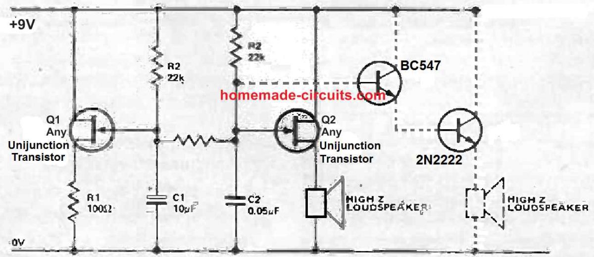
Resistor R3 connects the slow rising voltage over C1, decided by the time constant components C1 and R2, with the audio frequency across C2, established by the time constant of C2 and R4.
The combination results an output where the audio frequency created by Q2 increases in pitch due to the application of the slow rising voltage across C1.
This is applied through the resistor R3 to the time constant network C2/R4.
This generated siren sound due to sharp intensity is able to travel a longer distances away compared to simple continuous siren sounds generated through just one oscillator.
If you want additional amplification you can accomplish it by integrating a couple of transistors in a super-alpha Darlington set up, as indicated in the dotted circuit stage.
R4 resistor shown at the center, must be substituted with a 100 ohm 1/4W resistor.
Hooked up to some pressure mat (through over C2), this specific UJT siren circuit could form a fantastic baby snatch alarm for strollers.
6) Ship Siren Circuit
This circuit will generate a high pitched sound just like a ship's siren.
The design works well using the low power output source for model ships, when the output signal is appropriately amplified through a power amplifier, to produce a loud ship like alarm tone.

The circuit is configured around a multivibrator through the transistors Q1 & Q2, and a low power output stage using the transistor Q3. The indicated speaker is required to have an impedance of around 40 to 80 ohms.
Capacitors C1 and C2 are responsible for the pitch intensity of the siren and with the values shown in the diagram, the pitch of the siren can be approximately around 300Hz.
The Quiescent current of the circuit is quite low and can be ignored.
If you wish to have a much more powerful ship siren sound, in that case you can integrate the Q2 collector output with an external amplifier input through a 1µF electrolytic, in series with a 12k resistor.
7) High Power MOSFET Siren
The next concept shows a simple yet powerful MOSFET based siren circuit.
Tr1 is utilized as a common emitter circuit, with R2 as the collector load and R1 providing base biasing. C3 connects the output of Tr1's collector to Tr2's input (gate terminal).
Tr1's base operates in phase with Tr2's collector, and both Tr1 and Tr2 produce an inversion of the signal. As a result, C2 and R3 offer positive feedback, and the circuit's gain is big enough to create powerful oscillation.
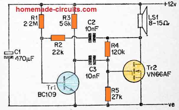
The drain terminal of the MOSFET Tr2 receives an approximately squarewave signal, and the device is turned between hard on and hard off states.
This causes very large current pulses (about 500 mA peak) to be pushed to the loudspeaker, resulting in a very loud siren tone output.
The working frequency is around 1kHz, however it may be adjusted by changing C2 and C3 values.
Varying their values can create an oppositely proportionate change in the oscillating frequency, therefore make sure C2 and C3 have identical vaues.
8) 10 watt Power Siren
This ingenious small design makes use of the most recent developments in semiconductor technology to create a very compact, low-cost, yet extremely powerful alarm-sound generating unit that can be simply integrated into an existing intruder alarm system or equivalent "protection" equipment.
The alarm circuit includes a basic alarm-signal generating stage, which is accompanied by a power amplifier stage. The alarm-signal component of the machine is built around a low-cost CMOS integrated circuit that uses almost no "standby" power.
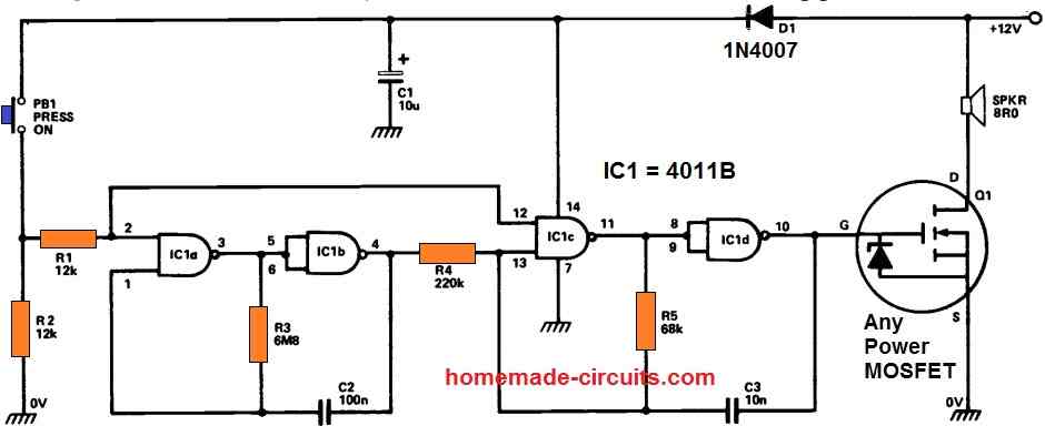
The power amplifier circuit is a true cutting-edge technology, a low-cost MOSFET power FET that uses almost no current while in "standby" mode.
As a result, there is no need for a discrete on/off switch, and the device may be left completely linked to a 12 volt battery supply. IC1a and IC1b are wired as slow astable multivibrators, whereas IC1c-IC1d are connected as fast astables.
Each of these astables are "gated," meaning they may be switched on and off using PB1.
The ICa-IC1b slow astable's output is applied to control the frequency of the 1C1c-IC1d fast astable, and the fast astable's output is supplied to the external speaker through the Q1 MOSFET power amplifier stage.
When PB1 is open, each of the astables and Q1 are inactive, and the circuit draws almost little standby current.
D1 and C1 are utilized to guarantee that voltage spikes produced into the battery supply connections through the speaker do not have a detrimental effect on the astable operations.
It should be noted that the circuit requires an 8 Ohm speaker rated to handle higher than 10 watts.
9) Powerful Siren Circuit using a Single 4001 IC
Basic Working
From a technical standpoint, employing a 12-volt power source and linked to an 8 ohm speaker, the arrangement holds the potential to yield approximately 9 watts of acoustic potency, which, when emanated through a quality loudspeaker, results in a fairly penetrating sound output.
This sonic intensity is hoped to serve as a deterrent, effectively driving away unwelcome individuals from the vicinity, including household pets like dogs, guinea pigs, and tortoises.
Initially conceptualized with caravan security as the central focus, the project necessitated a 12-volt power supply since most caravans utilize a 12-volt lead-acid battery for illuminating their interiors and powering water pumps.
However, it is essential to note that the 12-volt power requirement is not absolute, as the circuit can adequately function with a power supply as low as 6 volts (though with a reduced sound output) and up to 15 volts (resulting in an escalated sound output).
When powered by 6 volts, approximately 2 watts of acoustic power is generated.
The upper limit for voltage, incidentally, is defined by the maximum power that the output transistor (denoted as Q1 in the figure above) can dissipate, which stands at 15 watts, correlating to a 15-volt power supply.
How to Build
Regarding the construction process, as customary for first-class endeavors, readers are offered the option of employing either a printed circuit board or stripboard.
For those opting for PCB construction, the layout, overlay, and wiring specifics are detailed in the figure below.
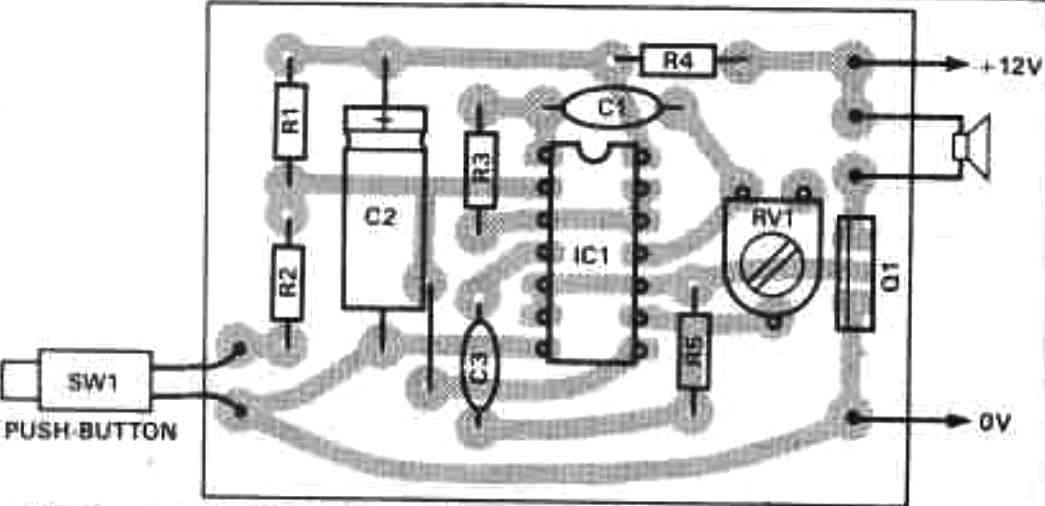
The constructional particulars are quite comparable in either case. Begin by inserting and soldering passive components, starting with resistors and then capacitors.
Notably, capacitor C2 is an electrolytic capacitor that necessitates correct polarization.
Next, proceed to insert and solder the links, followed by PCB pins and an integrated circuit socket if you opt to use one.
PCB pins simplify lead connections after board completion, while an IC socket safeguards against the risk of IC damage due to heat during soldering.
Nevertheless, the IC in question, a CMOS 4001 quad two-input NOR gate device, is reasonably priced, so even if it were to incur damage during soldering, a new IC would likely cost less than the socket itself.
Lastly, insert and solder the semiconductor components, ensuring proper polarization. If an IC socket has been soldered in, the IC can be effortlessly fitted into place.
How to Setup
As for the setup process, it is straightforward.
Initially, connect the leads to the loudspeaker, power supply, and a push-button switch, following the illustrations provided.
Once you are certain that all connections are accurate, adjust preset resistor RV1 to about the midpoint.
With earplugs in place for protection, activate the push-button switch.
Even with earplugs, you will be able to discern whether the project is operational or not.
The inclusion of preset RV1 in the circuit allows for adaptation to different power supply voltages, enabling the fine-tuning of the siren effect to achieve optimal results.


Questions & Answers
Hello admin, can I have a full “explaination of how each opponent works” of the 3rd siren circuit, please? Thank you so much!
Hey, Khac, here’s the reply for yu:
This circuit uses two oscillators to create the different siren sounds.
The right side, with transistors T4 and T5, is a high-frequency audio oscillator. T4 is a small NPN transistor that drives the heavy-duty TIP36 power transistor (T5), which sends strong electrical pulses to the 8-ohm loudspeaker to create the actual pitch you hear.
The left side, with transistors T1 and T2, is a low-frequency modulation oscillator that cycles slowly at about 1 to 2 Hz. Its output passes through transistor T3, which acts as a buffer. T3 alters the base current of T4, forcing the high-frequency pitch to rise and fall rhythmically. Capacitor C1 slows down these changes so the pitch slides smoothly instead of jumping.
Switch S1 changes the siren style by altering the low-frequency section:
In position S1a (Fire Brigade), a large 470uF capacitor (C7) is connected. This makes the pitch rise and fall very slowly.
In position S1b (Police), the switch is open, allowing the circuit to cycle at its natural, fast pace for a rapid wailing sound.
In position S1c (Ambulance), a 1k ohm resistor (R11) is connected to ground, which creates a sharp, alternating two-tone “hi-lo” sound.
Hi Sir.
But in diagram 4 where is the power applied?
Thanks
Hi Rosario,
The positive is applied to pin#14 of the IC and the negative is applied to pin#7 and the ground line of the circuit.
Thanks
you will need an inductor in parallel with the piezo wires…..you can wind 1000 turns of 36 SWG enameled copper wire over a ferrite drum for making the inductor
Is that a normal speaker or a piezo buzzer? It seems to me that the speaker is not a magnetic coil speaker. To receive any sound you might have to use a powerful buzzer.
No, it's a loudspeaker, as we have in radios and TVs.
Dear Swagatam Da,
I constructed the circuit ( image link s14.postimg.org/kgqpm8jpt/siren_circuit.jpg )
according to the schematic as well as according to the PCB but found no sound in 1.5w 8ohm speaker.
Please post a circuit similar to the sound heard in youtube in this topic.
Dear Bubai,
as you can see in the post, the circuit was taken from a working model and produced exactly as is in the original unit….so it should work according to me.
check all the components and the tracks carefully once again, you might have done something incorrect while assembling.
the sound clip was recorded from the original piece presented above.
Hi Swagatam
I intend to use the amplifier only for horns & alarms made by using 555.
Please see the attached schematic. Is it correct or do I need to test the values for the resistor and capacitor?
Hi Abu-Hafss,
It looks OK to me, but a resistor in place of C2 would be more appropriate according to me….the value can be anything between 1K and 10K.