• Skip to main content
  • Skip to primary sidebar

Homemade Circuit Projects

Need circuit help? Post them in the comments! I've answered over 50,000!

Blog | Categories | About | Contact | Calculators-online
You are here: Home / Small Signal Transistor(BJT) and Diode Quick Datasheet

Small Signal Transistor(BJT) and Diode Quick Datasheet

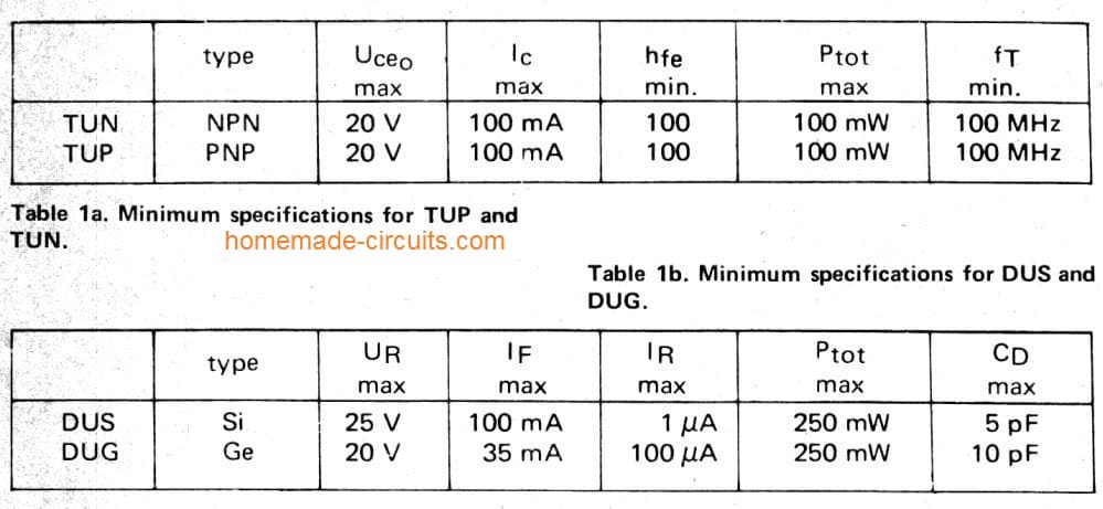
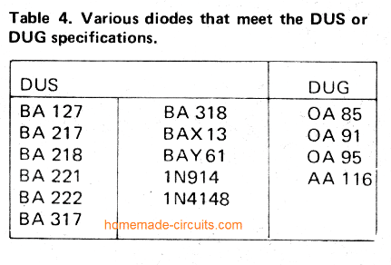
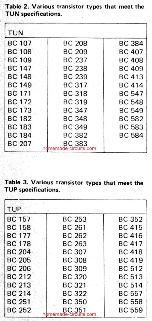
Below are a list of Transistors and diodes marked ‘TUP’ (Transistor, Universal PNP), ‘TUN’ (Transistor, Universal NPN), ‘DUG’ (Diode, Universal Germaniuml or ‘DUS’ (Diode, Universal Silicon).

This indicates that a large group of similar devices can be used, provided they meet the minimum specifications listed in tables 1a and 1b.

universal NPN transistor current and voltage specifications
Universal diode current and voltage specifications
All NPN and PNP transistor small signal type listing
Image2b
Transistor equivalents, wattage and package specifications
Image3

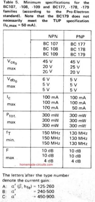
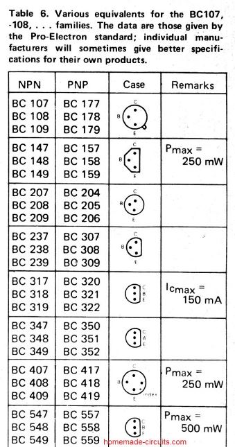
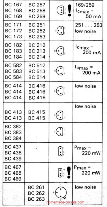
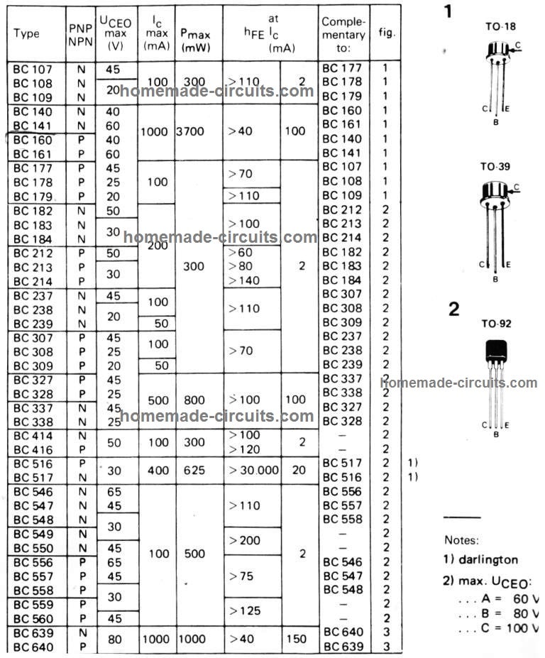
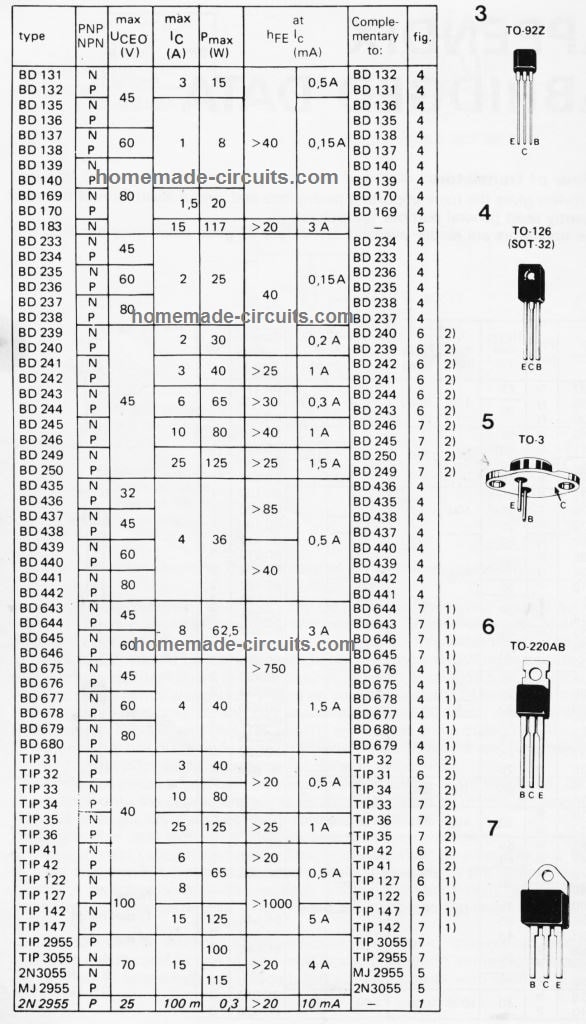
Detailed BJT Datasheet, Pinouts with Complementary Pairs

The following figure shows a vast range of bipolar transistors and their detailed specifications. You can learn about their NPN/PNP polarity, Uceo, Ic, Pmax, hFE, an also regarding equivalent numbers, or complementary pairs.

Datasheet, pinout of all standard  transistors and BJTs
All Power Transistor datasheet, pin details

Bipolar transistors work with four distinctive areas of operation, characterized by BJT junction biases.

Forward-active (or simply active)

The base–emitter junction is forward biased and the base–collector junction is reverse biased. The majority of bipolar transistors are designed to handle the highest common-emitter current gain, βF, in forward-active mode. In such a scenario, the collector–emitter current is roughly proportionate to the base current, but most of the times greater, for small-scale base current changes.

Reverse-active (or inverse-active or inverted)

By reversing the biasing factors of the forward-active region, a bipolar transistor switches into reverse-active form. In this setting, the emitter and collector areas swap their tasks.

Due to the fact that many BJTs are built to enrich current gain in forward-active mode, the βF in opposite form appear to be many times lesser (2–3 times for the standard germanium transistor).

This transistor function is hardly ever applied, typically used just for failsafe situations plus some kinds of bipolar logic. The reverse bias breakdown voltage on the base might be an level of dimension smaller in this region.

Saturation

Having both junctions forward-biased, a BJT acquires saturation mode and makes it possible for high current conduction through the emitter to the collector (or the other route when it comes to NPN, with negatively charged carriers moving from emitter to collector). This method refers to a logical "on", or a shut-off switch.

Cut-off

In cut-off, biasing situations are reverse of saturation (both junctions reverse biased). There exists hardly any current, that compares to to a logical "off", or an open switch in this mode.

Reader Interactions

Need Help? Please Leave a Comment! We value your input—Kindly keep it relevant to the above topic! Cancel reply

Your email address will not be published. Required fields are marked *

Primary Sidebar

Subscribe to New Circuit Ideas

Categories

  • Arduino Projects (87)
  • Audio and Amplifier Projects (132)
  • Automation Projects (17)
  • Automobile Electronics (101)
  • Battery Charger Circuits (82)
  • Datasheets and Components (102)
  • Electronics Theory (143)
  • Free Energy (37)
  • Games and Sports Projects (11)
  • Grid and 3-Phase (19)
  • Health related Projects (25)
  • Home Electrical Circuits (12)
  • Indicator Circuits (14)
  • Inverter Circuits (87)
  • Lamps and Lights (142)
  • Meters and Testers (69)
  • Mini Projects (46)
  • Motor Controller (64)
  • Oscillator Circuits (27)
  • Pets and Pests (15)
  • Power Supply Circuits (108)
  • Remote Control Circuits (50)
  • Security and Alarm (64)
  • Sensors and Detectors (100)
  • Solar Controller Circuits (59)
  • Temperature Controllers (42)
  • Timer and Delay Relay (49)
  • Transmitter Circuits (29)
  • Voltage Control and Protection (37)
  • Water Controller (36)

Calculators

  • Battery Back up Time Calculator
  • Capacitance Reactance Calculator
  • IC 555 Astable Calculator
  • IC 555 Monostable Calculator
  • Inductance Calculator
  • LC Resonance Calculator
  • LM317, LM338, LM396 Calculator
  • Ohm’s Law Calculator
  • Phase Angle Phase Shift Calculator
  • Power Factor (PF) Calculator
  • Reactance Calculator
  • Transistor Astable Calculator
  • Transistor base Resistor Calculator
  • Voltage Divider Calculator
  • Wire Current Calculator
  • Zener Diode Calculator
  • Filter Capacitor Calculator
  • Buck Converter Calculator
  • Boost Converter Calculator
  • Solar Panel, Inverter, Battery Calculator
  • Wire Current Calculator
  • SMPS Transformer Calculator
  • IC SG3525, SG3524 Calculator
  • Inverter LC Filter Calculator

People Also Search

555 Circuits | 741 Circuits | LM324 Circuits | LM338 Circuits | 4017 Circuits | Ultrasonic Projects | SMPS Projects | Christmas Projects | MOSFETs | Radio Circuits | Laser Circuits | PIR Projects |

Recent Comments

  • Swagatam on 3 Sound Activated Switch Circuits Explained
  • IOANNIS PIPPAS on 3 Sound Activated Switch Circuits Explained
  • Hans Braun on Making a Flynn Motor
  • IOANNIS PIPPAS on Door Security Alarm Circuit for Alerting if Door was Opened
  • Moses Othman on 2 Useful Energy Saver Solder Iron Station Circuits

Company

  • Privacy Policy
  • Cookie Policy
  • About Me
  • Contact
  • Disclaimer
  • Copyright
  • Videos
  • Sitemap

Social Profiles

  • Twitter
  • YouTube
  • Instagram
  • Pinterest
  • My Facebook-Page
  • Quora
  • Stack Exchange
  • Linkedin
  • © 2025 · Swagatam Innovations