In this post we try to investigate what transducers are and how they need to be configured in circuits while using them in a given application
Understanding Piezo Transducers
A piezo transducer is a device primarily used for converting an applied frequency to audible sound. It may be compared to a loud speaker, the only difference being the handling capacity and the operating principles.
A speaker is used for handling high power sound frequencies and is able to reproduce exactly what's been fed at the input.
However a piezo transducer may not be as efficient as a speaker with power and output quality but there are a few of the features which make these devices outstanding.
A piezo transducer is specifically suited for generating very high pitched sound outputs, which a speaker might not be able to do.
Moreover a piezo transducer is cheap, very compact and sleek and does not require complicated circuits for operating.
So basically these are used for producing high pitched notes applicable in musical horns, warning devices etc.
General Specifications (Using as Sound Generator)
A piezo transducer is round in shape with a metallic base, the 27mm diameter piezo transducers are more popular.
About 3mm from the outer periphery, the inner piezo material is coated on the metal base of a piezo.
This material is quite vulnerable especially while soldering wires on them.
Basically, these are two contact and three contact type. The metal base is used as the ground terminal and the inner poezo material coating becomes the positive terminal.
For the three contact type, the inner piezo material consists a small discretely separated piezo section which become the third contact and behaves mostly as the feedback element.
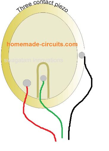
The above three contact piezo may also be used in two wire transducer application where the third central feedback contact is not used.
The external frequency from a piezo driver is applied across the metal base and the inner piezo material, the piezo then starts vibrating at the applied frequency level, generating a high pitched sound.
However this sound can be very insignificant and low in volume unless the piezo is fixed over a special plastic housing with a center hole.
The size of the hole matters and should not be more than 8mm in diameter or less than 6mm in diameter.
The plastic housing should be such that the piezo is stuck with a adhesive over a raise platform just a couple of mm above the base of the housing which consists of the above explained hole.
The raised portion should be just 2 mm wide, barely supporting the circumference edge of the piezo.
The whole sticking (installation) procedure has been explained in this simple buzzer circuit article.
Technical Specs - How Piezo Operates
As we know that a piezoelectric transducer converts a mechanical force into equivalent electrical pulses across its body terminals. The application of this mechanical force on the piezo material could be in the following 3 basic forms:
- Transverse
- Longitudinal
- Shear.
Transverse effect
In this impact pressure is cuts along a neutral axis (y) moving charges along the (x) direction, perpendicular to the line of force. The magnitude or the level of charge (Cz) produced depnds on the geometrical specifications of the piezo electric material. If we take a, b, d as the dimensions we get:
Cz = dxyFyb/a
where a is the dimension across the neutral axis, b lies on the line which generates the charge, and d is relevant piezolectric coefficient.
Longitudinal effect
In this impact the magnitude of charge transferred is specifically equivalent to the force applied. However this is not dependent on the piezoelectric dimensions.
The only way to increase the charge output from a piezoelectric element is to configure many of these device mechanically in series or piled up one above the other, but electrically connected in parallel. The generated charge can be calculated using the following formula:
Cx = dxxFxn
Where dxx denotes the piezoelectric coefficient for a charge across the x-direction, produced by the stress or the force applied across the same direction. Fx represents the force applied in the x-direction, while n represents the number of piezo elements stacked up one above the other.
Shear Effect
In this impact the generated charges are specifically equivalent to the exerted force, but not depending on the piezo dimensions. When n number of transducers are stacked up in series one above the other, and electrically connected in parallel, the magnitude of charge can be calculated using the following equation:
Cx = 2dxxFxn
Only the transverse effect features an adjustable sensitivity for the applied force on the piezo material, which is not available for the longitudinal and shear effect results.

Questions & Answers
Hi – What is the best waveform to drive a piezo transducer. Square or Sine wave?
I have always thought sinewave as square would have too many harmonics? Any thoughts.
And what sort of power is required to drive 2 small 50mm diameter 20khz and 25khz piezo transducer. How many watts? to make sound at 20m
Hey Gray, Yep…Sine wave is always the best waveform for driving a piezo transducer.Piezo is a resonant device so sine wave excites only one frequency and gives clean vibration with less heating and less stress.
Square wave is used sometimes only because it is cheap and easy, not because it is best.
About power, piezo is voltage driven, not power driven like a speaker. A 50 mm ultrasonic piezo normally needs high voltage around 30 Vpp to 150 Vpp but current is very small. Actual electrical power is usually below 1 watt, often only few hundred milliwatts.
At 20 kHz or 25 kHz, sound does not travel far in air and many of people cannot hear it. Getting audible sound at 20 meters is not realistic at these frequencies.
I have learnt more in those 4 paragraphs than trying to get out of the transducer manufacturers in China.
I am using 2 x ICL8038 waveform generators, each set to 20khz and 25khz sinewave, and with a long period timer, switching between the 2. I have the easy option of going to a square waveform or a triangle waveform.
The outputs then go to OPA454AIDDAR, which is a low-cost operational amplifier with high voltage (100 V) and relatively high current drive (50 mA).
ICL8038 and OPA454 both have +15v 0v -15v power supply to give 30v peak-to-peak. This gives the option of increasing the peak-to-peak supply voltage later, if need be, up to the ICL8038 max of 36v peak-to-peak.
My only thoughts are, how do I measure the output of the ultrasonic transducers ? As I will not be able to hear them.
Thanks, and yes you are right, you can hear those frequencies…. basically you need special high-frequency sensors or oscilloscope capable of ultrasonic to “see” the output. Regular ears cannot detect it.
If you want I can give you a simple cheap way to check ultrasonic output using just a small piezo and scope
I am interested to hear about your “simple cheap way to check ultrasonic output using just a small piezo and scope”.
Sure, you can do t in this way:
Take a small piezo disc (passive type 27 mm transducer), next connect one piezo wire to the scope ground clip and the other wire to the scope probe tip. No power supply, nothing else needed.
Keep this piezo disc very close to the ultrasonic transducer in air. When the ultrasonic driver is ON, then sound vibrations hit the piezo and it generates a small AC voltage.
Set the scope to AC coupling, around 10–100 mV/div and time base suitable for the frequency, for example 5–10 us/div for 40 kHz. You will see a waveform if ultrasonic output is present.
Optionally a 100k resistor across the piezo can be added for stability.
Hey S-Man!,
Remedy here. Is it possible to use three piezo transducer in a triangulation setup to provide 360 degree sensitivity to a round hoop while the output to a sound module “used for triggering drums” only see’s them as one unified sensor? To simplify. I need multiple sensors for consistent detection of vibration on a large apparatus but need them to react as a singular output source to avoid secondary detection from one strike.
Hey Riley, I think that maybe possible, by hooking up 3 piezos in parallel.
I will test and post results. Thanks
Very good info.
I have a question. I would like to make rodent repeller circuit generating a variable frequency from 20-40 khz. Will a piezo transducer work? If not can you point we to a speaker that will
Regards
Ken
Thank you, yes this piezo should work when enclosed appropriately.