ELF stands for Extremely Low Frequency, which is an electromagnetic radiation generated by most of out household electrical equipment.
Regarding the effect and severity of ELF fields on human health, debate remains heated. However, I believe there is enough data for us enthusiasts to adopt a conservative stance on the level of exposure we must permit us, particularly because we work with electronics on a regular basis.
Long-term exposure should be kept to one milligauss or less, in my opinion. Of course, without a milligauss meter, it might be challenging to determine your ELF level of exposure.
This is where the ELF Monitor discussed in this post comes into play.
It determines if the amount of radiation is harmless or not by detecting the 50 or 60-Hz electro-magnetic field emanating from any equipment.
The circuit's hazard trip point ranges from 1.5 to 2.5 milligauss.
You may locate potentially harmful ELF fields and their origins. This is done using the circuit to scan the area surrounding your house, office, or work environment so you can take the necessary actions.
How the Circuit Works
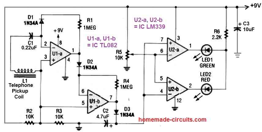
Referring to the above circuit diagram, the sensor L1 is the most important part of the ELF Monitor circuit. The sensor—a telephone pickup coil often used to capture phone calls—detects any magnetic field with a 60 Hz frequency and generates a voltage inversely proportional to its intensity.
Even while the inexpensive sensor lacks the sensitivity of more costly ones, it is adequate to create a straightforward, low-cost ELF monitor that can determine whether something is safe or not.
An opamp with two biFETs is used in the circuit. The first stage's feedback loop uses a germanium diode (D1) to give nonlinear feedback.
The diode enables the operational amplifier (op-amp) to amplify and rectify tiny signals from the sensor. As long as the op amp's output voltage is inadequate to push the diode into conduction, the feedback loop remains shut and the op-amp runs at maximum voltage gain.
However at this point, a little voltage from the ELF sensor is all that is needed to generate a huge output.
The huge output now turns on the diode, allowing the resistor R1 to establish the gain of the amplifier.
To be precise, the half-wave rectifying op amp amplifier U1a is used to process the sensor's millivolt-level AC signal. In the process diode D1 compensates the voltage drop across diode D2.
The signal is then further amplified by the adjoining op-amp U1b so that it is powerful enough to operate the couple of LM339 comparators ICs. These ICs serve as the display drivers.
Due to their greater performance and smaller voltage drop (approximately 0.3 volts), germanium diodes were selected for D1–D3. It is possible to calibrate this ELF monitor circuit nicely, thanks to the potentiometer (R5). Capacitor C1 ensures that no potential DC from resistor R2 gets across, via the coil.
Construction Tips
A few architectural suggestions for the ELF Monitor circuit are worthwhile to highlight. To house the circuit, you should start by using a non-conductive plastic casing.
A metal casing will prevent accurate measurements. A tiny portion of strip board could be used to mount and solder components. To reduce stray pickup in the wiring, keep all connection lengths as small as you can.
After you've finished the main circuit, you'll need to connect it to the pickup sensor coil. Some insulated wire could be protruding from the coil's edge.
Remove this wire, leaving the coil with roughly 3 inches of it still connected. Split and peel the cable's wires. Glue or epoxy can be used to secure the pick-up coil to the front of a plastic enclosure.
To make room for the two LEDs and the power switch, the enclosure's upper surface must be punched with appropriate holes. Likewise, you will need to plan an appropriate mounting system for the battery.
How to Test
Testing must be performed in a location with minimal exposure to 60 Hz emission. Switch on the ELF monitor circuit, then tweak R5 so that the red LED is approximately about to come on and the green LED is just about to go off. Now the circuit is set and perfectly ready to test or sense an ELF and indicate through LEDs.
When an ELF field is present, the circuit responds very rapidly; however, when the field is gone, there is normally a delay of around one second.
To check the device, switch on a television and gently advance the detector towards the screen from a distance of about 2 feet.
When you get sufficiently closer, the red LED will illuminate and the green LED will shut off. You'll probably discover that you may reduce your ELF exposure by rearranging as you go about inspecting various gadgets.
For instance, when I discovered that one of my PCs had an external power supply that produced significant ELF radiation, I actually moved the power supply to a place that was more discreet and farther away from my workplace.
Your exposure can be further decreased by doing other straightforward things like switching from a fluorescent desk lamp to an LED bulb.
When moved into or out of a static magnetic field, the ELF monitor can also detect the presence of the field. The green LED will turn back on if the monitor is left fixed in the magnetic field for a brief period of time.


Need Help? Please Leave a Comment! We value your input—Kindly keep it relevant to the above topic!