In this post we systematically discuss how to connect diodes in parallel for getting upgrading the overall current specifications of the assembly. This requires special circuit arrangement to ensure uniform current distribution between the devices.
Whenever an inductor based load is involved in a DC circuit, incorporating a back EMF protection diode or a freewheeling diode becomes imperative in order to protect the BJT or the mosfet responsible for driving it.
How to Calculate Parallel Diode
However calculating and connecting diodes in parallel is never an easy task to implement.
We all know that just like capacitors inductors have the property of storing and reverting electrical energy across itself.
The storing of the electrical energy takes place when the inductor is subjected to a potential difference across its leads while the throwing back or discharging the stored electrical energy happens the moment this potential difference is removed.
The above explained "kicking back" of the stored energy across an inductor or a coil is termed as "back EMF"and since the polarity of the "back emfs" is always opposite to the applied potential difference becomes a serious threat to the device employed for controlling or driving the inductor.
High Current Diodes for Back EMF Protection
The threat lies in the fact that the reverse voltage inflicted by the inductor tries to make its way through the associated power device such as a BJT with a reverse polarity causing a instant damage to the device.
A simple idea to counter this issue is to add a rectifier diode directly across the coil or the inductor, where the cathode connects with the positive side of the coil while the anode towards the negative.
Such diode arrangement across DC coils is also called freewheeling or a flyback diode.
Now whenever the potential across the coil is removed, the generated back emfs swiftly finds its path through the diode and gets neutralized instead of forcing through the driver device.
A classic example of this phenomenon may be witnessed in a BJT driven relay driver stage, you might have come across plenty of these in numerous different circuits. A diode could be normally seen connected across such relay drivers stages, which is done for protecting the BJT from the lethal back emfs kicked from the relay coil every time it's switched OFF by the BJT.
Flyback High Current Diode Schematic
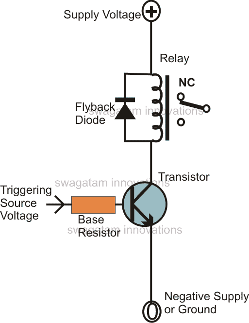
A relay being a relatively small load (high resistance coil), normally a 1 amp rated 1N4007 diode becomes more than sufficient for such applications, however in cases where the load is relatively huge or the coil resistance is very low, the generated back emfs could be equivalent to the applied current levels, meaning if the applied current is in the range of 10 amp, the reverse emf would also be around this level.
To absorb such massive jolts the reverse back emf, the diode too must be robust with its amp specs.
Normally, in such cases where the back emf could be above 10 or 20 amps, finding a suitable single diode becomes difficult or too expensive.
A good way to counter this is to connect many smaller rated diodes in parallel, however since diodes just like BJTs are semiconductor devices, don't go well when connected in parallel.
The reason being, each diode connected in the parallel string could have a slightly different switch ON levels making the devices conduct separately and the one which switches ON first becomes responsible of taking on the greatest bulk of the induced current, which itself makes the particular diode vulnerable.
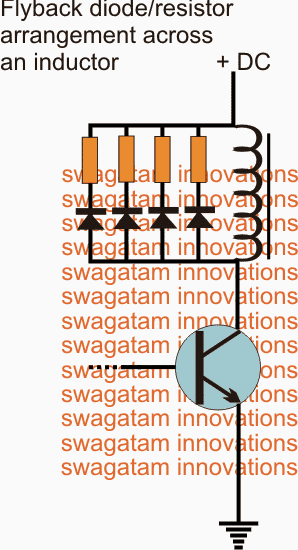
Therefore, in order to solve the above concern each diode must be added with a series resistor, appropriately calculated for the freewheeling application as per the given parameters.
Connecting Diodes in Parallel
The procedure of connecting diodes in parallel correctly may be done in the following manner:
Suppose the maximum assumed emf current across the inductor is 20 amps, and we prefer to use four 6 amp diodes as the freewheeling diodes across this coil, implies that each diode should share around 5 amp current, the same applies for the resistors also, which may be connected in series with them.
Using Ohm's law we can calculate the resistors such that they generate minimum safe resistance together but singly offers an optimal high resistance forcing the current to share the paths equally across all the diodes.
Generally a 0.5 ohm resistance will be quite safe for safeguarding the power device, therefore 0.5 x 4 becomes 2 ohms, so each diode could be 2 ohms rated.
The wattage together must be rated for handling the entire 20 amps, therefore dividing 20 by 4 gives 5, meaning each resistor must be rated at 5 watts each.
Using Resistors in Series with Diodes to Prevent Thermal Runaway

Questions & Answers
Swagatam Sir 🙏
Back EMF ko reduce karne ke liye 4 parallel diodes ke sath kya 4 resistor ki jagah sirf ek 20 wattage ki resistor ko series mein connect kar sakte hain ?
Hi Dev,
Sorry No, a single common resistor will not work with the 4 diodes….you will have to use 4 separate resistors as shown in the diagram.
Hi, I have an issue with an older preamplifier which might be because of the freewheeling diode being insufficient or it might not. I’m not an electrician. The preamp has an output relay 24dc and as this is eiter switched on or off it will induce a relative large pop sound in any amplifier. It has a MW11 (zener) as a freewheeling diode or at least connected as one. the voltage trough the relay goes from 0.1V-10V at max output. The diode is pretty far away from the relay – on another pcb (EQ pcb and the relay is on the flatamp pcb), hence to my question, could I mitigate the pops with a 1N4007 diode connected in parallel with the zener but closer to the coil of the relay or would that be harmful in any way?
Thank you for the excellent info on the page btw
Best regards
Mikael
Hi, the freewheeling diode has nothing to do with pop sound. It is actually due to the charging and discharging of the amplifier’s output series capacitor. You will need to modify the relay circuit to prevent this thing from happening.
More info has been provided in the following article:
https://www.homemade-circuits.com/loudspeaker-thump-sound-eliminator-circuit/
Hi, Thank you for the quick reply!
Ok. But I with all the power amplifiers which i have connected to this preamp the same pop comes out from the output relay of the preamp. After the relay there is nothing but the wiring connected directly to the outputs. No caps. It is a dc-coupled pre-amp. It does have a muting circuit much like the one in your article though. Still I’m not sure about how to go about with that pop in this kind of preamp.
Best regards
Mikael
The capacitor may be between the amplifier output and the loudspeaker.
You may have to open the preamplifier unit and modify the relay section as described in the linked article.
Dear Swagatham
I am in need of Ultra Fast diodes (UF4001 to UF4007) to use with relays and dc motors as flyback diodes to protect the driver transistor from BACK EMF. But I don’t have them stock.
( I know, 1N4001 to 1N4007 can be used, but they are slow compared to UF4xxx series.)
I have a lot of BA159 and FR107 diodes. Which one among these can be used instead of UF4xxx series diodes. Are they faster &safer than UF4xxx diodes while handling BACK EMF….?
Thanks in advance.
Dear Anil, UF4xxx are much faster than the oter two alternatives…however does your application require faster than 500 nanosecond recovery time…If not then you can easily use BA159 or FR107
Can we use a zener diode for this purpose. If yes, Please propose a circuit.
zener diode is not recommended here since rectifier diodes are more powerful, and cheap compared to zeners.