In this post I have explained a 6 very useful yet simple ultrasonic transmitter and receiver circuit projects which can used for many crucial applications, such as ultrasonic remote control, burglar alarms, electronic door locks, and for listening to frequencies in the ultrasonic range which are normally inaudible to human ears.
Introduction
Many commercial ultrasonic gadgets work with a predetermined frequency and make use of transducers which are made to peak, or resonate, at the specific frequency. The restricted bandwidth and price of the majority of of such transducers cause them to become inappropriate for hobby and DIY implementations.
But in fact, that isn't an issue, since virtually any piezo speaker could be applied like a ultrasonic transducer for both, in the form of a transmitter output device and also as receiver sensor.
Although piezo speakers efficiency cannot be compared with the efficiency of a specialized, industrial transducer, as a hobby and fun project these can work perfectly. The device we employed with the below explained circuits was a 33/4 -inch piezo tweeter which is available from most online stores.
1) Simplest Ultrasonic Generator
generator may be constructed without much difficulty
and very quickly.
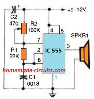
Our very first circuit, is shown in the above Fig, is an ultrasonic generator which uses the well-known 555 IC timer in a adjustable frequency astable multivibrator circuit. The design outputs a square wave signal which, works with R2, for tuning through around a frequency range of 12 kHz to over 50 kHz.
This frequency range can easily be adjusted by altering the value of capacitor C1; employing a lower value will cause the range to go higher, while larger value will make the range that much smaller.
2) Ultrasonic Generator with Fixed 50% Duty Cycle
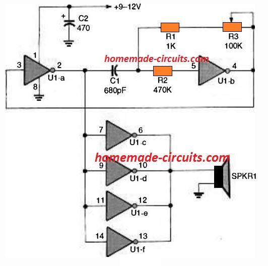
The next ultrasonic generator, revealed in the above Fig. 2, makes use of 6 buffer gates of a solitary 4049 CMOS inverting buffer IC.
A couple of the buffers, U1a and U1b, can be seen attached within a variable-frequency astable-oscillator circuit having a 50 % duty cycle, square wave output.
The rest of the 4 buffers all connected in parallel in order to enhance the output over the connected piezo element. This much better ultrasonic generator's frequency range is approximately similar to the previous IC 555 version. However, The major advantage of this design is its accurate 50% duty cycle around the full frequency range.
That said, the frequency range could be made higher by lowering the capacitor C1 value, and the frequency can be decreased by using higher values for C1. The 100k potentiometer, along with resistor R3, fixes the output frequency.
3) PLL Ultrasonic Generator
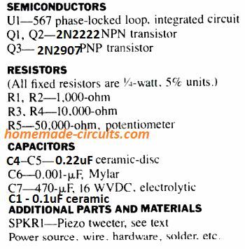
The LM567 phase-locked-loop (PLL) IC is used for generating ultrasonic frequency in our 3rd concept as proven in the above figure 3. This circuit provides a number of features better than previous two ultrasonic concepts.
First, the IC 567's in-built oscillator is developed to work within a incredibly large frequency spectrum, from under 1 Hz and as high as 500 kHz. The generator's output waveform, at pin 5, exhibits outstanding symmetry all through its performance range.
The generator additionally gives a increased output compared to other two circuits for the reason that output is matched much closely to the piezo tweeter's (SPKR1) impedance.
The output of the circuit could be tweaked through around 10 kHz to more than 100 kHz working with potentiometer R5. Transistor Q1 is hooked up like a common collector circuit in order to keep the 567's output aloof as well as to drive the output-amplifier circuit which is created using the transistors Q2 and Q3. The circuit could be changed into an ultrasonic cw transmitter by breaking the IC's pin 7 connection and inserting a switch key in series.
In that case, you will require some form of ultrasonic receiver to hear the signals; and that is the exactly what we are going to discuss in our next circuit.
4) Ultrasonic Receiver Circuits
explained LM 567 ultrasonic transmitter for best results.
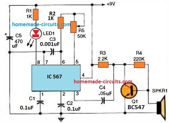
A ultrasonic receiver circuit using a 567 PLL IC that features a frequency tuning capability is shown in the above diagram. The IC's tunable oscillator circuit is identical to the earlier generator circuit, and handles exactly the same range of frequency. An LED is positioned at the pin 8 detector pin of the IC which quickly indicates the detected signals.
Transistor Q1 is positioned to amplify the minute ultrasonic signals detected by the piezo device and forwards them onto the PLL.
How to Test
To test the ultrasonic working, switch on the IC 567 ultrasonic generator circuit and move the transmitter piezo all through the area. Beginning with the minimum setting, fine-tune R5 bit by bit until you are unable to listen to anything from the speaker. This should fix the circuit's output frequency approximately to 16 and 20 kHz, depending in your ear's sensitivity to high-frequency.
Now, switch on the ultrasonic receiver circuit and position its piezo transducer at approximately 12 inches away from the generator's speaker, although having itaimed in the exact same direction. Adjust the receiver through R5, beginning from the minimum frequency point (which corresponds to the pot's maximum resistance range), and little by little maximize the frequency until yo see the receiver's LED just illuminating.
If you see receiver not responding to the transmitter output signals, try aiming the receiver's piezo accurately the generator's speaker and keep doing this persistently. As soon as the receiver detects the signal and the LED lights up, move the two Tx/Rx piezo away by a a minimum of ten feet and begin fine tuning yet again.
Once you find all is performing satisfactorily, you can make use of the the transmitter's attached telegraph key (optional at pin7) and check out the LED response on the receiver.
The LED must respond to this by flashing in the the dot-and-dash style as tapped by you using the telegraph key. An additional application of this ultrasonic generator/ receiver set can be in the form of a straightforward burglar alarm sensor.
Attach a 5 V relay across pin 8 of the receiver's LM567 and the battery's positive pole. Arrange the Tx and the Rx piezo devices approximately a foot apart and focused within the same path, but clear of any nearby object.
If a person goes in close proximity to and in front side of the a pair of speakers the ultrasonic frequency will be reflected back triggering the receiver's relay to switch ON. The output contacts of the relay could be applied to switch on an alarm or a siren device.
5) Highly Sensitive Ultrasonic Receiver Circuit
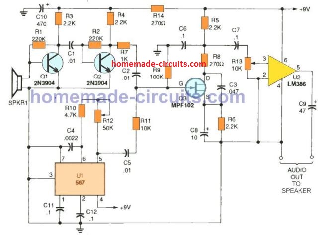
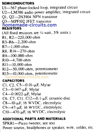
The last ultrasonic receiver circuit design is actually an extremely sensitive ultrasonic receiver which can easily pick up almost anything within the ultrasonic frequency range. You possibly can listen to insects, bats communications, engines, etc.; the idea could also be used in conjunction with the above explained ultrasonic generators for developing high quality ultrasonic systems.
The design, works using the principle of direct conversion. Transistors Q1 and Q2 boost the ultrasonic signals detected by the piezo speaker. The Q2's collector output is then used to drive the JFET (Q3) input, which can be seen hooked up like a product-detector circuit.
The PLL (U1) stage in this concept is employed like a tunable heterodyne oscillator which additionally feeds the input of the JFET detector circuit. The inbound ultrasonic signal combines with the frequency of the heterodyne-oscillator generating a sum and difference frequency.
The high frequency element is filtered out through the C3, R8, and C6 component network. The leftover low frequency output is allowed to enter across the LM386 audio amplifier input. A speaker or headphones could be attached to the circuit's audio output.
6) Another Ultrasonic Receiver Circuit for listening to Sounds above 20 kHz range
Also Recommended for you: How to listen to ultrasonic sounds
The frequency detection range of the our ear is hardly up to 13 kHz frequency. The function of the ultrasound detector is to defeat this limitation by switching the frequency of high frequency noises for example dog whistles, barely audible gas leaks, bat bleeping, and several artificial ultrasonic sounds for example lightly tapping on a newspaper.
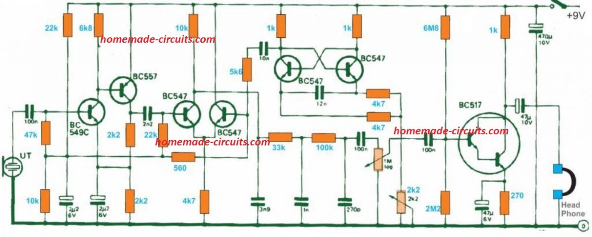
The 'ultrasound' detected by the input transducer is boosted and fed to a product detector. An astable multivibrator is included since the BFO stability may be not be of much significance. In addition for the required signal differential, the circuit additionally generates the BFO signal on its own as well as the summing frequency, which is then terminated inside a low pass filter fixed at 4 kHz.
The signal resulting here is yet again amplified to operate a set of headphones. The circuit works with around 8 milliamps, therefore it can easily be powered from a 9 V dry battery.


Questions & Answers
Hi Swagatam, Priyanka here
I wanted to try the circuit in simulation first, can you recommend what software to use?
Hi Priyanka, sure, you can simulate it in the following link, or directly use the falstad.com website…
https://www.homemade-circuits.com/circuit-simulator/
Or if you want I can do it for you…
oh okay! thankyou for sharing!!
I’ll let you know after i try
thankyou so much:)
OK great!! let me know if you have any problems…
Hi Swagatam, I have finished the circuit in simulator and i am getting high pitched and low pitched beeps as output.
can you kindly check if it is indeed producing the intended output?
https://is.gd/TSjTId
thankyou again for helping me out.
Thank you Priyanka,
Yes, it is working, but because the frequency is too fast the switching difference is not visible on the scope, so I increased the capacitor value to 100nF and then the 2X multiplying effect was clearly visible….you can also import the following simulation in your falstad website and check the results:
$ 1 0.000005 4.818269829109882 56 5 50 5e-11
165 240 128 256 128 4 4.999999950000001
R 304 96 304 80 0 0 40 5 0 0 0.5
O 368 192 416 192 0 0
w 240 160 208 160 0
r 208 160 208 96 0 45000
w 208 96 304 96 0
w 208 256 240 256 0
c 208 256 208 304 4 1.0000000000000001e-7 3.2435533214048893 0.001 0
g 208 304 208 320 0 0
w 208 224 208 256 0
w 208 224 240 224 0
r 208 160 208 224 0 10000
w 304 96 368 96 0
w 368 96 368 160 0
g 336 288 336 304 0 0
c 304 288 304 336 4 1e-8 3.333333333333333 0.001 0
g 304 336 304 352 0 0
w 208 96 144 96 0
t 96 112 144 112 0 -1 -0.5699333709475534 -0.589681908178548 100 default
r 208 160 144 160 0 18000
w 144 128 144 160 0
r 96 112 96 64 0 10000
w 96 64 208 64 0
w 208 64 208 96 0
r 96 112 32 112 0 10000
t -48 160 32 160 0 1 0.5735449196789845 0.602187864808709 100 default
w 32 112 32 144 0
g 32 176 32 256 0 0
r -48 160 -96 160 0 10000
R -96 160 -96 96 0 0 40 5 0 0 0.5
w -48 160 -48 192 0
s -48 192 -48 240 0 1 false
g -48 240 -48 256 0 0
o 2 32 0 4098 5 0.1 0 1
oh okay, thankyou so much for helping out!
Will do the changes
Prefect! let me know if you face any further issues with the circuit…
Hi Swagatam, Hope u remember me
The thing is that i will be using this circuit as my final year project, which is basically for rodent deterring. While this remains the pivotal part of the project, i.e day and night frequency variation, I just need one more feature that I can add to this project to increase its functionality.
Kindly guide me through this
Thankyou so much swagatam!! i’m really grateful for your help, i wouldn’t have finished my project if it weren’t for you!
You are welcome Priyanka, I am glad it helped you to complete your project. Please keep up the good work, and feel free to contact me if you have any further doubts or issues with the circuit…
hey swagatam!!, the circuit works thankyou so much
i just have one more doubt, i have an idea of how this circuit works but i have to explain it to my faculty so i have to be accurate with the working and the terminologies, so can you just give me a brief rundown of the circuit and explain what does what?
Thanks Priyanka, that sounds great! Glad it is working as intended!
Here’s a brief explanation for the proposed circuit design:
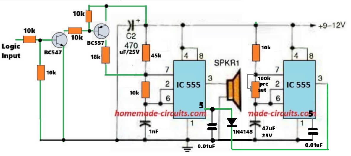
The circuit uses two IC 555 timers. The left IC 555 is configured as an ultrasonic frequency generator that drives the speaker. The right IC 555 operates as a low-frequency modulator. Its output is applied to pin 5 (control voltage) of the left IC 555 causing the ultrasonic frequency to continuously vary instead of remaining fixed.
This frequency modulation produces a sweeping ultrasonic sound which is more effective for repelling rodents.
Additionally the BC547 and BC557 transistor stage allows an external logic input to shift the operating frequency range. When the input is high, then left 555 circuit increases the ultrasonic frequency on the speaker, and when low, it operates at its default lower frequency range.
The 1N4148 diode ensures proper isolation between the two oscillator stages and maintains stable modulation behavior.
Swagatam, is there any possible way to continue with the previous circuit while incorporating the intermittent pulsing feature?
Hi Priyanka, sure, here’s the modified design you can try :
Hi Priyanka, Yes, I remember you and your previous requirement very well.

If you are trying to build a rodent deterrent circuit then I would recommend you the following circuit, because the frequency needs to be intermittent and not continuous, which becomes more effective as a deterrent.
The LM358 section is not important, you can remove it and connect the transducer directly between the pin3 and ground.
Please let me know if you have any related questions…
Hi Swagatam,
I’m looking for some guidance here, i want to proceed with the 1st circuit for ultrasonic frequency generation.
the basic idea is to generate 2 frequencies (22khz and 44khz) and switch them based on the digital output from ldr module ie. 0 should produce 22khz and 1 should produce 44khz. kindly suggest some approaches that I can take to achieve this
this is for my project and I would really appreciate your valuble insight
Thankyou!!
Thank you Priyanka,
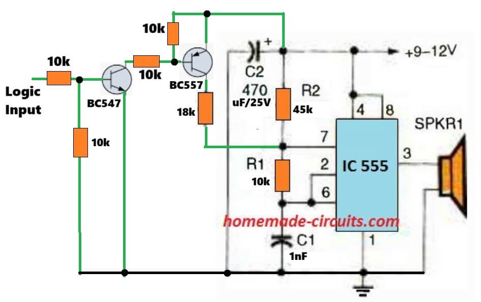
Please try the following design and let me know how it works:
Thank you so much, will try and let you know!!
Sure! you are welcome!!
I have limited circuitry knowledge. In the 1980’s as a hobbyist, I built some circuit boards.
My need, (and the humor). 68yrs age, need to supplement my income. Started cricket “farm” to bring in a few hundred a month. Its VERY important to hear when they are chirping.
I didn’t know I can’t hear 6khz, (the approximate hz they chirp at).
I need to build a circuit that will recognize the 6hz chirp only, and light a led light according to the cadence it hears. Can you help me please?
Thank You. I appreciate you doing this. I will be sure to let you know my results, I expect to be able to commit to it after Christmas. Till then my wife has agreed to continue to be my ears.
By the way, she’s very appreciative of you too 😉
Thank you so much Hank, Let me know if you have any issues with the circuit.
And please convey my regards to your wife.
All the best to you!
Hope your holidays were well. I’m about to assemble cricket chirp circuit. Few questions. 1) 9v ground I didn’t see. I see the “simple hum filter” schematic is similar, shows ground at the 33k cap. Good choice for my cricket chirper? 2) audio input, what is required/suggested? 3) I didn’t understand notch filter calculator formula, I have no formal education. Don’t understand the “tt” in formula. I typed random values into in the calc. I came up with R4 2k ohms, C4 13nf gave me 6121hz
R4 1.95k ohms and C4 13nf = 6278 hz.
Hi, here are the answers:
The ground is nothing but the negative DC supply line from the battery.
The audio input is the 6kHz amplified sound input socket..you will have to first amplify the 6kHz sound and use the notch filter to detect and indicate it.
There’s no need to understand the formula, you can use the calculator to get the cut-off values…yes those values which you got, you can try them…
I think we might have to use a notch filter circuit for this application.

You can try the following circuit, with some accurate adjustments to achieve the 6kHz cut-off
To adjust the parts please follow the instructions as given in the following two articles:
https://www.homemade-circuits.com/simple-hum-filter-circuit-for-amplifiers/
https://www.homemade-circuits.com/notch-filter-calculator-tool/
Swagatam
RE: Highly Sensitive Ultrasonic Receiver Circuit
r09-19-2024
Hi, there.
I see that the circuit diagram includes a total of one piezo speaker tweeter, but curious about what is the maximum number of receiving [RX] ultrasonic sensors (piezo speaker tweeters) that can be included in the project “Highly Sensitive Ultrasonic Receiver Circuit”?
Thanks.
Glad you’re asking R.L. That could be helpful in my project
Thank you R.L.,
The maximum number of output speakers will depend on the wattage of the speakers. The LM386 can provide an output power of 1 watt, so you can probably dimension the total power for the multiple output devices up to 1 watt range, or if you want to add more speakers exceeding 1 watt then you may consider replacing the LM386 amp with a more powerful one.
Hello Swagatam, I want to make circuit 4 for a project. But, I am facing the issue of not finding the Ic i.e LM567. Can you suggest any alternatives for the IC. Also,can you give the relation between frequency and the variable resistance. Thank You.
Hi Vatsal,
The LM567 is the main component of the circuit and it is specifically required for implementing the results, unfortunately it cannot be replaced by any other IC.
In that circuit R5 decides the detection frequency of the circuit.
If you do not want to use the LM567 then you can try the last circuit in the article.
Hello Again Swagatam,
I tried the circuit 1 with the formula you suggest earlier. When I turn on the the circuit, the buzzer starts buzzing even though the circuit is set to emit sound of 25 KHz. I am not able to find the exact problem.
Hello Vatsal,
Can you please provide the values that you have selected for R1, R2, and C1.
I will confirm whether or not the parts are correctly set for getting the 25kHz frequency.
As per the first diagram R1 is the lower resistor and R2 is the upper resistor.
Please let me know.
I’ve used 22K resistor as R1 and 13.6K resistor as R2, and 0.001 micro F as C1
Assuming 22k is the lower resistor and 13.6k the top resistor, your components are correctly set and will produce 25kHz at the output.
Please connect a 0.1uF capacitor between pin#5 and ground and check if that helps to keep the buzzer quite?
Hello again Swagatam,
Due to your advice, I managed to mitigate the noise coming through the speaker. My current issue involves the frequency that is being read by the transducer. My partner’s ultrasonic transmitter is sending a signal of 15 kHz. When hooking up probes to different parts of circuit #5 I am getting a range of frequencies at SPKR1 ranging from 15 kHz – 35 MHz that are swapping constantly. When putting the probe at R12 I can tune it to the exact 15 kHz range provided by the transmitter however the noise from the transducer still occurs. I have also noticed that there is a high-pitched noise coming from the transmitter transducer but not from the receiver transducer. I’ve thought about connecting a low pass filter between the SPKR1 port and the transducer to see if those higher frequencies can be blocked but I was wondering if you have any suggestions on my current situations. Ideally I could send you images of our oscilloscope findings but please ask any questions if you have any confusions.
Thank you,
Jacob Ralls
Thank you Jacob,
I don’t think the 35MHz reading on the meter is real, it could be a false reading or maybe the meter is getting upset due to high frequency and showing faulty readings.
Could you increase the transmitter and the receiver frequencies above 15kHz and check the response. That would confirm whether the noise is due to the 15kHz or something else.
Also, i think an oscilloscope testing would provide more accurate readings.
Actually, I have not yet checked this circuit myself so providing perfect suggestions seems difficult for me.
A question I have is that if you have not checked this circuit yourself through hardware, was there a simulation software you utilized to test if it worked through simulation? If so could you elaborate on what kind of software you used or what your methodology was when designing the circuit?
Thank you very much for your time, I can’t emphasize enough how much of a help you have been.
Thank you Jacob, Actually the above circuits were not designed me, they were contributed by an external author. From the print it seems they were acquired from an old electronics magazine.
Unfortunately, my partner’s transmitter only seems to work at roughly 15 kHz. We have been doing our testing thus far through the use of an oscilloscope and when attempting to match his frequency there is a slight amount of static noise through the speaker but not as severe as before. I assumed that because the receiver is very sensitive it would make sense that the transducer is receiving all sorts of frequencies with varying ranges. I’ll keep testing it and maybe try a different piezo transducer if need be.
Thanks Jacob, for updating the results. I appreciate it very much.
Yes, that makes sense.
Hello Swagatam, I am wanting to try the very basic circuit i.e circuit 1. Can you give me the relation of frequency to the variable resistor R2.
Hello Vatsal,
You can use the following formula to calculate the frequency. You can replace the 100k pot with a fixed resistor through this calculation:
F = 1.44/[(R1+R2*2)*C1]
Please note that R1 and R2 are written oppositely in the diagram, which is wrong. Meaning the 100k pot is actually R1 as per the formula, and the resistor connected with C1 is R2. So please substitute the values accordingly in the formula.
Also, if you want to use the 100k pot, please add a 10k resistor in series with the pot, otherwise the IC may burn if the pot is rotated fully towards the positive line.
Hello Swagatam. I built the 3rd circuit and I am now undergoing testing. When I power the circuit (without the piezo transducer) I get a constant buzzing noise coming out of the speaker. When adjusting the R13 pot, the volume gets adjusted but it is also changing the pitch of the output as well. To my knowledge this is only to adjust the volume. I was wondering if you knew any outputs that the speaker may have with no transducer attachments or if you are knowledgeable of how the properly test this circuit.
Thank you very much.
Thank you Jacob,
I guess you are referring to the 5th circuit.
The buzzing sound could b due to the frequency generated by the LM567 circuit.
However R13 is definitely a volume control and it should not cause any change in the tone of the buzzing. Because the R13 is highly buffered through C7, C6, R9 which cannot impact the LM567 operation.
You can try two things, disconnect the gate of the FET from the junction of R11, C2 and check whether the buzzing sound still persists or not.
Or, you can ground the Q1 base and check whether the buzzing sound stops or not.
You can also tweak the R12 and check the response from the speaker.
Hello again Swagatam! In circuit #3 is it possible to connect a microphone as an input to generate a signal that can transmitted to the ultrasonic frequency range?
Thank you again for your help.
Hi Jacob, sorry, a microphone cannot be used for transmitting frequencies at ultrasonic range.
A piezo transducer is the most suitable device for this.