In this post I have explained how to build and optimize 5 useful IC 555 oscillator circuits, whose waveforms can be further enhanced for generating complex sound effects.
Overview
The basic mode that is normally employed for making IC 555 oscillators is the astable circuit mode.
If we look at the astable circuit shown below, we find the pinouts joined in the following manner:
- Trigger pin 2 shorted to Threshold pin 6.
- A resistor R2 connected between pin 2 and the discharge pin 7.
In this mode, when power is applied, the capacitor C1 exponentially charges via resistors R1 and R2. When the charge level climbs up to 2/3rd level of the supply voltage, causes the discharge pin 7 to go low. Due to this, C1 now begins discharging exponentially, and when the discharge level falls down to 1/3rd supply level, sends a trigger at pin 2.
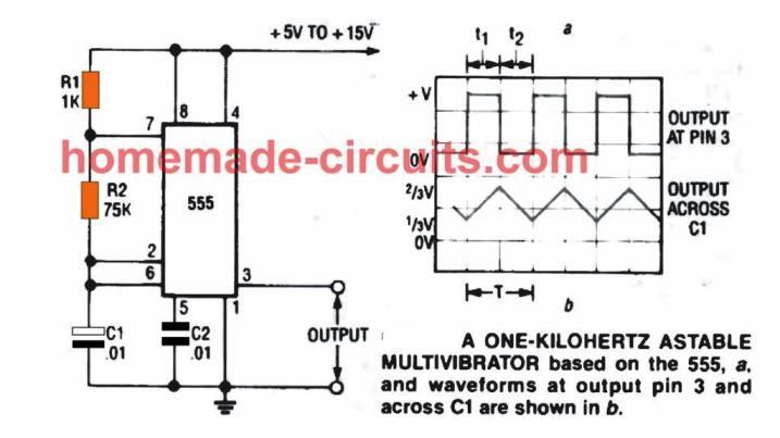
When this happens pin 7 again turns high initiating the charging action on the capacitor until it teaches the 2/3rd supply level. The cycle continues infinitely establishing the astable mode of the circuit.
The above working of the astable results in two types of oscillations to occur across C1 and across the output pin 3 of the IC. Across C1, the exponential rise and fall of voltage creates a sawtooth frequency to appear.
The internal flip flop responds to these sawtooth frequency and converts then into rectangular waves at the output pin 3 of the IC. This provides us with the required rectangular wave oscillations at the output of the IC pin 3.
Since the oscillation frequency entirely depends on R1, R2, and C1, the user is able to alter the values of these components to get any desired values for the ON OFF periods of the oscillation frequencies, which is also called PWM control or duty cycle control.
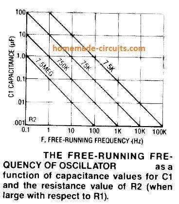
The graph above provides us with the relationship between R1, and C1.
R2 is ignored here because its value is negligibly small compared to R2.
Basic Square wave oscillator circuit using IC 555
From the above discussion I have explained how an IC 555 can be used in it astable mode to create a basic squarewave oscillator circuit.
The configuration allows the user to vary the values of R1, and R2 right from 1K to many mega ohms for getting a huge range of selectable frequencies and duty cycles at the output pin 3.
However, it must be noted that R1 value shouldn't be too small since the effective current consumption of the circuit is determined by R1. This happens because during each C1 discharge process pin 7 attains the ground potential subjecting R1 directly across the positive and the ground line. If its value is low, there may be a significant current drain, increasing overall consumption of the circuit.
R1 and R2 also determines the width of the oscillatory pulses produced at pin 3 of the IC. R2 specifically can be used for controlling the mark/space ratio of the output pulses.
For the various formulas for calculating the the duty cycle, frequency, and PWM of a IC 555 oscillator (astable) can be studied in this article.
1) Variable Frequency Oscillator using IC 555
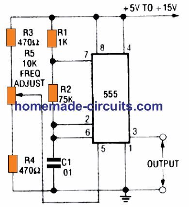
The astable circuit explained above can be upgraded with a variable facility which allows the user to vary the PWM and also the frequency of the circuit as desired. This is simply done by adding a potentiometer in series with the resistor R2 as shown below. The value of R2 must be small compared to the pot value.
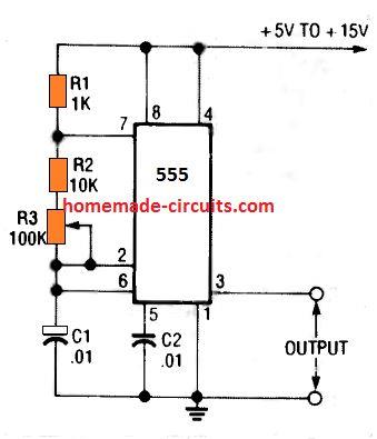
In the above set up, the frequency of oscillation can be varied right from 650 Hz, to 7.2 kHz through the indicated pot variations. This range can be even further increased and enhanced by adding a switch for selecting different values for C1, since C1 is also directly responsible for setting the output frequency.
2) Variable PWM Oscillator Circuits using IC 555

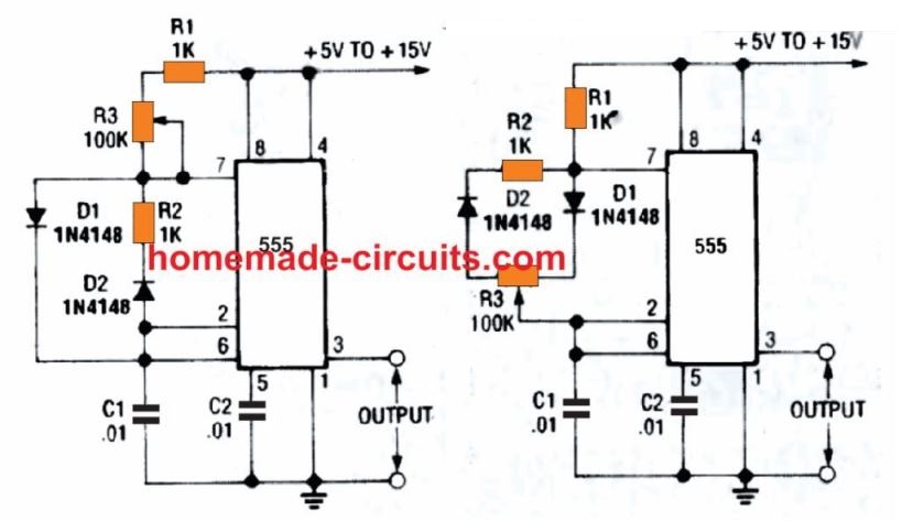
The figure above shows how a variable mark space ratio facility can be added to any basic IC 555 astable oscillator circuit through a couple diodes and a potentiometer.
The feature allows the user to get any desired PWM or adjustable ON OFF periods for the oscillations at the output pin 3 of the IC.
In the left side diagram, the network involving R1, D1, and the pot R3 alternately charges C1, while the pot R4, D2 and R2 alternately discharges the C1 capacitor.
R2, and R4 determine the rate of charge/discharge of C1, and can be adjusted suitably for getting the desired ON/OFF ratio for the output frequency.
The right side diagram shows R3 position shifted in series with R1. In this configuration, the charge time of C1 is fixed by D1 and its series resistor, while the pot only allows the control for the discharge time of C1, hence the OFF time of output pulses. The other pot R3 essentially helps to alter the frequency of the output instead of the PWM.
Alternatively, as shown in the above figures, it may be also possible to connect the IC 555 in the astable mode for discretely adjusting the mark/space (ON time/OFF time) ratio without affecting the oscillatory frequency.
In these configurations the length of the pulses inherently increases as the interval of space is reduced, and vice versa.
Due to this, the total period of each square wave cycle remains constant.
The main feature of these circuits is the variable duty cycle, which can be varied right from 1% to 99% with the help of the given potentiometer R3.
In the left side figure, C1 is charged alternately by R1, the upper half of R3, and D1, while it's discharged by means of D2, R2, and the lower half of potentiometer R3. In the right side figure, C1 is alternately charged via R1 and D1 and the right half of potentiometer R3, and it discharged through the left half potentiometer R3, D2, and R2.
In both the above astables the value of C1 sets the oscillatory frequency to around 1.2 kHz.
3) How to Pause or Start/Stop IC Astable Oscillator Function with Push Button
You can trigger an IC 555 astable oscillator ON/OFF in a few simple ways.
It can be done using push buttons or through an electronic input signal.
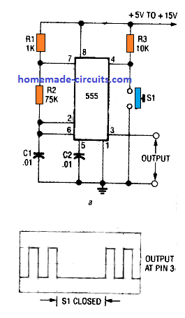
In the figure above pin 4 which is the reset pin of the IC is grounded through R3, and a push-to-ON switch is connected across the positive supply line.
Pin 4 of IC 555 needs minimum 0.7 V to remain biased and to keep the IC functioning enabled. Pressing the button enables the IC astable oscillator function, while releasing the switch removes the biasing from pin 4 and the IC function gets disabled.
This can be also implemented through a external positive signal on pin 4 with the switch removed and R3 connected as is.
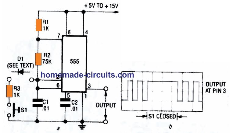
In the other alternative as shown above, pin 4 of the IC can be seen permanently biased via R3 and the positive supply. Here the push button is connected across pin 4 and ground. This implies when the push button is pressed disables the IC output square waves, causing the output to turn 0V.
Releasing the push button commences the generation of the astable square waves normally across pin 3 of the IC.
The same can be achieved through an externally applied negative signal or a 0 V signal at pin 4 with R3 connected as is.
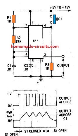
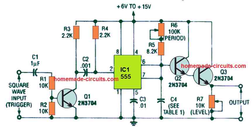
4) Using pin 2 For Controlling Astable Frequency
In our earlier discussions I have explained how the pulse generation of a IC 555 could be controlled through pin 4.
Now we will see how the same may be achieved through pin 2 of the IC as shown above.
When S1 is pressed, pin 2 is suddenly applied with a ground potential, causing the voltage across C1 to drop below 1/3rd Vcc. As we know that when pin 2 voltage or the charge level across C1 is held below 1/3rd Vcc,, the output pin 3 goes high permanently.
Therefore pressing S1 causes a voltage drop across C1 below 1/3rd Vcc forcing the output pin 3 to go high as long as S1 remains pressed. This inhibits the normal working of astable oscillations. When the push button is released, the astbale function is restored back to normal conditions. The waveform on the right side acknowledges the pin 3 response to the pressing of the push button.
The above operation can be likewise controlled using an external digital circuit through the diode D1. A negative logic at the cathode of the diode initiates the above actions, while a positive logic has no effect, and allows the functions of the astable to restore its normal working.
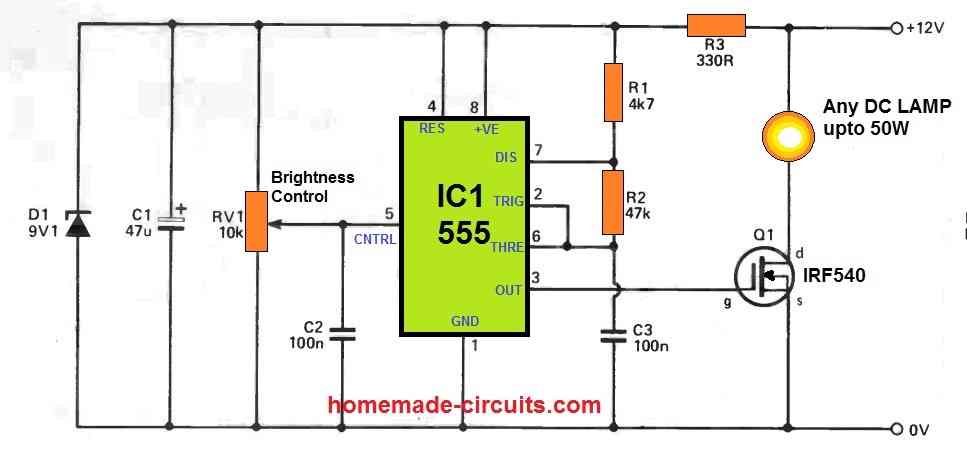
5) How to Modulate IC 555 Oscillator
Pin 5, which is the control input of IC 555, is one of the important and useful pinouts of the IC. It facilitates the user to modulate the output frequency of the IC simply by applying an adjustable DC level on pin #5.
A rising DC potential causes the output frequency pulse width to increase proportionately, while lowering the DC potential causes the frequency pulse-width to become narrower proportionately. These potentials should be strictly within the 0V and the full Vcc level.
In the above figure adjusting the pot generates a varying potential at pin 5 which causes the output pulse width of the oscillation frequency to change accordingly.
Since the modulation causes the output pulse width to change it also affects the frequency, since C1 is forced to change its charge/discharge periods depending on the pot setting.
When a varying AC having an amplitude between 0V, and Vcc is applied at pin 5, the output PWM or pulse width also follows the varying AC amplitude generating a continuous train of widening and narrowing pulses a pin 3.
An AC signal can be also used for the modulation, simply by integrating pin 5 with an external AC though a 10uF capacitor.
To learn how to make Interesting alarm and Siren circuits using the above explained IC oscillator concept, you can read the whole article HERE
Questions & Answers
The circuit for adjustin mark- space ratio without affecting the oscillatory frequency does not seem to be working for me with the supplied values. I need to use the same circuit to control my self made hot air blower using the frequency of around 0.6 to 1hz fixed but be able to vary pulse width. can you please supply me with correct R and C values for the circuit.
Can you please try the following circuit:
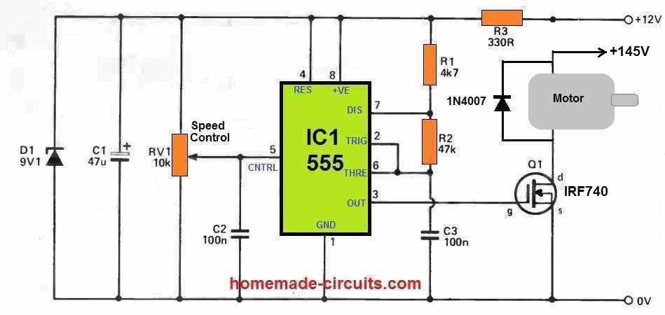
Please ignore the motor and the mosfet stage.
The speed pot can be used to adjust the PWM mark space.
The R1, R2, C1, decides the frequency which can be calculated using this software:
https://www.homemade-circuits.com/ic-555-timer-astable-circuit-calculator/
Engineer..excellent page..I ask.
1..I can measure the frequency I want with a multimeter, that is, a multitester that has to measure frequency..
2..In which pin of the 555 should I measure the frequency to adjust.
Thank you Felix,
Yes a frequency meter can be used to test and set the 555 frequency.
You can attach the meter across the pin#3 and ground for checking and adjusting the frequency of the IC.
Hi. I want to build a circuit with discrete components that works like VCO. I have looked up to circuits with lm555, but this AO works until 2 MHz. I need to work in the range of 0.8 – 2 GHz. It is possible? Is there any AO that I can use? Thanks!
Hi, you might need to use a transistorized astable oscillator for getting that value.
About 25 years back I assembled a circuit using IC 555. It produced a wave — 3 minutes ON and 6 minutes OFF. This, I applied to a mosquito repelling heater through a power transistor. The liquid is vaporized for 3 minutes during the ‘ON’ period and continues to be effective for 6 minutes which is the ‘OFF’ period. This way, there is considerable saving of the liquid (calthrane – a liquid extracted from lemon grass). The operating voltage is 6V. I operated it from a 6V lead acid battery. (I made a different coil)
(I am not an electronics engineer– it is just a hobby)
The idea sounds great, it can save power and the repeller liquid both, thanks for the interesting feedback
I have just built an all-analog 1 GHz spectrum analyzer which works surprisingly well. The only problem is that the signal perceptibly wavers EXCEPT when the sweep rate of the sawtooth signal is adjusted exactly to 50 Hz (mains frequency in Europe). I imagine the AC power line modulates the displayed signal despite all my efforts and precautions to isolate and shield all the circuits and filter and decouple the power lines. The sawtooth is created with a 555 and a constant current source. Can anyone suggest how I could trigger the sawtooth 555 generator from the mains frequency so that the sawtooth never deviates from 50Hz? If more details are needed I will be happy to provide them.
You can refer to the following article, there are some useful designs related to your query:
https://www.homemade-circuits.com/sawtooth-waveform-generator-circuit-using-ic-555/
Many thanks for your prompt answer. Well, yes. That’s precisely what I needed. Do you think I can use a zero-crossing detector to turn the mains sine wave into a square wave and apply it to the 555 pin 2? I will have to find out how to get one single short pulse per cycle (50 Hz = 20 ms) to trigger the ramp. Any further suggestion to achieve this will be most welcome. Thanks again for your help!
You are welcome…here’s one circuit that can be used for converting sinewave to square wave, which you can try:
Many thanks again. Both your suggestions are welcome. I will implement them and the spectrum display will no doubt improve.
No problem, all the best to you!
can u please share a circuit for the bird scare alarms like gun shot alarm to trigger at regular intervals as there is lot of nuisance of birds at our place
I actually have a few gun sound simulator circuits in this site, you can refer them in the following links”
Loud Pistol Sound Simulator Circuit
Make a Simple Machine Gun Sound Effect Generator Circuit
Once this is built, an IC 555 oscillator can be added to toggle the sound every 1 minute
Thank you, sir, for the answer.
I really appreciate it.
I will build it to see, but I’m affraid it is not usable for my project. It is for a mailbox outside that tells me inside that there is post. By blinking.
Dear Sir,
I wonder if you can help me out with this.
I want to build a circuit, bistable, with 2 buttons. The led I want it to blink. The circuit I build
already, but I can’t have the led blinking. Is this possible? Maybe I have to use it with another
led driver or a second 555 IC. The second button is to reset of course. I’m also trying to use it
with a LDR to have the led blinking. The led has to blink but it must stay on, even when it is
dark again, until I reset it with the reset button. I don;t know if this is possible
Thank you.
Hello Pedro, if you want to make the LED blink, then you can replace your existing LED with the following circuit module:
https://www.homemade-circuits.com/how-to-make-single-transistor-led/
Hi Swag; I am a keen boat modeller and require an engine noise generator. As I have three electric motors this is going to be very expensive. I’ve been experimenting with your astables without success. Many years ago I saw a circuit in a journal which used 4 x 555 chips with a ldr connected to pin 5&6 taking a pulse from the motor flywheel which gave a chuff/bang noise and could be tuned at each 555 by a variable pot, all 4 were then integrated by a simple mixer to drive an amp. I’m afraid this is all I can remember about the circuit. I know your very busy but can you help. Best regards Bill
Hi Bill, I found one simple looking circuit in this site, you can just give it a shot, and hope it just works out:
makingcircuits.com/blog/motor-boat-sound-generator-circuit/