The following simple analogue frequency meter circuits can be used for measuring frequencies which may be either sine wave or square wave. The input frequency which is to be measured must be at least 25 mV RMS, for optimal detection and measurement.
The design facilitates a relatively wide range of frequency measurement, right from 10 Hz to a maximum of 100 kHz, depending on the setting of the selector switch S1.
Each of the 20 k preset settings associated with S1 a can be individually adjusted for getting other ranges of frequency full scale deflection on the meter, as desired.
The overall consumption of this frequency meter circuit is only 10 mA.
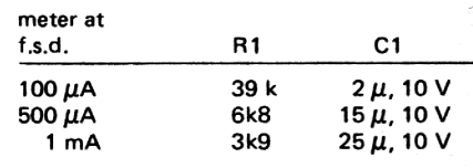
The values of R1 and C1 decides the full scale deflection on the relevant meters used, and could be selected depending on the meter employed in the circuit.
The values could be fixed accordingly with the help of the following table:
How the circuit Works
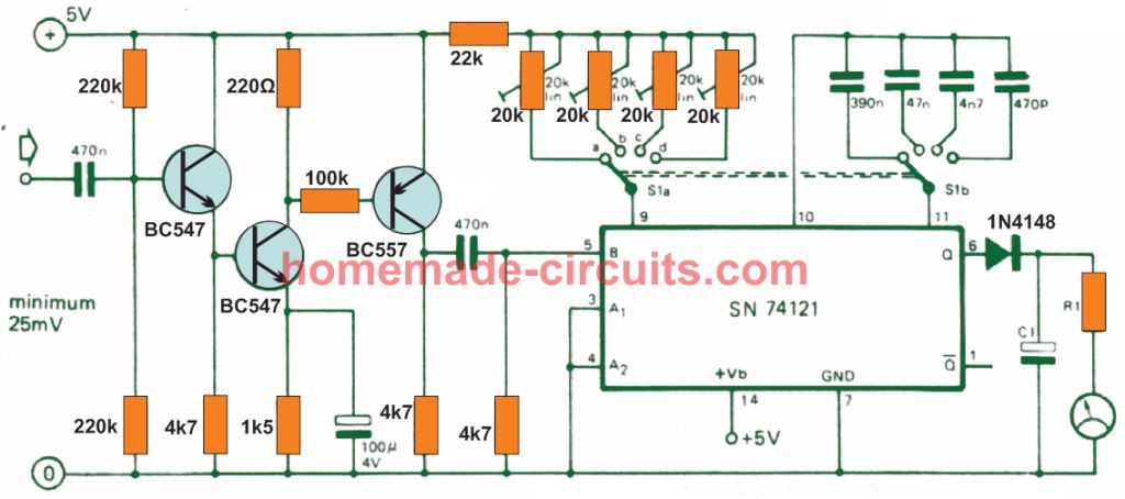
Referring to the circuit diagram of the simple frequency meter, 3 BJTs at the input side work like voltage amplifier for amplifying the low voltage frequency into a 5 V rectangular waves, to feed the input of the IC SN74121
The IC SN74121 is a monostable multivibrator with Schmitt-trigger inputs, which allows the input frequency to be processed into a correctly dimensioned one-shot pulses, whose average value directly depends on the frequency of the input signal.
The diodes and R1, C1 network at the output pin of the IC work like an integrator for converting the vibrating output of the monostable into a reasonably stable DC whose value is directly proportional to the frequency of the input signal.
Hence, as the input frequency rises, the value of the output voltage also rises proportionately, which is interpreted by a corresponding deflection on the meter, and provides a direct reading of the frequency.
The R/C components associated with the S1 selector switch determines the monostable one-shot ON/OFF timing, and this in turn decides the range for which the timing becomes most suitable, to ensure a matching range on the meter and minimum vibration on the meter needle.
Switch Range
- a = 10 Hz to 100 Hz
- b = 100 Hz to 1 kHz
- c = 1 khz to 10 kHz
- d = 10 kHz to 100 kHz
Multi-range Accurate Frequency Meter Circuit
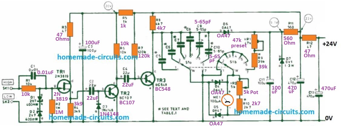
An improved version of the first Frequency Meter circuit diagram is displayed in the above figure. The TR1 input transistor is a junction-gate FET followed by a voltage limiter. The concept allows the instrument with a large input impedance (of one megohm range) and safety against overload.
Switch bank S1 b simply holds the positive ME1 meter terminal "grounded" for the 6 range configurations designated on S1 a and thus supplies the discharge path for the corresponding range condenser as outlined in the remarks to Fig. 1.
That being said, at seventh place, the meter and a preset resistance, VR1, are switched around the D7 reference diode of Zener.
This preset is tweaked during setting up to provide a meter full scale deflection which is then accurately calibrated for that specific reference level.
This is important since Zener diodes on their own offer a 5% tolerance. When fixed, this calibration is finally governed from a dashboard panel potentiometer VR2 which provides the control for all frequency ranges.
The highest amplitude of the input frequency placed on the f.e.t. gate is restricted to approximately ± 2.7V through the Zener diodes D1 and D2, collectively with resistor R1.
In the event the input signal is higher than this value in both polarity, the respective Zener will grounds the excess voltage stabilizing it to 2.7 V. Capacitor C1 facilitates certain high frequency compensation.
The FET is configured like a source-follower and the source load R4 works as an in-phase mode of the input frequency.
Transistor TR2 functions like a straightforward squaring amplifier whose output causes the transistor TR3 to switch on and of as per the explanation previously provided.
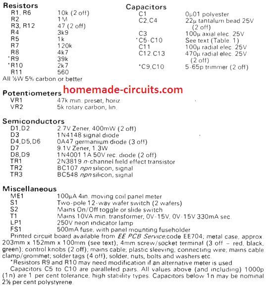
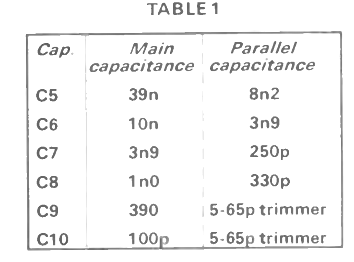
The charging capacitors for every single 6 frequency ranges are determined with the switch bank S1a. These capacitors must be extremely stable and high grade such as a tantalum.
Although indicated as solitary capacitors in the diagram, these could be made up using a couple of paralleled parts.
Capacitor C5, for instance, is built using a 39n and an 8n2, a overall capacity of 47n2, while C10 consists of a 100p and a 5-65p trimmer.
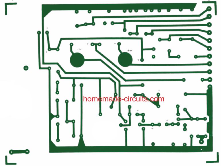
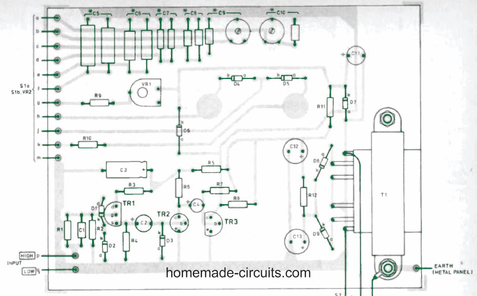
PCB Layout
The PCB track design and the component overlay for the above shown frequency meter circuit is shown in the following figures
Simple frequency Meter Using IC 555
The next analogue frequency measuring device is probably the simplest yet features a reasonably accurate frequency reading on the attached meter.
The meter could be the specified moving coil type or a digital meter set on a 5 V DC range
The IC 555 is wired as a standard monostable circuit, whose output ON time is fixed through the R3, C2 components.
For each positive half cycle of the input frequency, the monostable turns ON for the specific amount of time as determined by the R3/C2 elements.
The parts R7, R8, C4, C5 at the output of the IC work like stabilizer or integrator to enable the ON/OFF monostable pulses to be reasonably stable DC for the meter to read it without vibrations.
This also allows the output to produce an average continuous Dc which is directly proportional to the frequency rate of the input pulses fed at the base of T1.
However, the preset R3 must be properly adjusted for different ranges of frequencies such that the meter needle is fairly stable and an increase or decrease of the input frequency causes a proportionate amount of deflection over that specific range.
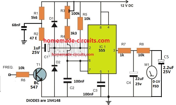
IC 555 Analogue Frequency Meter
The figure below exhibits the 555 IC arranged like a linear-scale analog frequency meter having a full scale sensitivity of 1 kHz. The circuit's power is received through a stabilized 6 V supply.
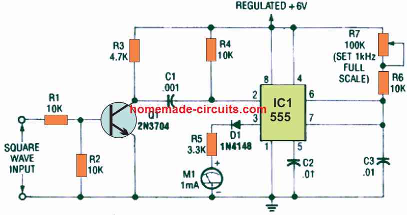
The input signals for this analogue frequency meter can be in the form of pulses or square -wave signals with peak-to-peak limits of 2 volts or higher.
Transistor Q1 amplifies this pulsed input signal sufficiently high to trigger the pin#2 IC 555. The output of the IC at pin#3 is connected with the 1 mA full-scale deflection moving-coil meter M1.
Diode D1 works like an offset cancel stage with the help of multiplier resistor R5.
Whenever the IC 555 which is configured as a monostable multivibrator get triggered by an input pulse, it creates a pulse having a fixed duration and amplitude.
When every single pulse includes a peak voltage of 6 volts and a 1ms period, and it triggers the IC pin#2 with a frequency of 500 Hz, a high logic 500 milliseconds is created at pin#3, in each 1000 milliseconds.
Furthermore, the average value of output from the IC 555 assessed over this time interval can be calculated as
500 milliseconds/1000 milliseconds x 6 volts = 3 volts or half of 6 volts.
Likewise, in case the input frequency is 250 Hz, and a high pulse of 250 milliseconds in each 1000 millisecond period is created.
As a result, the avergae output voltage from the IC now equals 250 milliseconds/ 1000 milliseconds x 6 volts = 1.5 volts or one quarter of 6 volts.
This shows that, the circuit's average value of output voltage, tested within a realistic overall quantity of pulses, is directly proportionate to the repeating frequency of the monostable multivibrator.
We can get only mean or average measurements from moving-coil meters. In the circuit diagram a 1 mA meter can be seen connected in series with multiplier resistor R5.
This resistor R5 adjusts meter's sensitivity at approximately 3.4 volts full-scale deflection. The meter is hooked up to offer the mean output value of the multivibrator and its display is instantly proportional to the input frequency.
Using the part values as indicated in the analogue frequency meter diagram, it is configured to produce full-scale deflection at 1 kHz.
To set up the circuit, at first, a 1 kHz square wave frequency is applied to the indicated output, and full scale-adjust potentiometer R7 (it regulates the pulse length) is adjusted and fixed to provide a full-scale measurement on the meter.
Simple Frequency Meters using NAND Gates
The simple NAND gate based frequency meter circuit shown below represents an optimal balance of the desired features.
I seamlessly integrated it into a Wien bridge-type audio oscillator, which I had constructed earlier, using the meter to monitor the output frequency.
This configuration offers a clear advantage in that it eliminates the reliance on dial calibration, a factor susceptible to numerous sources of error.
Based on the tests I've conducted so far, the linearity and stability achievable with this circuit are surprisingly impressive, spanning the entire range of my oscillator from 20 Hz to 200 kHz.
The circuit is founded on the utilization of CMOS NAND gates configured in a straightforward monostable setup.
It generates an output current signal that maintains a linear relationship with the input frequency.
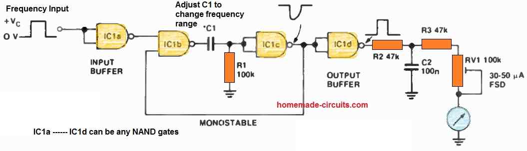
Within this monostable setup, the central components are formed by two gates, IC1b and IC1c, extracted from a quad package. IC1a and IC1d serve as input and output buffers, respectively, primarily tasked with squaring up any rounded signal edges at both ends.
The output from IC1d manifests as a series of positive rectangular pulses, each possessing a consistent width determined by the time constant RI x C1.
These pulses exhibit a frequency equivalent to the input frequency. Subsequently, these pulses undergo integration, yielding a resultant signal that's fed into a meter with an appropriate level of sensitivity.
I employed a standard multimeter movement with a 30 uA Full-Scale Deflection (FSD) sensitivity, although there's potential to use a less sensitive movement, such as a 1 mA FSD, with corresponding adjustments to the values of R2, R3, and VR1.
Specifications
IC1 = 74C00, 4011 etc.
Vc = + 5 V to + 12 V REG.
PIN 14 of ICI = +Vc
PIN 7 of ICI = 0 V ( GND)
SELECT C1 FOR FREQUENCY RANGE
How to Calibrate
Calibration relies heavily on the chosen component values, meter sensitivity, and potential variations between ICs from different manufacturers.
Thus, some experimentation with component values may be required, and the provided values should serve as rough guidelines.
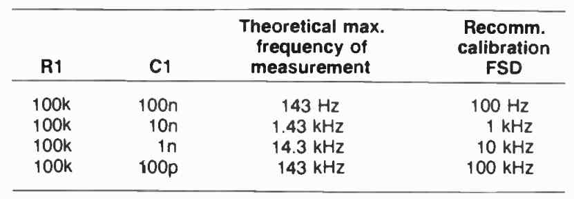
With any combination of R1 and C1, the upper frequency limit for measurement hinges on the product of R1C1.
A general rule of thumb is to select R1C1 to be equal to 1/fmax, where fmax corresponds to the desired input frequency for full-scale deflection.
By using an input signal with a known frequency, VR1 can be adjusted to achieve an appropriate meter deflection.
Adapting to different frequency ranges is possible by switching in different C1 values while keeping other component values constant.
For instance, to expand the range by a factor of 10, simply decrease the value of C1 by 10 and vice versa.
Some fine-tuning of component values may be necessary.
Calibration also hinges on the regulated supply voltage, which should be maintained consistently. I utilized a 12 V mains-powered regulated supply, but if a 9 V battery is employed, I recommend employing a series regulator with low standby current, such as the uA105.
Improved Design
The next analogue frequency meter design presented below is a modified version of the above design, delivering excellent performance.
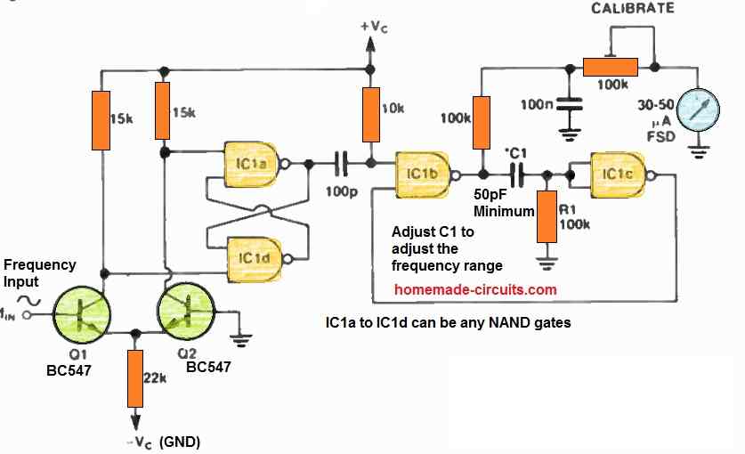
It proves especially valuable when the input signal requires conditioning, such as transforming low-level sine waves into a square wave input for the monostable section of the circuit.
Fundamentally, IC1a and IC1d are configured as a flip-flop that undergoes a swift change in output state when the inputs to these gates alternate between low and high.
Multiple methods exist for driving this type of flip-flop, but in this instance, I opted for a pair of transistors configured as a differential amplifier.
This setup offers the advantage of being DC-coupled to low-frequency, ground-referenced signals, while also providing a moderate level of signal amplification.
However, it necessitates a dual power supply. The input sensitivity surpasses 200 mV peak-to-peak, contingent on the transistor gain and supply voltage
Frequency Meter Circuit Using LM358 IC
At the heart of this circuit lies the application of an input waveform, skillfully routed via components C1 and R1, ultimately arriving at a pair of diodes, D1 and D2.
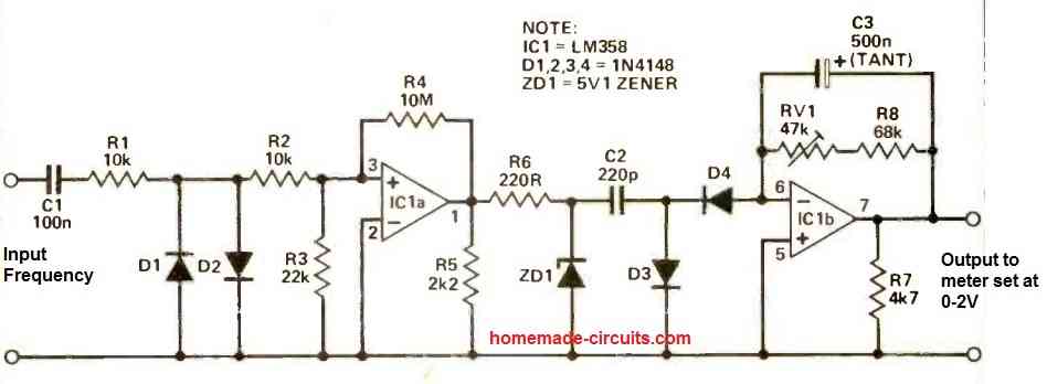
What makes this arrangement remarkable is its ability to accommodate input voltages that substantially surpass the supply voltage, all without causing any disturbance to the LM358, a vital op-amp in this setup.
To delve deeper, the design employs the strategic utilization of resistors R2 and R3, which work in tandem to effectively curtail the input voltage.
This dynamic prevents the op-amp from venturing beyond its operational thresholds, particularly when faced with negative excursions of the waveform.
It's worth noting that while strictly speaking, operating below 0V (reference voltage) on pin 3 could be considered exceeding operational limits, the specifics of this application render it a non-issue.
For those intrigued by this subtlety, or seeking a comprehensive understanding, the inquisitive minds are encouraged to consult the knowledgeable "Auntie Static."
A crucial element, IC1a, serves as a comparator within the circuit.
Working in harmony with IC1a, resistor R4 introduces a touch of hysteresis, enhancing the reliability of switching behaviors.
Meanwhile, resistor R5 assumes the responsibility of pulling down the output to 0V when encountering low outputs.
Moving forward, the synergy between R6 and ZD1 plays a key role in imposing a well-defined upper limit on the voltage supplied to C2, safeguarding the system.
The functioning of IC1a's output unveils another layer of ingenuity. In its high state, current flowing from the 'right-hand' terminal of C2 finds its way to the ground via diode D3.
Conversely, a low output prompts current to flow into the right-hand plate of C2 via D4. This journey is facilitated by the virtual earth anchored at IC1b pin 6.
While RV1 and R8 could theoretically yield a voltage proportional to the instantaneous current from pin 6 through the workings of IC1b, the introduction of C3 lends a smoothing effect, rendering the output from IC1b proportional to the average current.
To maintain equilibrium, R7 steps in to pull down the output to 0V during instances of absent input.
The very essence of this design comes to life in a simple yet effective rule of thumb:
vout = fVC2(RV1 + R8), where 'f' stands for the input frequency, and 'V' signifies the zener voltage.
This rule elegantly empowers engineers to calculate component values for different ranges, enhancing the versatility of the circuit.
One component that demands special attention in this configuration is C3.
A carefully selected compromise, C3 balances the reduction of output ripple, achievable by increasing its value, against the extension of settling time, an outcome of larger C3.
For those aiming to measure ultra-low frequencies, the path is clear: a larger C3 becomes indispensable, smoothing out the ripple with greater efficiency.
1 MHz Frequency Meter Circuit
In the quest to read frequencies that exceed the 20kHz threshold, a practical avenue emerges through the utilization of a pre-scaling circuit.
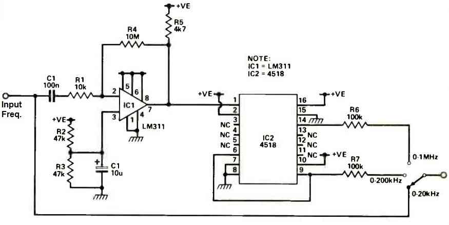
This circuit artfully manipulates the input signal, preparing it for a journey of frequency exploration.
Central to this operation is IC1, which transforms the input signal into a square wave, setting the stage for subsequent actions.
Taking the reins from IC1, a dual decade counter represented by IC2 comes into play. This counter expertly divides the input frequency, laying the groundwork for accurate frequency measurement.
The division options are clear: the signal can be divided by factors of 10 or 100, each choice leading to distinct outcomes.
Dividing the input frequency by 10 alters the output dynamics of the frequency meter. In this configuration, an output voltage of 1V corresponds to a frequency of 100kHz.
Opting for a more extensive division by 100 leads to an even more intriguing scaling effect.
Here, every volt of output represents a frequency of 1MHz, potentially stretching the measurement range up to 2MHz, depending on the specific IC311 variant employed.
What sets this pre-scaling circuit apart is its ability to facilitate the creation of a multi-range instrument without the need for elaborate adjustments.
The role of RV1 evolves into a tool that maintains accuracy across ranges. By configuring RV1 for the 0 to 20kHz range, this setup effectively preserves its precision as frequencies ascend to higher levels.
Parts List
RESISTORS (all 1/4W 5%) R1 10k
R2 = 10K
R3 = 22K
R4 = 10M
R5 = 2.2K
R6 = 220R
R7 = 4.7K
R8 = 68K
RV1 = 47K
CAPACITORS
C1 = 100 nF Ceramic
C2 = 220 pF Ceramic
C3 = 500 nF Tantalum
SEMICONDUCTORS
IC1 = LM358
D1-4 = 1N4148
ZD1 = 5V1 Zener
MISCELLANEOUS
PCB; PP3 battery connector; PP3 battery; BC3 case with battery compartment; On/off switch, rotary switch and knob and other parts for pre -scaler, if required.
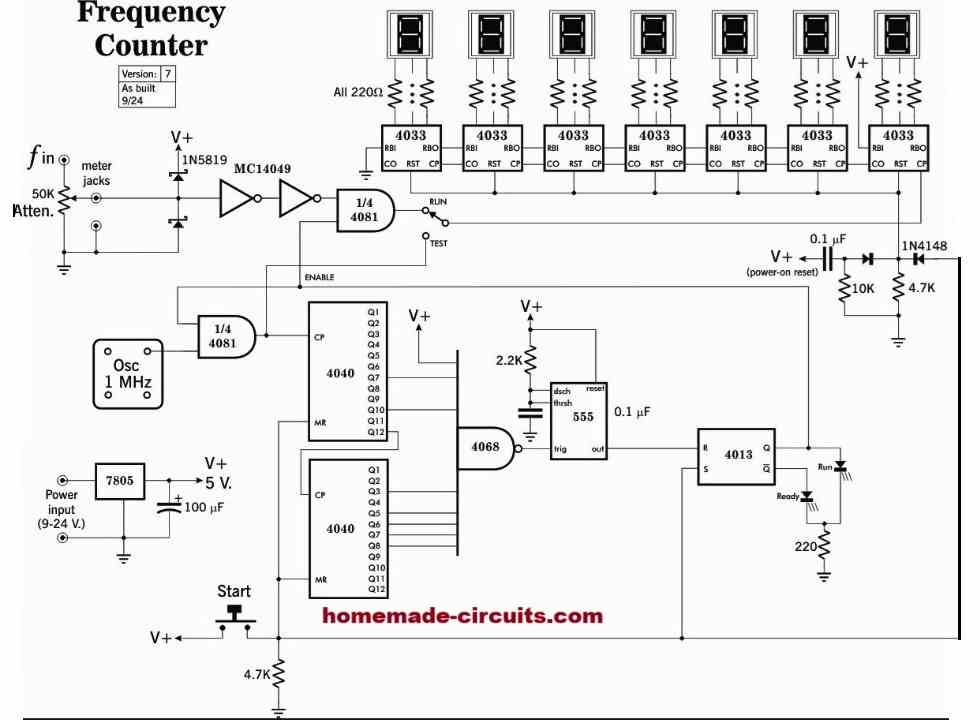
7 Digit Frequency Meter Circuit using IC 4033
The following frequency meter circuit, using IC 4033, was generously contributed by a dedicated reader and passionate electronics enthusiast, Electron Orbit. After successfully building and testing the project, he graciously submitted it for publication on this site. I extend my sincere thanks to Electron Orbit for his valuable contribution and thoughtful gesture in helping other readers.
Let's hear it from the electron Orbit himself:
Circuit Description
I'm writing you to show you a project I just successfully completed that you might be interested in.
I was hoping you might look it over and tell me what you think. It's a frequency counter;
I'm working on some projects where it'd be useful to know the frequency of a circuit, so I decided to build my own. I looked at quite a few designs online, including some on your site, I think, but wasn't all that happy with any of them.
The thing I didn't like about the ones I saw was the time-window generation: almost all of them used a 555 to generate the 1-second acquisition window. Now I am a fan of the 555 for many purposes, but in this case it just didn't seem accurate enough. (Or let's say that the accuracy could definitely be improved on!)
So I scratched my head, looked at datasheets, and came up with the scheme I ended up using, which is totally digital and driven by a crystal oscillator, so quite accurate. I think what I came up with to achieve this is pretty clever if I don't say so myself, even though it's kind of a roundabout way of doing things. If you look at my schematic, you'll see a couple of 4040 counters driven by the oscillator.
What I did was look at the magic number I wanted, which is 1 million. In hexadecimal it's F4240. Breaking that down into 5 4-bit nybbles:
1111 0100 0010 0100 0000 So I wired the outputs from both counters to an 8-input AND/NAND, using the corresponding Q-outputs, so that when this bit pattern was reached the AND would go high. (Actually I ended up waiting for the NAND to go low, for reasons explained below.)
Well, the first time I put this together on a breadboard it didn't work. I started tearing my hair out, since it looked like it should work, until I realized that the problem was most likely that that pulse was too short to reset the flip-flop to stop the counter.
Which was proven true when I stuck in a one-shot (monostable), using a good old 555 to lengthen that pulse. (I had to use the NAND output, since the monostable needed a low pulse rather than a high one.) Then it worked like a charm!
So like I said, a pretty roundabout way to do things, but it works. I can think of at least 2 other ways to do this with the same accuracy; if I were to do this over again I'd probably opt for using some decade counters to divide down the 1 MHz clock to 1 Hz. Or one could use that pair of chips, ICM7207/7208, which seem custom made for a frequency-counter application. (I believe you've covered them somewhere on your site?)
Anyhow, here it is. It works pretty well, well enough for my purposes. It could use better input conditioning, maybe a preamp stage (opamp) so it would work with weak signals. But not bad for an electronics amateur. (I'm in no way on your level; I know enough about electronics to get into interesting trouble, but I am learning as I go along.) I should point out that I did have help from a friend who knows a lot more about electronics than I do.
Thanks for all the work you put into your website; it's useful stuff (and higher quality than a lot of similar-looking garbage sites online!).
Electron Orbit
Circuit Diagram
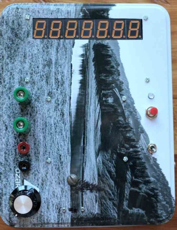
Prototype Image (Internal View)
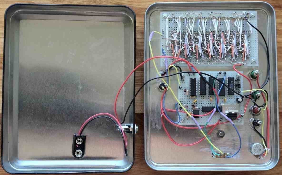
Finalized Prototype Image (External View)


Questions & Answers
Hello, I want to ask about the first circuit using the IC SN74121. I’m attempting to make a circuit which takes a 25V, 50Hz, Sin wave signal, and it will turn off a load if the frequency drops below a certain point.
I can see that the output voltage is proportional to the frequency, which seems like it’ll help here. If I make some adjustments so the 25V input is reduced to 5V, do you believe this circuit will be suited to the task?
With warm regards from an electronics newbie,
Liam
Hello Liam,
yes that should work according to me! If you reduce the 25V to 5V DC for the circuit as per the circuit schematic, then it should be perfectly fine.
Awesome! Also, the LHS of the image is cut off and I can’t read what the input is for the 470nF capacitor. Is this just the input signal?
My pleasure! At the 470nF input side it is written “minimum 25mV”, meaning the input frequency must be at least 25mV or above. Yes that’s where the input frequency in question must be applied, with respect to ground.
Hi Swagatam, just letting you know the circuit worked after adding a comparator at the SN74121 output. With a few adjustments, when the frequency drops below 48Hz a load will turn off. Thank you for posting your build, you’ve helped me a bunch!
Thank you Liam, for updating the results. Glad it is now working for you as per your specifications. Please keep up the good work!
What should I connect on pin#4 and pin#8 of LM358 to ensure that the circuit works correctly?
You can connect capacitors and a 1N4148 diode across the supply pins of the IC to make the IC stable.
Good afternoon,
I am currently working with a RF pickup sensor. The sensor gives a very weak signal, and the flow meters we are using can not register the signal. What I need to do to fix this is amplify the signal to be in the 0-5V / 0-24V range, and convert it to a digital signal.
Best regards,
Antun Vujica.
If you want amplify the RF signal, you can probably try the first circuit from the following article:
https://www.homemade-circuits.com/small-amplifier-circuit/
Please try tis first then we proceed with the digital conversion….
I have a Westinghouse mains frequency meter,type kx-241,I uses a separate transducer.I do not have this device,the meter itself is centre reading ,it is a 100 ma dc meter.I would like to get this meter working.the mains here are 230vac 50 cycle.are any of your circuits suitable?Many thanks
You can use the 100 mA meter with the IC 555 frequency meter explained in the above article, with minor modifications.
Hello.
In the first circuit that you have given, which meter are you using to measure the voltage that is proportional to the input frequency ? Is that a galvanometer or voltmeter ?
Hi, It is a moving coil type voltmeter. I would recommend you the following circuit, which is a tested design:
Hello.
I must read the frequency of a generator whose voltage varies between 15 and 250 vac and 15 to 70 hertz and works outside -40 C to + 40C
The best for me is to read square wave 50/50 or 0 to 5 vdc with microprocessor.
Can you help me ?
Best regards
Denis
Hi,
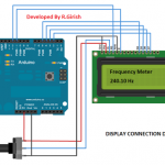
you can try the following concept:
https://www.homemade-circuits.com/frequency-meter-circuit-using-arduino/
Make sure to add a 330K resistor in series while feeding the frequency to the above circuit.
Dear Sir,
Please sir, I need a schematic diagram for digital frequency meter
Hi Godfrey, you can try the following design:
https://www.homemade-circuits.com/5-digit-frequency-counter-circuit/
Hello Mr. Swagatam, Planning to build the Multirange Meter above.
What are the values of C5 to C8? Is the panel meter 100 milliampere? How to calibrate? Like your site a lot. Building this circuit to show my 17 yo son how we used to do these things. I think the experience will give him a different perspective on the digital world of today. Look forward to hearing from you. Sincerely, Richard Ellington (85 years old/built my first kit, a Heathkit VTVM, when I was 14)
Hello Richard, thank you for your interest in this project.
I have added the table for selecting the capacitor ranges.
The meter is a 100 micro amp meter
Soon I may also add the info regarding how to calibrate it.