A bridge rectifier is an electronic network using 4 diodes which is used for converting an AC input to DC output. The process is called full wave rectification.
Here I have explained the basic working principle of rectifier diodes such as a 1N4007 or a 1N5408, and also learn how to connect 1N4007 diodes to build a bridge rectifier circuit quickly.
Introduction
Diodes are one of the important electronic components used for rectifying an AC into DC. Diodes have the property of allowing DC through a specified direction and rectifying AC across its pin outs. Let’s learn the components more elaborately.
Diodes are tiny electronic components which are normally recognized by their cylindrical black colored body having a white band at the edge of their body.
Diode Pinouts
They have two pin across the two ends of their body.
The pins also called leads are assigned with appropriate polarities termed as the cathode and the anode.
The terminal coming out from the banded side is the cathode while the opposite termination is the anode.
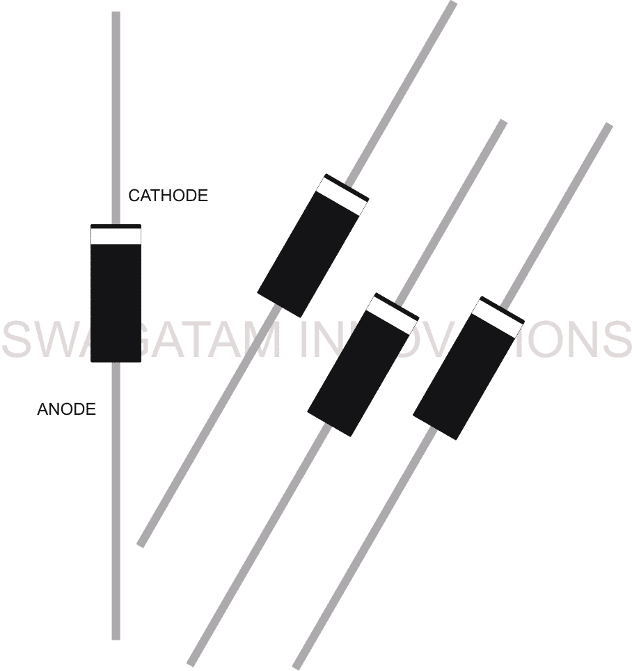
The black colored diodes are normally rated at higher amps while the smaller ones which are red in color are much lower with their power rating.
The power rating suggests how much current can be passed across the device without heating up the part to damaging levels.
Diodes have one important function which becomes their sole property. When an alternating current is applied across the anode and the ground of a diode, the output across the cathode and the ground is a direct current, meaning the diode is able to convert an AC to DC through a process called rectification.
How does Rectification in Diodes Take place
We know that an alternating current is made up of a voltage content which is not stable, meaning the voltage and the current flow constantly changes its polarity from zero to the given highest voltage peak, then it falls back to zero, then reverts to the negative polarity and heads toward the negative voltage peak and gradually falls back to the zero mark for repeating yet another similar cycle.
This repeated change of polarity or the cycles may have a specific tome periods depending upon the frequency of the AC or vice versa.
When the above AC is introduced at the anode of a diode with respect to ground, the negative cycles are blocked by the diode and only the positive cycles are allowed to pass which appears at the cathode of the diode with respect to the ground.
Now if the same AC is applied across the cathode of the diode with respect to the ground, the positive cycles get blocked and we are able to receive a only the negative cycles with respect to the ground.
Thus depending upon the polarity of the diode, the applied AC is effectively rectified such that only a specified voltage appears at the other end or the output of the device.
In case it is required to process both the cycles of an AC for better efficiency and for getting a completely rectified AC, the use of a bridge rectifier is employed.
A bridge rectifier configuration is a smart arrangement of four diodes such that the applied AC across the network results in the rectification of both the halves of the AC cycle.
It means the positive half as well as the negative half cycles are both converted to positive potentials at the output of the bridge configuration. This arrangement results in a better and a more efficient of an AC signal.
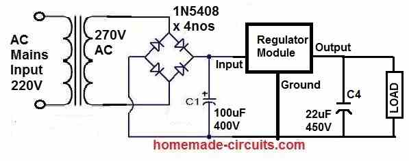
A filter capacitor is normally used at the output of a bridge so that the notches or the instantaneous voltage blackouts can be compensated through the charge stored inside the capacitor and for generating an well optimized and a smoother DC at the output.
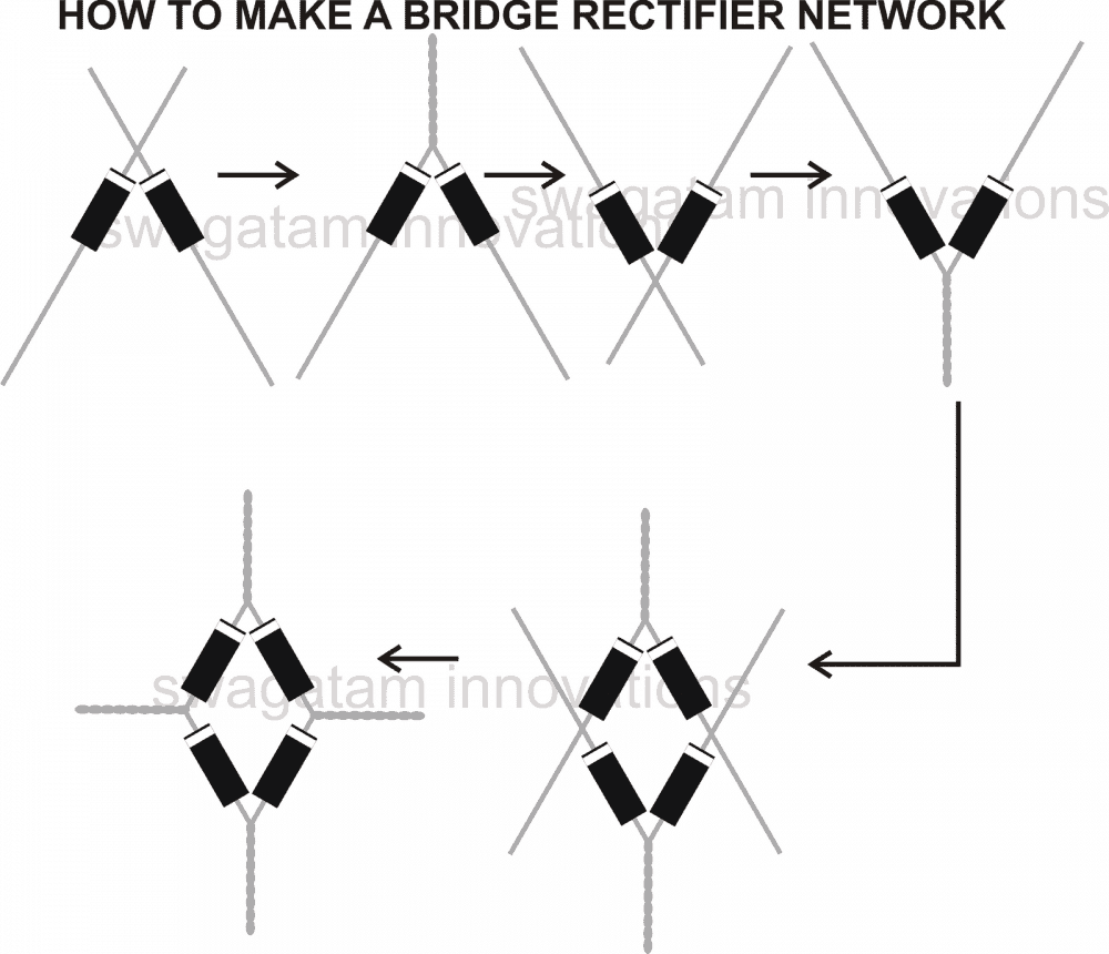
How to Make a Bridge Rectifier Circuit using 1N4007 Diodes
Making a bridge rectifier using four 1N4007 diodes is not at all a difficult task. Simply by twisting the terminals of the four diodes in a specific pattern, a bridge rectifier can be made within seconds.
The following steps may be incorporated for making a bridge rectifier:
- Take four 1N4007 diodes.
- Pick two of them and align there banded sides or the cathodes together such that they are held in an arrow like shape.
- Now twist the terminals tightly such that the joint holds the orientation intact. Keep this joined pair of diodes aside.
- Now pick the remaining couple of diodes and repeat the above procedure, however make sure now the opposite ends or the anodes go through the above explained steps.
- Finally it’s time to fix the final bridge network, which is done by integrating the above two assemblies together with their respective free ends as shown in the figure.
- Your bridge rectifier design is ready and may be used for the intended application.
Alternatively the above explained method of making a bridge can be followed over a PCB also by inserting the diodes in the PCB as per the explained orientations, and by soldering them at the required places.
Questions & Answers
Hi Swagatam.
I have a interesting setup and looking at using a Diode to stop my two battery inverter fighting between each other sending power back and forth to each battery.
right now I have time switches setup with one inverter on a set discharging.
But would like a different setup.
what would you recommend please.
best regards
Eddie
Hi Eddie,
do you want the batteries to work alternately, one after the other, that is when one discharges fully, the other one replaces it and so on?
In that case you can try the circuits from the following article:
https://www.homemade-circuits.com/automatic-dual-battery-charger-with/
Is there any specific type of diode that I should use with a piezoelectric pressure sensor setup?
Which piezo-electric circuit are you referring to?
sir if any 72v, 15amp power supply ckt diagram.
You can refer to the following article, and for further questions post under the same article:
https://www.homemade-circuits.com/how-to-design-a-stabilized-bench-power-supply-circuit/
sir hope ur ok . im searching for a bridge recifier GPJ 2506 rating 36vdc 65amps for battery charger type E230 G 3665 B25-FP pse consider and advice im in KENYA EAST AFRICA
Hi Silas, sorry, I have no idea where in Kenya this specific bridge rectifier can be found. I am located in India.
Ok thanks sir
sir i want required 0 to 100v voltage and current controller ckt diagram 15amps.
for battery charging.
You can try the following design:
Sir in this ckt current variation resistance value not mentioned.
Current resistance can be calculated using the following formula.
R = 0.7 / Max Current
hai sir , i have small dought ,sir i can give transformer based o power supply 220vac, to74vdc,for 10amp charging , e bike operating voltage 72vdc LFP battery, 40ah.
sreenivasulu, You should have asked this question under a battery charger article, so please make sure to comment under the right article next time.
You can supply the DC from an SMPS or a transformer power supply it does not matter. But the voltage and the current must be controlled as per the battery specifications.
swagatam sir ups transformer 6v 0v 6v centertap winding after connecting series 0v 13v, after bridge rectifire 16v dc increasing [with filter capacitor 3000mfd,63v dc]. pls explain reson , can charge lead acid battery 12v,63ah.
Sreenivasulu, When the rectified DC from bridge rectifier is filtered using a filter capacitor, the RMS of the DC ripples is converted to its DC peak value by a factor of 1.41.
In your case 12 RMS x 1.41 = 16.92 peak DC.
You will need to regulate this voltage to 14V 7 amps for charging your 12 V 63 Ah battery.
any regulating ic number sir
You can try the following idea. Replace the transistor with 2N3055, resistor with a 100 ohm 2 watt. Experiment with the zener value until you get 14V at the output. While checking the 14V make sure to connect a 1K resistor across the output
sir pls draw ckt diagram
thank u sir ur gud suggition .
You are welcome!
Okay sir what if it is higher
then this diode will also heat up, please confirm the current first before deciding on the diode
Okay please sir how can I make it work perfectly what type of diode should I use the battery is 13volt battery likewise the fan please sir what type of diode should I use
Henry, you can use a 1N5402 rectifier diode considering the fan current consumption is less than 1 amp.
Please I used a diod to make a DC 12volt to flow In one direction to a DC 12 fan but when it is connected the diod will start burning please what could be the cause
It is because either you fan and the supply voltage are not compatible, and your fan is consuming large amount of current, or simply because your diode current handling capacity is low compared to the fan’s consumption
Well I feel pretty stupid right now, the bridge rectifier I made was built correctly and after testing the dc voltage with my DVM I decided to check with Old Faithful, my Simpson 260 VOM, and found the dc voltage was correct and the issue was that I had the DVM on the wrong scale. Thanks for time in answering my problem.
Gerry
No problem at all, glad the issue is finally solved.
I am working on a GE model 650 portable tube radio that has a selenium rectifier to convert 120 volt ac to 90 volt dc, I read that this needs to be replaced with a bridge rectifier so I looked and found many articles on how to build one using diodes. After following the instructions and making my home made rectifier I put power to the ac inputs as on the diagram and checked the dc output as instructed and the amount of dc voltage was 60 volts dc. As I understand it there should be a voltage loss but not a 50% loss,I have checked and double checked the construction and everything is as the diagram shows, can you please let me know what may be the problem. I am using 1N5404 diodes for the rectifier which are rated 3A 400V. Thank you.
Since each diode is supposed to drop around 0.6 V, and the AC cycles are supposed to pass through two series diodes, the total drop should be around 1.2 V, which means the output should be 120 – 1.2 = 118. 8 V.
If you are getting 60 V then something’s not right with your bridge rectifier. Did you make the connections in the following manner, please ignore the capacitor:
Hi sir.. I have made a diode bridge with 5804 diodes and 2200mF cap with input voltage of about 25v AC. Later I added lm317 stage for a variable supply of 0 to 30v DC. But when I measure the AC voltage at the output of lm317 ,it always show about double the DC voltage value at that pot position. For 30v DC, I’m getting 65v AC even after connected another 1000mF after the regulator stage. I can’t figure out what is happening. My valuable led VA meter burned away when I tried to measure the DC using it. Pls help how to cutoff this ac or reduce it to a minimum. I noticed that most smps wall adaptors give AC voltage at the output. How is it so?? Need Ur help sir.. thanking
Hi Binoj, what is the voltage that you are getting just after the bridge rectifier? If your input voltage is 25V then the voltage after the bridge should be 25 x 1.41 = 35V.
Please confirm this first. With 35V at the input of the LM317, it is strange and impossible to get 65V at the output of the LM317.
Connect a heavier load at the output and check the voltage again.
I am wiring in a dual speed radiator fan according to the diagram at this location:
However, I need your opinion as to whether the 1n5408 diode (top center of picture) should be in-line or grounded.
Thanks
To suggest about the diode I must first know what is the purpose of the diode and I can know that only when I can visualize the contacts of the relay. In your image it is unclear how the relay contacts are wired….the relay diagram should be in a schematic format.
Or if you could tell me the purpose of the relay then I can suggest about its placement.
What is required to estimate the capicity of a smoothing capacitor across the DC output?
It will depend on the load, more info is given in the below link
Calculating Filter Capacitor for Smoothing Ripple
Dear Sir Swagatam
Can I use 1n4007 to build a Full Wave Rectifier for 24 AC volts (3 amp)
Thank you so much
Best regards
vu
Dear Vu,
for 3 amp 1N4007 will not be enough, you must use 1N5408 or 6A4 diodes
Dear Sir Swagatam
Due to poor understanding of electronics I think
1n4007 (data sheet) is 1 amp x1000v =1000 watts
and 24 vac x3 amps = 72 watts
Thanks to you that now I know it must match with the current (amp.) not the voltage.
Thank you so much for your time help me.
Best regards
vu
No problem Vu,
you are getting 1000 watt because of the 1000 V, but here we are interested in the current rating not the wattage. The current is 1 amp, which means the diode will instantly burn at 3 amps.
Please clear my basic conception : AC main line has Phase (live) Line tester glows, and Neutral ( tester does not glows), If i connect Bridge rectifier in Phase & neutral in junction of cathodes of two diode emits Positive Voltage. In positive half cycle of 50hz AC only a single Diode conducting which is forward biased. if no load connected, In negative half cycle other diode of cathode junction conducting.
My doubt is while negative half cycle is the Neutral line of AC converting AC signal to DC. or what ?
Neutral line of AC is not providing +ve what is the purpose of use of 4 diodes.
instead if I connect Anode of one diode in phase line of AC cathode will emit only positive voltage as half wave rectifier.
and if I connect Anode of one another diode in neutral line and Cathode of both diode joining together to get full wave . why not? ( if no load connected) and passing route +ve voltage through a LED and high value resistance to neutral line. Will this work?
Negative half cycle coming from neutral of AC line. ?? Neutral line carries what? or Phase line have both positive and negative half cycle at a 50 times per seconds. ?
if so then why connect with neutral line of Bride rectifier ??
Hope you will clear my basic conception ..As i am new guy tying to understand.
No, sorry your idea will not work, during positive half cycle phase point becomes +220V and neutral is at 0V. During negative half cycles, phase turns into -220V and neutral continues to be at 0V, so in both ways neutral is always at 0V, only the phase changes from +220V extreme to -220V extreme.
For both the cycles the neutral provides the return path, and that’s why a bridge rectifier becomes so ideal in this situation, it provides a clear return path to both the +/- 220V potentials through the load.
if we use only two diodes the effective result will half wave due to lack of return path for the negative cycles.
I want to make a bridge diode rectifier circuit to give an output voltage of 350 volts. Please Help.
you can make it as per the above instructions.
I had a thought which I'd like to run by you.
My boss works with low power home-built three-phase alternators. At the moment, he uses a three-phase diode bridge for the AC->DC conversion, which I am sure you are familiar with.
I presume you are also familiar with active rectification. My thought is:
Would it be feasible to switch the MOSFETs in an active rectifier based on the physical rotation angle of the alternator? For example, with a Hall-effect sensor detecting the magnetic field outside of the spinning alternator, could that work to trigger the MOSFET switching?
I am not very sure, it's difficult to imagine the results without practically verifying the set up, however the concept looks feasible and can be tried.
By the way what could be the benefit of driving the active rectifier without a physical connection when it's easily accessible from the motor??