A variety of small school projects can be built using just two transistors. This compilation includes a collection of practical and fascinating circuit ideas using just a few number of parts.
Any small signal transistor can be used in the proposed two transistor circuit, such as BC547, 2N2222, 2N2907, BC108, BC107, TIP32, TIP31, 188, 8050, 8550, 2N3904 etc.
The transistor type may depend on the output and input specifications of the application.
You may take the help of the chart here.
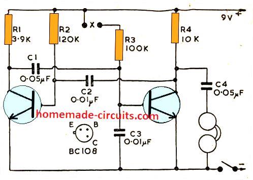
1) Transistor Multivibrator Circuit
It's basically an oscillator circuit which produces alternate ON OFF pulses across its two transistor collectors.
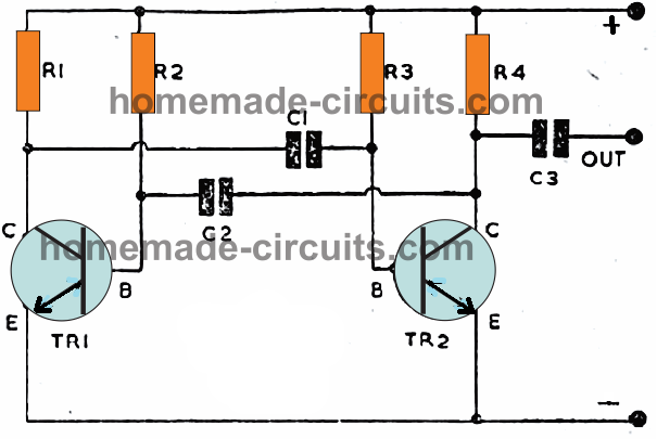
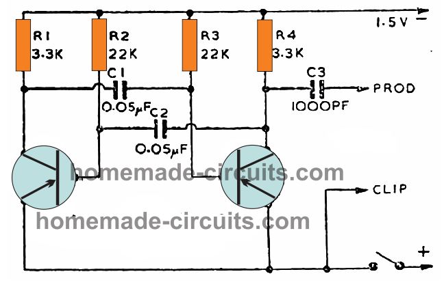
The diagram above depicts the design of a standard transistor astable multivibrator using just two transistors, which in any manner can be implemented for developing various fun projects.
The output which is produced at TR1 collector C is linked to TR2 base by C1, while TR2 collector is connected to TR1 base via C2.
Resistors R1 and R2 supply collector and base currents for TR1, while R3 and R4 source base and collector currents for TR2.
Transistors TR1 and TR2 switch in an alternately switching sequence. The cross-coupling between the two transistor stages causes the design to become unstable in either states. Therefore it begins oscillating continuously as long as it remains powered.
Each BJT sequentially drives one other into conduction, and is also alternately cut-off.
The frequency in which this occurs depends upon the resistance/capacitance or RC time constant value of the circuit.
Meaning through the magnitudes of the resistors, and C2 and C1.
With an appropriate selection of magnitudes, the frequency could be specified to be anything between one or two pulses per second (or even lower) and several kilohertz.
Transistor Astable Multivibrator Applications
The circuit could as a result be applied in pulsating and time delay generating applications.
Additionally, the astable can be used for applications such as in tone generators and audio oscillator applications. C3 works like a coupling capacitor, to acquire the output to subsequent stages.
These applications could include a test probes, headsets, an amp, or perhaps a loudspeaker, based on the specific devices where the multivibrator is employed.
Transistorized astables can work through an extremely low voltages, like from a solitary 1.5V dry cell, and consume a minimal current of just some mAs.
Also these could be enhanced with high collector current transistors variants, for increased output or direct illumination of lamps.
NPN Polarity
Transistor astable can be built with NPB transistors as indicated above. In such designs the emitters are connected to the negative supply line.
Although BC108s have been utilized in the diagram, a variety of other small signal NPN transistors can be employed within this and other similar circuit designs.
Assuming replacements are of NPN type, the negative polarity for the “earth” line must be correctly wired.
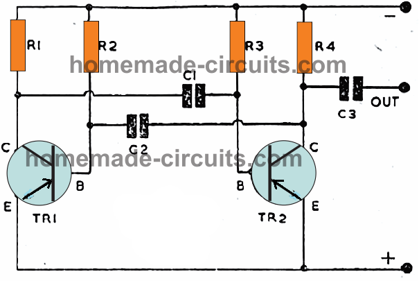
PNP Polarity
In the same manner these can be built using PNP transistors as well.
To avoid misunderstandings, the exactly same circuit is demonstrated above, but using PNP transistors.
The emitter lead has now turned positive. Once again, a common sort of transistor is pointed out (AC128) nevertheless various other PNP transistors may well be tried.
This is fairly frequently possible to work with transistors actually available in the junk box, by replacing other kinds than the ones displayed in the diagrams.
However, always take care of the emitter line polarity for the transistor, which must be positive for PNP and negative for NPN transistors.
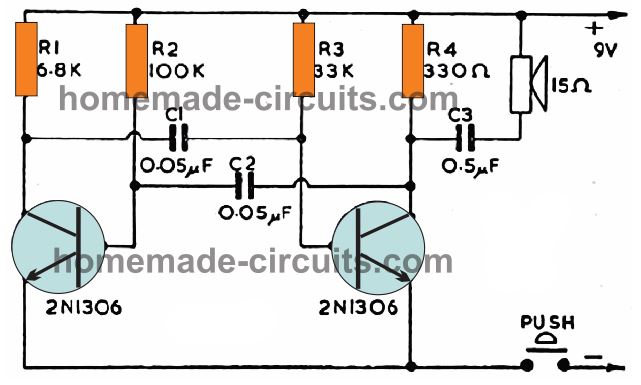
2) Two Transistor Door Bell Circuit
This circuit will probably upgrade your existing door buzzer or electrical bell. This circuit works through a low voltage, DC supply.
This can be a lot easily achieved through a battery, that may have a extended life, because the current utilized is actually little, and the operational cycle is not continuous.
The figure above exhibits the design. The collector of one of the transistors of the astable is hooked up to the speaker via C3. A 15 ohm model is not necessary for this, however a significantly, or high, impedance may lead to a little decrease in volume.
Door Siren Circuit
The circuit below offers identical functions, but it could be organized to provide a louder and high pitched tone.
It could also be quickly designed to present unique sounds in response to subsequent pressing of the button.
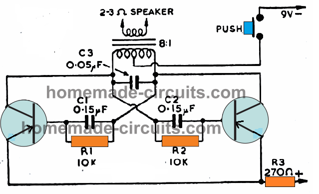
The primary of the transformer supplies the collector load, and each transistor turns ON the base circuit of the other, through the capacitors and parallel resistors C1/R1 and C2/R2.
A transformer that are normally used for loudspeaker impedance matching has been employed here. The ratio of the primary and secondary winding may be around 8:1.
However, this may not be too crucial. The transformer and loudspeaker directly impact the volume level output of the circuit.
It is advisable to work with a ratio greater than 8:1, or an 8 ohm speaker, instead of adjusting the circuit with a transformer of reduced ratio, having a 2 ohm speaker.
The sound pitch can be adjusted by altering the C3 value. Bigger magnitudes reduce the tone of the sound.
R1 and R2, and the capacitors C1 and C2, could also be the experimented with for the same results. If a significantly large speaker is used, it may be possible to attain substantial audio volume output.
An appropriate housing will be important for this project, which may be in the form of a baffle.
The baffle is actually a ordinary wooden panel, consisting of a tiny hole of appropriate size matching the diameter of the speaker cone.
The panel must be at minimum 10 x 12 inches and may even be bigger. For powering the circuit a PP3 battery will be just enough.
3) Signal Injector Audio Fault Finder
Speedy assessments of audio circuits and faulty amplifiers is often done using an sound oscillator or a signal generators with an injectable frequency output.
You can use this two transistor device to verify speakers and their joints, specific audio stages of an amplifier, or the frequency stages of a radio receiver along with many other similar equipment.
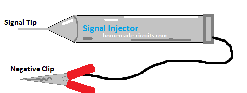
For this you can use a tubular probe which may have the intended oscillator circuit built-in.
For fault finding audio circuits you'd only need to inspect the doubtful areas with the switched ON probe and by touching the various nodes of the audio stage..
The design works with a tiny solitary dry cell, hence all of the elements could be accommodated within a cylindrical tube like housing.
The resistors should be as small as possible, possibly SMD type, while C1 and C2 may be rated at 6.3V again SMD type.
Make sure you use this signal injector for troubleshooting DC low voltage circuits only, and no AC mains directly operated circuits, which can be lethal to touch.
How to Troubleshoot an Amplifier using this Signal Injector
Testing can be done by working in reverse, from the loudspeaker end. Let's take the example of the following amplifier circuit under test.
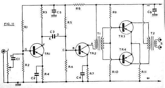
When the crocodile clip is hooked up with the negative supply line, while the prod placed on point A, the amplified signal may be audible from the speaker. This points out that the output stage is functioning correctly.
However if no signal is audible, inspections could be focused more around the output stage specifically.
Suppose the signal is heard on the speaker with the probe injected at point A. It could then be shifted to B, to inspect TR2.
At this point if the the signal shows decrease in its level, may indicate that this stage may be malfunctioning.
Make sure that tyou proceed methodically from the last stage towards the front stages, starting from the speaker.
When the stage where the problem is detected is crossed, you will find the signal level drastically diminishing on the speaker.
In the similar fashion as explained above you can proceed to test the other points as shown in the above example amplifier circuit.
4) Model Mini-Flasher
The muti-purpose multivibrator can be designed such that it operates with an extremely low frequency, with collector current that may be adequate to illuminate a bulb.
One particular application of this form of circuit is demonstrated in the following figure.
The objective of this design would be to replace a mechanical switch based toy lighthouse, toy car signal, or for any identical application in which a repeatedly pulsating light source is desired. By using a 6V LED lamp, current intake can be kept minimal.
Capacitors C1 and C2 are selected with substantial values, offering a repeated time interval of approximately 1 second on and 1 second off.
The circuit may work using supplies from 3V to 6V however a 6V lamp will probably be necessary for decent illumination of the bulb and attraction.
The working current is probably acquired from an existing battery already employed in the system to commute a motor or some other task.
5) Double lamp Blinker Circuit
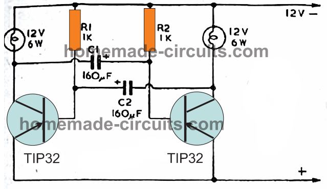
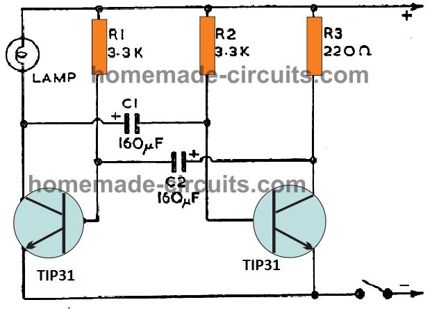
This double lamp flasher circuit as shown could be enclosed inside a robust housing to operate a set of two 12 volt 6 watt lamps, which then could be used in “accident" scenarios, by placing the unit on the roof of the wrecked car at night times.
Another application is generally to alert the speeding drivers while the driver change the wheel of his damaged car.
In this design, a couple of TIP32 transistors are applied, however other variants could be tried, provided they are appropriately rated for the lamp current.
With 12V 6W lamps, the collector currents can be approximately 500 mA.
The illumination of the lamps tend to be most distinctive when they are separated around 1 ft or more apart, possibly next to each other, or one over the other.
6) Metronome Circuit
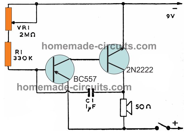
A metronome is an device which delivers periodical ticking or beating sound, and its function is to establish the proper tempo for any musical performance.
When employed in in this manner, it supplies a consistent beat to ensure that pace of the music is not changed by the musician in the course of training, and in addition it helps an accurate performing speed to be established.
When it comes to speedy and challenging bits, a performer may need to exercise to the appropriate pace.
A piece of audio might have the rate mentioned on it with respect to the amount of notes of specified duration per minute.
Or one of several audio terms articulating the right speed could be identified at the very top or start of the tunes.
These terminology include from slower, to faster speeds, and symbolize a specific quantity of beats per minute. The ones most typically demanded are given below:
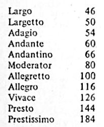
With the part numbers indicated in the diagram, it may be observed that it is possible to adjust the circuit from around 44 beats per minute, and 200. These might be measured through seconds.
As R1 value is decreased you will find an increase in the maximum range of the frequency.
Which in turn may be set through VR1 for minimum resistance. Likewise, increasing the values of the specified resistances brings about lowering of the periodic frequency.
7) Mini Piano Circuit
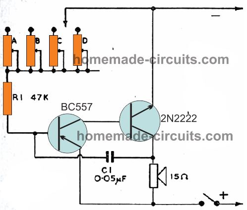
The Minano or mini-piano in fact generates an organ-like notes, that are rich in harmonics, and of pretty pleasing to hear. A musical instrument of this kind could prove to be a lot of fun.
It could possibly create just one tone during a period, which streamlines performing, since there isn't any chords involved or the need of striking several tunes at the same time frame.
The feedback through capacitor C1 across the collector of 2N2222 and base of BC547 is responsible for generating the osculations .
The value of the capacitor decides the frequency of the circuit, which can be changed as desired.
R1 value cannot be changed since it is supposed to be fixed with a minimum required value ensuring the highest frequency note.
To obtain lower frequencies or tunes, several adjustments in the form of A, B, C, D, presets are added in the design.
The frequency will decrease, as the resistance adjustment on the preset is increased.
A calibration of around 2 octaves, based on Middle C, would be quite fine, and will cover frequencies from 128 to 512 Hertz.
You will actually find an assortment of frequency ranges applicable, the popular ones are probably Standard and Concert Pitch.
For these ranges, the resistance value of 100K on the preset will usually be quite enough.
Keyboard
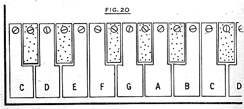
The diagram above depicts the keyboard for the mini piano having a little over one octave.
For practically implementation of the keyboard make sure the keys are at least 25 mm apart from each other, and without sharp edges.
8) Model Train Controller Circuit
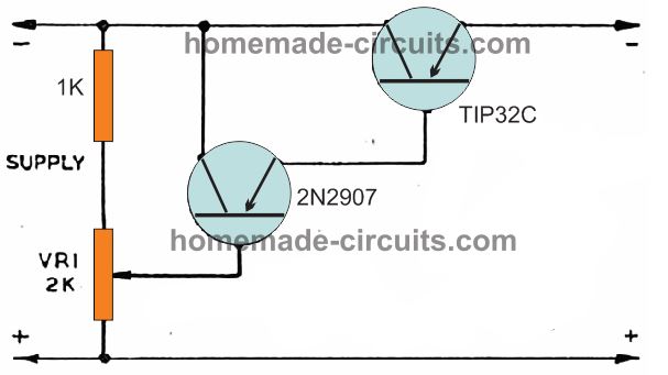
This circuit can be used for controlling supply voltage, and thus can be used for dimming DC light bulbs or for speed control such as in model trains.
The figure above displays the essential circuit, which will usually be sufficient for most model train control.
VR1 is attached across the DC supply line, and its adjustment makes it possible for any desired voltage to be set at the base of the first PNP 2N2907.
The two transistors are connected as Darlington pair in order to increase gain of the pair and to minimize the current load on VR1.
It ensures that the base current of the first PNP may simply not surpass 0.1mA, while that of the the second PNP TIP32 may be driven over 5mA. The O
The emitter voltage of this PNP BJT follows its varying base potential, in order that the second transistor's base voltage is controlled in exactly the same manner.
This results in an output that accurately follows the pot variation and replicates a varying output voltage across the collector of the TIP32.
Thus the pot setting determines the output voltage which can be varied from 0 to the supply level, with a drop of 1.2 V which is the standard biasing drop for the two PNPs combined.
9) Variable Power Supply Circuit
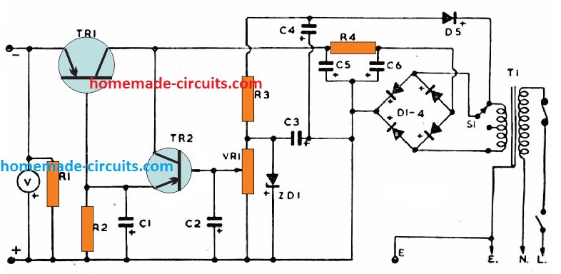
An extremely handy little power supply circuit featuring fully adjustable output voltage right from the lowest possible voltage can be seen above.
The transformer steps down the input mains AC to the required low voltage AC which is then rectified by the bridge rectifier into an equivalent DC.
The zener diode ZD1 provides the required regulation for the output. The biasing for this zener is acquired via D5, and the associated parts. C3 and C4 are positioned for filtering out the ripples.
VR1 works like a potential divider, which enables the user to apply the desired potential at the base of the TR2 transistor.
Since TR1 and TR2 are connected as emitter follower, any voltage that appears at the base of TR2 is replicated at the collector of TR1.
This means as VR1 is adjusted the TR1 output also adjusts the equivalent amount of voltage across the output terminals.
However, since the minimum emitter drop of a Darlington transistor is around 1.2V, the emitter output will always lag behind with this value of 1.2V and will show a drop at the output by a level of 1.2 V.
C1 and C2 act like electronic smoothing network and helps remove all sorts of interference and hum from the circuit.
Being a purely linear design, the TR1 may show significant amount of heating as the difference between the input and the output is increased.
Meaning if VR1 is adjusted to get 3 V at the output, and the input is 24V from the transformer, then TR1 may dissipate a huge amount of power to compensate the input/output difference.
The switch S1 is introduced to prevent this situation and help control the dissipation to a great extent.
Therefore while working with lower output adjustments, it is recommended to switch S1 to the center tap so the input/output differential is reduced by 50% which also reduces TR1 dissipation by 50%.
10) Simple Lie Detector Circuit
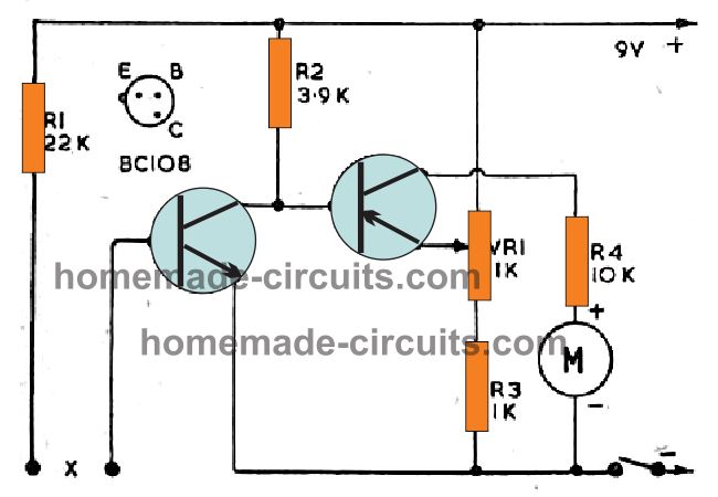
A lie detector gadget can be one that reveals any kind of change in our skin conductivity, hence the user with this lie detector is able to confirm whether or not a lie from the target who is in question.
This design is actually just for experimental purpose, and may not be too reliable for guaranteed results.
There are a couple of important factors behind this. One, using lie detection device is never considered a valid method by the law.
Second reason is, since the circuit depends on the moisture levels of the accused person's hand, this may sometimes give misleading results as the person may be actually innocent but due to psychological weakness may sweat heavily causing the meter to indicate a wrong lie detection.
The resistance at X, along with R1, effects in a certain magnitude of collector current for the first transistor stage.
This results in a drop in the potential across R2, and correspondingly affects the base potential of the second transistor stage also.
VR1 makes it possible for the emitter voltage of the PNP to be adjusted such that only the desired minimum amount of collector current passes through the meter.
A 1mA, FSD type moving coil meter can be used for this application. R4 ensures that current to the meter never exceeds beyond unsafe results under any circumstances.
With appropriate tweaking and setting the lie detector can be set up in such way that even a small amount of moisture across the test points may lead to noticeable deflections on the meter.
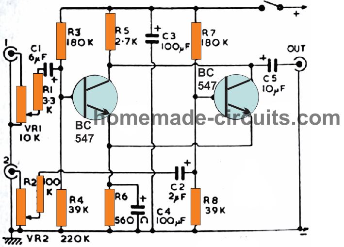
11) Lie Detector with Audio Output Circuit
This is another lie detector circuit which makes use of a headphone or a small speaker for processing the output results.
It's again a transistor astable circuit configured to generate a specific tone frequency on the connected speaker.
However since this frequency is directly determined by the RC elements at the base collector of the two transistors, it becomes possible to change the output tone by changing the base resistance of one of the transistors.
The skin resistance when placed between the points X converts the skin resistance into a varying tone on the headphone.
Higher skin resistance initiates the output to generate low frequency intermittent click-click pulses on the speaker headphone.
The frequency of this signal goes on increasing as the skin moisture increases, probably due to a lie spoken by the accused.
This allows the user to understand the level of truth spoken by the accused.
12) Automatic Mast Light
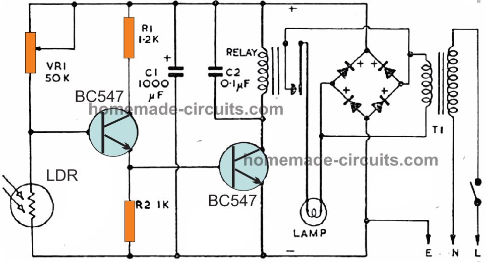
This simple automatic mast light circuit will automatically switch OFF a connected lamp everyday at dawn break, and switch it ON when night sets in.
The working principle is simple. The preset VR1 setting and the LDR resistance develops a potential at the base of the associated BC547.
VR1 is adjusted such that this potential is minimal while sufficient light is present on the LDR during daytime.
This in turn causes the voltage at the base of the other transistor to be significantly low so that it remains OFF and also keeps the relay and the lamp switched OFF.
When appropriate darkness falls, the LDR resistance increases causing the potentials at the bases of the two transistors to increase proportionately until they switch ON the relay and the lamp. The cycle repeats each day and night accordingly.
Here the lamp is a low voltage lamp used with the transformer low voltage AC, however an AC mains operated lamp could be also used by appropriately wiring the relay contacts and the lamp with the AC mains line.
Light Activated Lamp without Relay
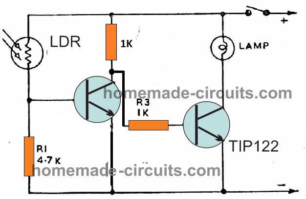
If you do not wish to include a relay and want to use a DC lamp or an LED lamp for the intended automatic day night lamp activation, in that case the following simple configuration could be tried.
The working process is similar to the previous circuit, except the relay which is replaced with the TIP122 transistor and the DC lamp or LED lamp.
13) Simple Intercom Circuit
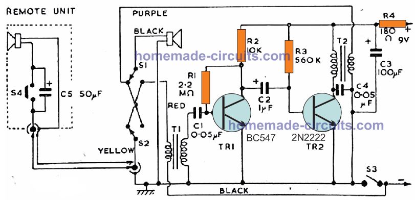
This intercom circuit delivers 2-way communication across selected locations or rooms, upstairs-to downstairs, or within home by a simple press of a push-button from either end. Additionally it is can be a fun telephone for school kids.
This circuit can be also useful as a baby-crying listening device.
The design basically consists of a main or master systems, along with a distant system, linked with a double wire extension lead. S1 and S2 are a DPDT push switch, which consists of contacts as shown in the normal situation.
Switch S3 is the master device on-off switch, and S4 works like the remote unit contacting switch. To make the working easier, S1/S2 are indicated by the prints “Press to Call or Talk”. S3 is marked “On", and S4 "Press to Call".
During the functioning, when the distant side user chooses to communicate, the person will press S4.
This connects the battery negative circuit via the transformer primary T1 so that it generates a feedback and activates an sound tone in the master speaker.
Next, the individual handling the master unit pushes the switch S3 to switch ON the intercom.
In this situation, anything spoken on the remote speaker gets amplified and becomes clearly audible over the master speaker.
To initiate an opposite communication, the individual at the master unit side activates the switches S1/S2, which causes his loudspeaker to work like a microphone.
The amplified voice is subsequently carried to the remote unit to complete the communication.
T1 and T2 are small audio transformers having a ratio of 1:5 meaning if the primary side 100 turns, the secondary side can be 500 turns. You can also try any small step down transformer.
14) Audio Mixer with Booster Circuit
If you are looking for a circuit that will mix two audio signals and produce a combined signal at the output then the above shown 2 transistor audio mixer circuit will probably do the job for you!
The circuit will not only mix and blend two audio signals but also boost them to a higher level so that it can be readily employed for feeding a power amplifier.
It features a pair of audio inputs, which are amplified by separate single transistor amplifiers configured common emitter amplifiers. VR1 and VR2 allow the user to select how much signal can be passed across the two inputs for appropriate mixing of the signals.
15) Pre-amplifier Circuit
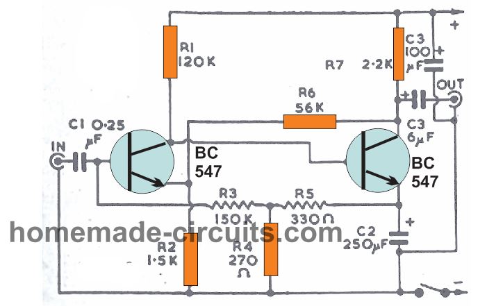
A simple yet very useful little pre-amplifier circuit can be built by wiring just a couple of transistors.
The unit will easily boost a 1mV signal up to 100mV or even higher. It is thus very handy for amplifying extremely small signals which cannot be used directly with a power amplifier.
This pre-amplifier offers a very high input impedance. This is often an essential aspect, while working with any high fidelity product.
The output offers low impedance, and can be compatible with almost all power amplifiers with good enough results.
The amplification achieved is determined by to a certain extent on genuine transistor selections, and also on the supply source level, however you can expect this to be approximately around 30dB.
We can see a pair of feedback loops in the design, one is using R3 and R5 attached to the first transistor base, while the other is implemented through R6 to emitter.
The indicated magnitudes are the recommended values, because they additionally fix the DC operating conditions for the two stages. A 250k potentiometer is used as the volume control at the input.
16) Impedance Buffer Circuit (Impedance Matching Stage)
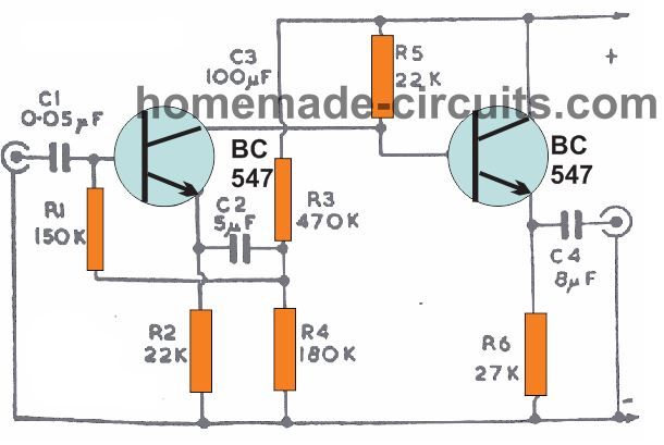
In audio circuits it often becomes important to integrate two stages which are incompatible or having different impedance levels. This may lead to substantial losses if connected directly without a buffers stage.
Earlier we used to have transformers for this purpose, but these have its own drawbacks. Transformers can attract hum and noise even after proper shielding. Moreover transformers can be bulky and expensive.
Another quick method of matching impedance is by adding a high value resistor. But this method can be highly inefficient as this would resist the actual signal, hampering the actual amplification process.
The 2 transistor buffer as shown above triumphs over this kind of complications. It features a high input impedance, but a low impedance output.
The gain of this buffer circuit is around unity or 1, meaning the output will be almost the same as input, even with an optimal impedance matching.
Needless to say , this circuit must be enclosed and attached to a metal box in order to achieve perfect screening from external stray pickups. If an AC to DC adapter is used make sure appropriate hum control is included to prevent hum related issue.
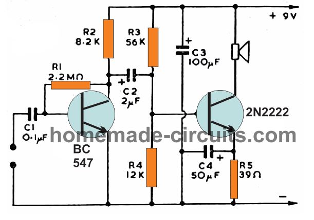
17) Power Amplifier Circuit
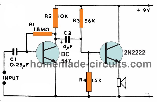
If you think that building a decent power amplifier using just two small transistors is impossible then you may be wrong.
Just a couple of standard small signal transistors are actually sufficient for making a reasonably loud power amplifier that may reproduce music loud enough to be be heard within a room comfortably.
As indicated in the diagram, the design incorporates two high-gain NPN transistors. Audio input is by means of C1.
The resistor R1 gives the base bias current for this stage, R2 works like the collector load. C2 connects signals across the output stage.
Base bias for the transistor at the output stage is established using the resistors R3 and R4.
This 2N2222 transistor functions being a grounded collector amplifier, wherein the collector is not really joined to the ground line, rather is grounded with respect to the audio signal variations and through the battery negative, that offers minimal impedance.
For general usage, a 15 ohm speaker can be quite reasonable, however it you may probably find that loud speakers of up to about 75 ohms may also work exceptionally well.
Current consumption will be approximately 25 to 30mA when a 15 ohm speaker is adopted, which may drop to 10 or 15mA with a 75 ohm speaker.
This small power amplifier using two transistors circuit may also generally be employed like a headphone amplifier.
Headphones as high as about 1.5k DC resistance may work extremely well, with current dropping to a mere 2 to 3mA.
The simple amplifier discussed above can be also used with the speaker attached to the collector side of the 2N2222.
This version may have slight better amplification level than the emitter side counterpart but the 2N2222 may show a slightly more dissipation and might require a heatsink for controlling the dissipation to safe limits.
18) Water Level Buzzer
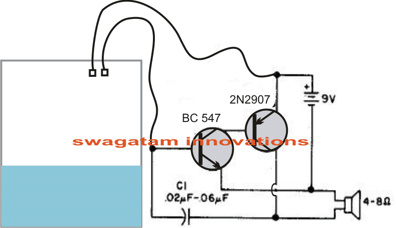
Just two transistors may be needed to make this simple audible water level indicator circuit. When the indicated probes come in contact with water, current flows to the base of the BC547 and triggers it ON. This in turn switches ON the PNP 2N2907.
Due to this a voltage surge is sent across the speaker.
The speaker being an inductive load responds with a negative spike to the base of BC547 which instantly switches it OFF hard via C1.
With BC547 switched OFF, the 2N2907 and the speaker is also switched OFF.
The situation reverts the circuit to its original status, and BC547 yet again gets a chance to switch ON, and the cycle repeats rapidly generating a sharp tone on the speaker.
19) Two Transistor Latch
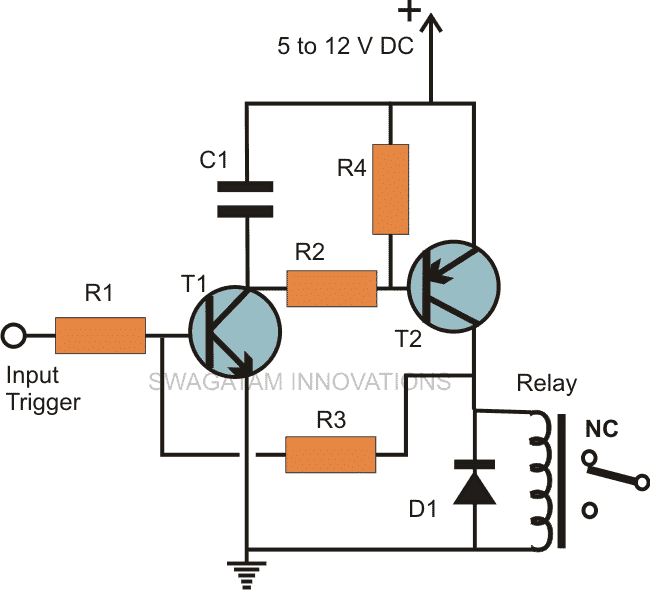
The mini latch circuit shown above using a couple of transistors can be very useful in applications that require latching of a relay in response to a momentary trigger.
Here, when a momentary positive trigger is applied at the input the transistors complement and conduct together along with the relay.
At the same time, a feedback voltage reaches via R3 to the base of T1, which latches the network and the relay permanently, even after the input trigger is removed.
R1 and R3 can be 100K, R2, R4 can be 10K, the transistor can be BC547 and BC557 for T1 and T2 respectively.
C1 must be a 10uF/25V, and preferably it must be positioned across the base/emitter of T1.
20) Small 2-Transistor Inverter
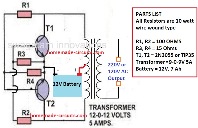
Inverters are recognized as high power units which mostly require sophisticated configurations and parts. However, surprisingly, a simple inverter with reasonably good power output can be built by configuring just a couple of power transistors as shown above.
The power output can be as high as 120 watts if the battery used is rated at 12 V 30 Ah, and the transformer is accurately rated at 10 amps.
21) Guitar Fuzz Circuit
This guitar fuzz circuit uses just a couple of transistors and it has been well tested out by several music artists and it has turned out extremely effective.
Transistors Q1 and Q2 are configured like a voltage amplifier containing ample gain for getting 'overdriven' with the help of a fairly reduced input, for instance an electric guitar.
By doing this the Q2 output becomes a 'Squared -Off' variation of the input, supplying the intended fuzz sound effect.
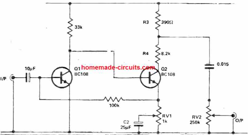
The pot RV1 modifies the level of negative feedback introduced into the circuit through C2, which results in the squaring of the signal. The role of resistors R3 and R4 is to minimize the output voltage to some appropriate degree, which can be subsequently tweaked as necessary with the aid of the volume control pot VR2.
22) Two Transistor Hum Remover Circuit
It is possible to eliminate hum sound from an audio signal significantly, simply by combining an antiphase hum of equivalent amount.
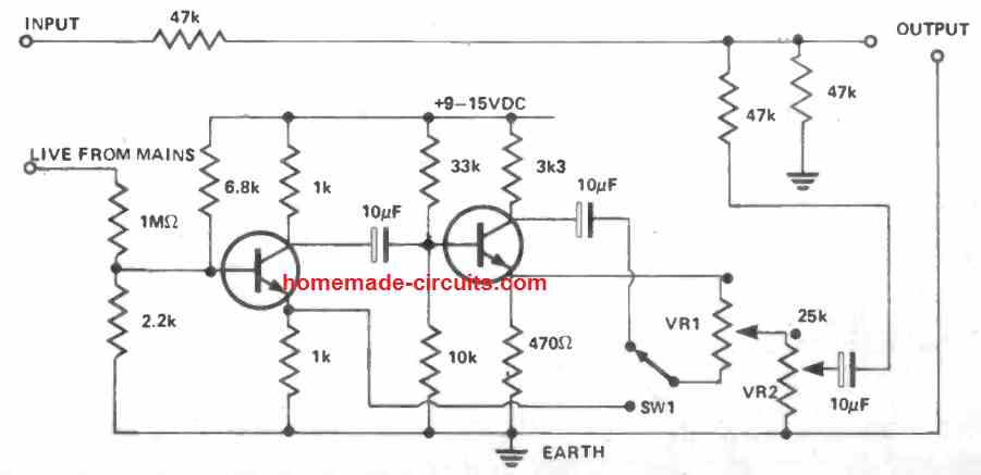
In the hum remover circuit shown above both the transistors could be inexpensive low or high gain varieties.
Preset VR1 can be tweaked, along with the preset VR2 to a low level, until you find the hum is almost gone.
You have then to switch the SW1 in the next step, where the VR2 is further adjusted until the hum is completely removed.
23) Darkness Detected Lamp Flasher Circuit
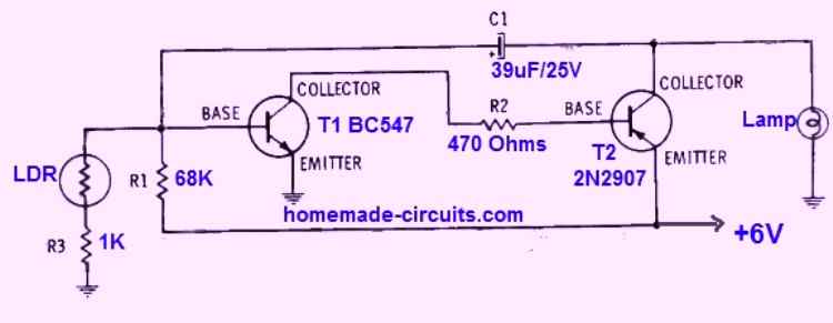
This circuit will start flashing a lamp when it detects a complete darkness.
As long as day light keeps the LDR illuminated, its resistance remains minimum.
Due to this minimum resistance the base of the transistor T1 remains grounded and disabled. With T1 disabled, the T2 is not able to get any base trigger and it also remains shut off.
Now, as soon as the light is removed from the LDR, or when darkness sets in, its resistance increases to many megaohms.
Due to the high resistance of the LDR, T1 base gets the required biasing pulse via the capacitor C1.
T1 now conducts forcing T2 to conduct.
When T2 conducts the lamp gets the required voltage for its illumination. In the process the conduction of T2 cause the base of T1 to be grounded via C1.
T1 now shuts off, so that T2 also shuts off, which causes the lamp to shut off. The process is forced to repeat.
The process causes the transistors to switch ON/OFF which in turn causes the lamp to flash.
The next day when the LDR is yet again illuminated through day light, the circuit is disabled and the lamp stops flashing until darkness is again detected.
Two-Transistor Morse Code Practice Oscillator
This circuit employs the well-known PNP-NPN two-transistor configuration to generate an oscillator operating within the mid-audio frequency range.
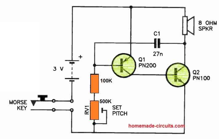
It is designed to drive either an 8 Ohm loudspeaker or, alternatively, low-impedance headphones.
By adjusting the potentiometer RV1, you can control the pitch of the oscillator. The Morse code key is integrated into the battery circuit, allowing you to simply turn the oscillator on and off.
To operate this oscillator effectively, you only need a 3 V battery, which provides sufficient volume for practice.
However, if you wish to use a power supply with a voltage rating of up to 9 V, please be aware that the output can become quite loud.
If the sound is excessively loud at 3 V, you can reduce the volume by adding a low-value resistor (ranging from 22 to 100 Ohms) in series with the speaker.
Hope you Liked Them
So these were a few two transistor circuits which can be used for various useful circuit applications and products.
Transistors may look tiny, vulnerable, and somewhat insignificant when they are alone, but as they are combined they together grow into formidable designs capable of accomplishing huge tasks.
Even just a pair of these are able to combine and enable the user to achieve interesting circuits with huge potentials and versatility.
If you have more clues regarding how to use two transistors for creating something new, the comment box is waiting for your valuable inputs.


Questions & Answers
Thank you Mr. Swagatam for imparting technology into those of us who love Technology.
I went through some of your projects here and picked interest in one 2 way intercom with remote. It’s circuit diagram is made up of two small audio transformers. Any design with Transformer nowadays are very hard to get in my own area and for this reason they are no longer seen in our markets.
Can you please do me a favor:
(1) by sending to me the one that has Transistors in place of the said Audio transformers or
(2) ICs in place of the audio transformers. Thank you.
Thank you Ugwe,
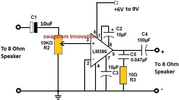
Please try the following circuit and check whether the amplifier is able to amplify the voice signals spoken near the left side speaker.
When you speak near the left speaker, it should be amplified at the right side speaker.
Try this, if it works then we can modify it into an intercom by connecting switches.
Hi Adam. My name is Elliott Bartlett. I read your article on turning any light into a strobe light. I have a 24v car head light I have attached to a riot shield for playing Airsoft ( similar to paintball ). I am looking for a way to creat a switch to give the light a wicked strobe effect. Are there any YouTube videos you have that could help me out, I’m a visual learner and new to circuitry but pretty handy and mechanically inclined. Thanks.
Hi, do you want the car headlight to strobe as soon as it is hit by the bullet?
Sorry I do not have any related Youtube videos on this.
If you can provide the specifications in detail, I may try to help!
And basically I would
Like them to have a disorienting effect on my Oppenents. So a high speed constant strobe.
Thanks , do you know a website where I can get the circuit parts now ?
No problem!
You can buy the parts from amazon.
Ok so I need a circuit board, I’m guessing the .01uf is a capacitor I saw that on Amazon, as well I saw the 47uF, I saw the 100k preset and Amazon pulled up a potentiometer. The 1k and 47k are those ohm resistors ? Not sure what the numbers on the circuit board represent ( possible slots ? ) and the tip 31 not sure what that part is either. Any further tips you can give me ? Forgive me but all of this is a foreign language to me but I’ll pick up on it hopefully rather quickly.
All the resistors with “k” are “k ohms” rated at 1/4 watt, and 5% CFR, although these ratings are not critical.
You can use a 100k pot if you want the control to adjustable externally.
TIP31 is a transistor.
Please try the image link of Google to get a clear idea of all these parts.
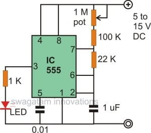
OK, here’s one strobe light circuit that you can try for your application:
That’s a cool thought to strobe when it gets hit… but I have 2 car lights that run off anywhere from a 12 v-24v battery. They are 24000 lumens each so pretty bright.
The description is NAOEVO 7inch LED Light Bar, 240W 24,000LM Offroad Fog Light Driving Lights LED Pods with Spot Flood Combo Beam, Waterproof Led Work Lights for UTV ATV Jeep Truck Boat, 2 Pack
In regards to #1 above, here’s a version which has some neat features:
1) It puts out voltage on two legs, each leg alternates.
2) It has zener diode protection for the transistor bases to prevent excessive negative voltage damaging them.
3) It always starts building voltage on one particular leg. Usually, an oscillator of this type will build voltage on whichever leg’s transistor turns off first, so which legs builds voltage first is generally random. This iteration of this oscillator is used to drive a positive- and negative-voltage charge pump, and there’s no need to drain voltage off the charge pump capacitors before they’ve been charged in the first place, so it always starts on the leg which charges up the charge pump caps. It’s done by using two small caps to hold one transistor base high and one low as the circuit starts up. The active diode (ie: transistor) in series with each capacitor means after the first couple cycles, those capacitors do nothing and have no effect upon the circuit.
4) The outputs are buffered via MOSFETs.
5) It uses an NPN and PNP transistor pair base-to-base, with a potentiometer between the bases, as a current limiter. The PNP transistor puts voltage onto its base, the NPN transistor takes voltage from its base, so the two transistors equally carry the current they each pass from collector-to-emitter. The potentiometer makes it a variable current limiter.
6) It uses active diodes (ie: transistors), rather than regular diodes. Active diodes have much less back-leakage.
7) It provides the perfect positive and negative voltages to drive MOSFETs with a maximum gate voltage of +- 20 V.
8) The large (250 nF) caps on the output provide a low-impedance source of voltage to quickly switch a MOSFET.
This is part of a larger circuit, an H-bridge for a motionless electrical generator I’m developing, with adjustable turn-on and turn-off times for the MOSFETs to prevent shoot-through, and realistic H-bridge MOSFET Gate-to-Drain, Gate-to-Source and Drain-to-Source capacitances and resistances, and additional cascode shoot-through protection.
Here’s the circuit simulator with just the oscillator, current limiter and charge pump:
http://tinyurl.com/y5wjk7q3
And here’s half the H-bridge mentioned above:
http://tinyurl.com/yyh6jf5h
If you want to realistically model a MOSFET in a circuit simulator, you have to check its datasheet and do some calculations. Here’s the data for the MOSFETs I’m modeling:
sup70101el
———-
Ciss = 7000 pF
Coss = 2180 pF
Crss = 170 pF
Reverse transfer capacitance (Crss) = Cgd
Cgd = 170 pF
Output Capacitance (Coss) = Cds + Cgd
2180 pF = Cds + 170 pF
Cds = 2010 pF
Input Capacitance (Ciss) = Cgd + Cgs
7000 pF = 170 pF + Cgs
Cgs = 6830 pF
———-
sup70090e
———-
Ciss = 1950 pF
Coss = 845 pF
Crss = 54 pF
Reverse transfer capacitance (Crss) = Cgd
Cgd = 54 pF
Output Capacitance (Coss) = Cds + Cgd
845 pF = Cds + Cgd
Cds = 791 pF
Input Capacitance (Ciss) = Cgd + Cgs
1950 pF = 54 pF + Cgs
Cgs = 1896 pF
———-
I was wondering how to apply the two transistor idea to measuring water level? To avoid corrosion on the electrodes they would need to have alternating polarity applied to them with reference to ground.
Do you have some ideas how this could be done?
Thanks, Martin
You can probably achieve this by replacing the 9V DC with 9V AC and insert 1N4007 diodes in series wit the emitter leads of the two transistors
Very good!! Thanks for demonstrating with a variety of examples. These are very good examples of using two transistors circuits. Sometimes it is good to get back to simplicity and to the basics of building circuits using discreet components with quite useful and practical designs.
Keep it up.
Thanks, Martin
Glad you liked it Martin, appreciate your feedback
Hi friend!
A good quest,
nice…
Greetings
Thank you friend!