The LED AC mains voltage level indicator is a circuit that can be used for displaying and monitoring the instantaneous voltage level of any 220 V or 120 V mains home AC input, through a correspondingly rising and falling LED bar graph.
A simple construction and accurate result are the main features of this tiny AC voltage monitor circuit. Learn how to make ac voltage indicator from led in a most simple and easy to understand method.
Why Monitor AC Mains Voltage Level
The AC mains line that we get in our household electric socket outlets, may at times be full of dangerous fluctuations. These may either be in the form of a sudden high voltage or a low voltage.
Both the situations can be very “fatal” to our sophisticated electronic equipment like TVs, DVD players, refrigerators, computers etc to name a few.
A simple electronic part such as an LED can play an important role in displaying and monitoring the condition of this AC mains voltage and warn us of a possible electrical hazard. Here, I have explained exactly how to make ac voltage indicator using leds through a construction of a little electronic circuit.
How to Construct the LED AC Voltage Indicator
It is completed through the following few easy steps:
In the procured general purpose board, with the help of the circuit schematic start inserting the transistors first in a straight line and solder their leads.
Similarly insert and solder the resistors, zener diodes, LEDs, capacitors, presets etc. in an organized manner and solder them with reference to the circuit diagram.
How to Test the Circuit?
The following testing details will furthermore help you to understand exactly how to make ac voltage indicator using LEDs:
For testing the completed circuit board you will require a transformer with multiple voltage outputs.
Connect the transformer to the AC mains; also connect the common secondary output of the transformer to the negative point of the circuit. Make an alligator clip/ wire assembly.
Solder the wire end of the clip to 1N4007 diode input.
Now attach the clip to the 3 volt output of the transformer, adjust P1 so that the first LED just starts glowing.
As above, go on connecting the clip to 6, 7.5, 9 and 12 volts of the transformer and adjust the presets P2, P3, P4 andP5 so that the relevant LEDs just start to glow at the respective voltages. This completes the testing and the setting of the circuit.
Finally join the 6 volt transformer to the circuit and switch ON the power. You will find that LED 1, 2 and 3 are glowing brightly,
LED no.4 is glowing with less brightness while the last LED is completely OFF, indicating a safe level of AC mains voltage.
Now in case the voltage exceeds a high level (above 260 volts) the last LED will start glowing brightly indicating a dangerous situation.
If the voltage drops to a dangerous level (below 160 V) LED 3 and may be LED 2 may cease to glow, again indicating a bad low voltage.
Parts Required
- You will need the following mentioned parts for the project:
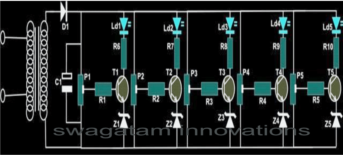
- TRANSISTORS T1, 2, 3, 4, 5 = BC547
- ZENER DIODE Z1----Z5 = 3 VOLTS / 400mW
- RESISTORS R 1—R10 = 1 K ¼ WATT, CFR.
- CAPACITOR C1 = 1000uF/25v,
- DIODE D1 = 1N4007
- LED 1, 2, 3, 4, 5 = RED 5mm DIFFUSED
- PRESET P1, 2, 3, 4, 5 = 47K LINEAR
- GENERAL PURPOSE BOARD = 6” x 2”
- TRANSFORMER = O – 6 VOLTS/ 500mA
Mains Voltage Monitor Circuit using LM358 IC
Knowing if the AC voltage level is on the low side by just looking is beneficial especially if you’re about to operate a computer.
But there is a hazard to this. Once the mains is already low, additional loads may force the AC voltage to plummet further beyond safety levels.
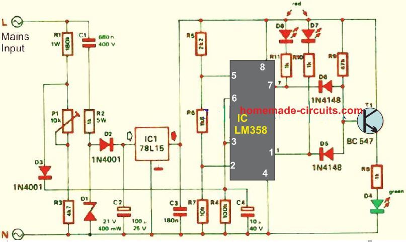
The supply for the current circuit is provided directly from the mains which happen across R1 and P1.
Two reference voltages are given by the 15 V steady-state voltage generated by R2, C1, C2, D1 and D2.
Using a preset reference level of the mains voltage, these two voltages are compared in A1 and A2 from the IC LM358. If the subsequent mains become less than 210 V, D7 will illuminate. When the reading is more than 250 V, the light on D8 will be switched on.
If neither of them lights up, T1 turns on and allows D4 to be lit. This only means the mains voltage is in the safe operating limits.
How to Set Up
Preset P1 sets the AC voltage limit with help from the multimeter and a variac. You don’t need to strive for accuracy as any value around the centre of its travel is acceptable.
The circuit in the discussion is not isolated from the mains but must. We strongly urge you to verify that separated fiber case is always used to isolate this circuit from the mains before switching on.
Using LM324 IC
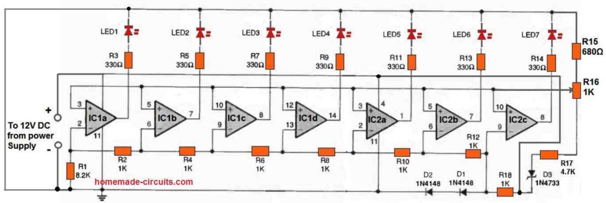
The design for the AC Line-Voltage Monitor circuit is shown in the above figure. The circuit, as previously noted, is powered by a wall transformer rated at 12 volts DC.
Two quad LM324 op-amp ICs (IC1 and IC2) are the heart of the circuit, and they are powered by regulated power from a fixed DC supply that is supplied by a 5.1-volt Zener diode, D3. The IC LM324 Op-amps power an LED bargraph using the LEDs 1 to LED 7.
The slider arm of potentiometer R16 supplies the op-amps with a programmable reference voltage.
The voltage divider made up of resistors R1, R2, R4, R6, R8, R10, R12, and R18 provides the input voltage.
These resistor values were selected such that when the AC line voltage, or a tenth of it, fluctuates from 100 to 132 volts, the op-amp outputs switch on consecutively and illuminate the LEDs.
The LED bargraph's midway is typically set by potentiometer R16 at 118 volts, however this value can be changed as desired.


Questions & Answers
I need led showing directional indicator power flow in ac power solar cell.
Sorry, not sure about it…can’t figure out the idea.
When you use DC clamp amp meter on a dc wire. it can display – sign if current in or out.
thanks a lot.
I understand that.but what I mean is, to make the AC line automatically switching off from the appliance as soon as it detected the unsafe zone.
greetings.
OK, in that case one can try the following circuit
https://www.homemade-circuits.com/2011/12/simple-mains-ac-over-voltage-and-under.html
Good after noone Sir!
Is it not good idia to develope this circuit in order to use more of it?I mean,as soon as voltage exceeds 260v and drops blew 160v,the AC line go to the "off" position.Is that not helpfull for the needy people who can not afford to buy voltage stabilizer?
God bless you more and more for your nice work!
thanks, below 160V and over 260V are unsafe zones so as soon as this is detected, the user can simply switch OFF the mains….so the above circuit definitely can be useful if used sensibly