In this post I have explained regarding the basics of capacitor, and also regarding the various types of capacitors which are commonly available in the market and used in most electronic circuits.
Overview
A capacitor is simply a passive electronic part which is designed to store an electric charge.
In physical form, it is made of a pair of metal plates or electrodes separated by an insulation content or dielectric. Applying a dc voltage across the capacitor terminals instantly generates a scarcity of electrons on the positive plate and overabundance of electrons on the negative plate, as demonstrated in the following figure.
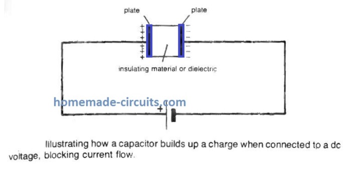
This differential build up of electrons gives rise to an electric charge, that accumulates a specific level (based on the voltage) after which stays at that level. If a dc is involved, the insulator inside the capacitor works like a blocking system for the flow of current (however might be a slight transient charging current that prevents when the capacitor is completely charged).
When ac is used across the capacitor the charge accumulated throughout half ac cycle gets reversed with the next 2nd half cycle, which causes the capacitor to allow the current through it to run efficiently, as though the dielectric insulation never existed.
Therefore when ac is involved, a capacitor simply works like a coupling device. You will find hardly any electronic circuits carrying ac and not incorporating a few capacitors, possibly for coupling or for optimizing the general frequency response of the system.
In the last mentioned scenario, a capacitor is connected with a resistor to create an RC combination. The charge/discharge occurrence involved with capacitors could also be used in various other circuits e.g. , the photographic electronic flash.
Just like resistors, capacitors could be configured work with fixed values or be adjustable in their magnitude. Fixed capacitors happen to be the primary foundations of a circuit (along with resistors). Variable capacitors mostly are intended for optimizing tuned circuits.
The performance parameters of every capacitor are different and thus their applications also differ accordingly.
One of the electronic components’ forms which is used widely is the electronic capacitors. Apart from this, the other capacitors used in the industry include ceramic, silver mica, electrolytic, plastic, tantalum, and others.
Each type of the capacitor is used in various applications according to their respective disadvantages and advantages.
It is quintessential that the right type of capacitor must be selected as the circuit in which the capacitor is used is greatly by the capacitor.
Thus, in case a correct type of capacitor is not selected to insert in the circuit on the basis of its parameters, it can result in the improper or faulty functioning of the circuit.
Basics of the capacitors
The physical laws which basically govern the various types of capacitors are same and are adhered to accordingly.
These basic laws determine various parameters of the capacitors such as how the capacitor would operate, the value of the capacitor, and its capacitance (the maximum amount of charge which the capacitor will hold).
Thus, the basic theory on which capacitors are built and work enables to understand the different capacitors forms and how these can be or are used.
Note: Even though there have been numerous developments in the field of dielectrics, the basic laws on which the capacitors work has not changed and they apply to date.
Types of Capacitors and Dielectrics
As discussed above, although the basic laws on which the capacitors work, the properties of the capacitors differ enormously because of the manner in which each type of the capacitor is constructed.
The various properties which various types of capacitors possess is given by their main element which is located between the two plates of the capacitor and is known as “dielectric”.
The dielectric constant of the capacitor can impact the capacitance level which the capacitor can achieve at a given specific volume. Also, various capacitors of different types can be found to be polarized in nature wherein the voltage running across the capacitor is tolerated in one single direction only.
On the other hand, various capacitors of different types can be found to be non-polarized in nature wherein the voltage running across the capacitor is tolerated in both the direction.
The capacitors are commonly named on the basis of the nature of the dielectric which is present in the capacitor.
This is indicative of the general properties which the capacitor will be exhibiting along with the various different types of circuit functions where they can be used.
Overview of capacitors and its different types
Different forms of design are employed for nonpolarized capacitors, nearly all of which are easily recognized from the style of the capacitor. You don't need to to look into fine detail regarding the real constructions. Their particular features are crucial, although, since these can decide the ideal variety to work with for a specific application.
Non-Polarized Capacitors
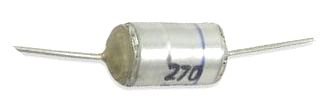
- Paper dielectric capacitors, typically identifiable through their tubular shape, are the cheapest yet typically bulky. Their many other key limitation is they aren't well suited for use at high frequencies over 1 MHz, which practically confines their application to audio circuits. These are usually found in values from 0.05 µF up to 1 or 2µF, having operating voltages between 200 to 1,000 volts. Plastic coated paper dielectric capacitors could have a lot larger operating voltages.
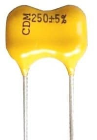
- Ceramic capacitors are very popular in small audio and rf circuits. These are pretty cheap and they are obtainable in a variety of values from 1 pF to 1 µF with substantial operating voltages, and in addition recognized by very low leakage. They may be manufactured in both discs and cylindrical structures and as metallized ceramic plates.
- Silver-mica capacitors are costlier than ceramic capacitors but they have outstanding high-frequency working capability and very much smaller tolerances, so are usually considered to be well suited for vital applications. They could be manufactured with extremely high operating voltages.
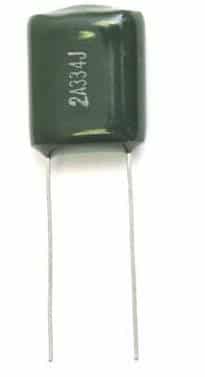
- Polystyrene capacitors are created from metallic foil separated with a polystyrene film, normally having a integrated polystyrene cover to guarantee an enhanced insulation property. These are known for their minimal losses with high frequencies, excellent stability and consistency. Values could vary from 10 pF to 100,000 pF, however working voltage typically comes down significantly with rising capacitance values.
- Polycarbonate capacitors tend to be typically manufactured in the form of rectangular pieces having end terminating as wires which can be easily inserted into PCB holes. They provide high values (as much as 1µF) in tiny dimensions, along with the features of reduced losses and minimal inductance. Just like polystyrene capacitors, operating voltages become compromized with higher capacitance values.
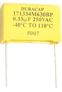
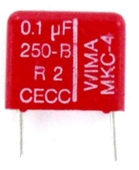
- Polyester film capacitors are likewise manufactured for direct assembly in printed circuit boards, having values from 0.01 µF up to 2.2 µF. These are usually bigger in size compared to polycarbonate capacitors. Their small inner inductance allows them to be specifically well suited for coupling and decoupling functions in electronic circuits. Values of polyester film capacitors are usually mentioned with a color code comprising 5 color rings.
- Mylar film capacitors could be considered to be a standard film type capacitor, commonly found in values from 0.001 µF up to 0.22µF, having a operating voltage up to 100 volts dc.
The various types of capacitors which are being used in most electronic circuits are as follows:
Ceramic Capacitor:
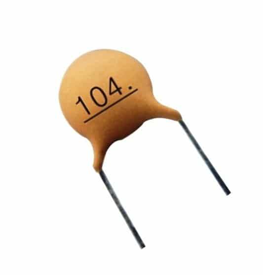
The capacitor namely, ceramic capacitor is used for multiple applications including RF and audio.
The range of the values of the ceramic capacitor is between few picofarads and 0.1 microfarads. The ceramic capacitors are the most widely used in the industry since it the most reliable and cheap type of capacitor available.
Also, another reason for its common and wide usage is that the loss factor of the ceramic capacitor is very low. But the loss factor of the capacitor is also dependent on the dielectric which is used in the capacitor.
The ceramic capacitors are used in both the formats of surface mount and leaded because of the constructional properties of the capacitors.
Electrolytic Capacitor:
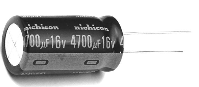
One type of capacitor which is polarized in nature is electrolytic capacitors.
The capacitance values which are offered by the electrolytic capacitor is very high which ranges more than 1µF. the electrolytic capacitors are used in the industry commonly for the applications which are conducted on low frequency such as decoupling applications, power supplies, and applications of audio coupling.
This is because these applications have the frequency limit of nearly 100 kHz.
Tantalum Capacitor:
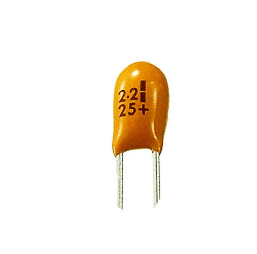
Another type of capacitor which is polarized in nature is tantalum capacitor. The capacitance level provided by the tantalum capacitor at their volume is very high.
One of the drawbacks of the tantalum capacitor is that there is no tolerance in the tantalum capacitor towards reverse biasing which can result in the explosion of the capacitor when exposed to stress.
Another drawback is that it has very low tolerance to the ripple currents and thus they should not be exposed to high voltages (such as voltages which is higher than their working voltage) and high ripple current. The tantalum capacitors are available in both the formats of surface mount and leaded.
Silver Mica Capacitor:
Although the usage of the silver mica capacitors have decreased significantly in the current era, the stability provided by the silver mica capacitors are still very high along with providing high accuracy and low loss.
Also, there is sufficient space available in the silver mica capacitors. The applications where they are primarily used include the RF applications.
The maximum values to which the silver mica capacitor is limited to is approximately 100pF.
Polystyrene Film Capacitor:
The polystyrene film capacitors provide capacitor of close tolerance wherever required. Also, these capacitors are relatively cheaper than that of other capacitors.
The dielectric sandwich or the plates present in the polystyrene film capacitors are rolled together which results in the shape of the capacitor in tubular form.
The placement of the dielectric sandwich and shape of the capacitor limits the response of the capacitor to high frequencies due to addition of inductance and thus responds to only few 100kHz.
The general availability of the polystyrene film capacitors is in the form of leaded electronics components.
Polyester Film Capacitor:
The tolerance provided by the polyester film capacitor is very low and thereby these capacitors are used in situations when the prior consideration is the cost.
The tolerance level of a large percentage of the polyester film capacitors available is either 10% or 5% and this is considered as sufficient for a range of applications.
The general availability of the polyester film capacitors is in the form of leaded electronics components.
Metallized Polyester Film Capacitor
The metallized polyester film type of capacitors consists of polyester films which are metallized and in every other sense, it is similar to the polyester film capacitors or another form of it.
One of the advantages which is achieved by metallic polyester film is that it makes the electrodes of very small width and thereby enabling the encasement of the capacitor in a package of very small sizes as well.
The general availability of the metallized polyester film capacitors is in the form of leaded electronics components.
Polycarbonate capacitor:
The applications where the most critical and crucial requirement is high performance and reliability, these applications use the polycarbonate capacitors.
The capacitance value is held over a long period of time by the polycarbonate capacitors since their tolerance level is very high. Such high tolerance levels are achieved because of the stability of the polycarbonate film used in the polycarbonate capacitor.
Additionally, the dissipation factor of the polycarbonate capacitor is very low and they can withstand temperature of wide range and remain stable.
The range of temperature which this capacitor can withstand is between -55ºC and +125ºC. In spite of all these properties, the manufacturing and production of the polycarbonate capacitors has significantly decreased.
PPC or Polypropylene Capacitor:
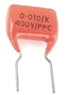
In this types of capacitors, the tolerance level required is higher than what the polyester capacitor can provide, then the polypropylene capacitors are used in these cases.
The material used for the dielectric in the polypropylene capacitor is a polypropylene film.
The advantage which the polypropylene capacitor has over the other capacitors is that it can withstand very high voltage across a time period and thereby the change in the capacitance level due to the increase and decrease of voltage over a time period is very low.
The polypropylene capacitor is also used in cases where the frequency being used is very low, mostly in the range of 100kHz being the maximum limit.
The general availability of the polypropylene capacitor is in the form of leaded electronics components.
Glass Capacitors:
The dielectric which is used in the glass capacitor is made up of glass. Even though the glass capacitors are expensive, their performance levels are very high.
The RF current capability of the glass capacitors is very high along with the loss being extremely low. Additionally, there is absence of any piezo-electric noise in the glass capacitors.
All these and some additional properties of the glass capacitors make them most appropriate and ideal for RF applications which require high performance.
Supercapacitor:
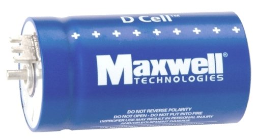
The other names by which the supercap is known are ultracapacitor or supercapacitor.
The capacitance values of these capacitors are very large as such is their name. The capacitance levels of the ultracapacitor go nearly towards many thousand Farads.
The ultracapacitor is used in the industry for providing a supply of memory hold-up along with various uses within the realm of automotive applications. The different major types of the capacitors are included under the supercap.
Along with them, there are various other capacitor types of capacitors which are used when the applications are specialized in nature.
The identification of the capacitors is majorly done through their parameters such as values which are marked over the cases of the capacitors. In order to display the parameters in a manner which is compact, the markings of the parameters are done in the form of a code.
VARIABLE CAPACITORS
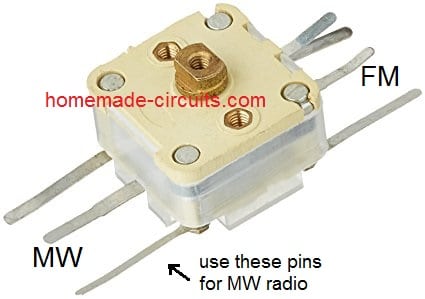
Variable capacitors are built with alternate pieces of metal plates, a single set being fixed and non movable and the other movable.
The plates are segregated with a dielectric which can be air or a solid dielectric. Motion of a single set of plates shifts the overall section of the plates, thereby altering the capacitance across the plates.
Additionally, standard differentiation between tuning capacitors utilized for repeated manipulation (e.g., to adjust a radio receiver station) and trimmer capacitors intended for preliminary setting up of a tuned circuit.
Tuning capacitors tend to be bigger, more powerful in structure and usually of air dielectric type.
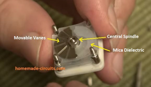
Trimmer capacitors are often determined by a mica or film dielectric having a reduced quantity of plates, where capacitance is tweaked by rotating a middle bolt to alter the strain across plates and dielectric mica.
Due to the fact these are more compact in size, even so, a trimmer capacitor might at times be applied like a tuning capacitor on a pocket sized FM radio circuit, although exclusive mini tuning capacitors are manufactured to install rightaway on a PCB.
When it comes to tuning capacitors, the structure of the vanes tells the way in which capacitance varies as the spindle is moved.
All these attributes generally are categorized in one of the following descriptions:
1. Linear: where each spindle rotation degree generates a similar alteration in capacitance. This is the most typical kind selected for radio receivers.
2. Logarithmic: where each degree of spindle movement generates a consistently varying level of frequency of a tuned circuit.
3. Even frequency: where every single spindle movement degree delivers the same variation in frequency in the tuned circuit. 4. Square law: in which the variation in the capacitance is proportionate to the square of the angle of spindle movement.


Questions & Answers
Hi Mr. Swagatam,
I had successfuly tested the 1000W 110V AC cooking appliance with the 220V AC input by initially using the 150uF capacitor upon your confirmation. But this time I will try it with the 170uF as you advised. However it seems that it is hard to find single 170uF, so I will have to use about 4 pcs of the various capacitors as the parallel connected
ie. 50+50+50+20=170uF. Or is it possible to use 4×50 =200uF or the 200uF is the beyond of the limitation? Or is it possible to use less than 170uF for instant 165uF? Briefly please advise the toleration if there is.
Thanks Suat, that sounds great!
You can use any combination of series parallel PPC capacitors to accomplish the 170uF value, however it should not exceed 170uF, otherwise the sole purpose of the capacitor will be defeated. The purpose of the capacitor is to limit the current to below 8.5 amps.
I would rather recommend using a 165 uF capacitor.
Hi Mr. Swagatam;
Mostly the polarized capacitors are being used after the bridge rectifiers.
If input is AC 220V and we use non-polarized capacitor after the bridge rectifier diodes then what kind of outcome we would meet?
Hi Suat, there will no difference in the rectified DC quality whether a polarized capacitor is used or a non-polar capacitor is used. Both will filter equally well, but non-polar capacitors may work better since they have lower leakage compared to electrolytic capacitors.
Hello Mr. Swagatam;
My battery charger has SF16A06 (super fast recovery rectifier) at its dc side and there is a ceramic capacitor 471 2KV before it.
This capacitor gets overheating and multimeter shows its value as 600 pF. It is possible to use polyester film capacitor instead.
Hi Suat, yes, you can replace the ceramic capacitor with a polyester film capacitor, to improve its performance….
Hi Swagatam;
My circuit source voltage is DC 5 V. And its IC is used to sending 5 V for the 1 second period over the 10 K resistor to the capacitor to be measured. The followings are the some data after the test results.(readings from the analog digital converter pin of 16f877a)
100 uF accumulates about 1,97 V (after 5 V charged for 1 second)
220 uF accumulates about 1,44 V
680 uF accumulates about 1,22 V
100 uF accumulates about 0,46 V
The aboves show that the lower capacitor capacity then the higher voltage inside or vice versa.
If it is possible to formulize the above data then it will be easy for me to write the program for measuring the capacitors. At the point I need your favour if possible. Regards
P.S.: ADC step voltage sensivity is about 0,0048 V.
Hi Suat,
If you charge a 100uF with 5V DC then it should store at least 3 to 4 V in it in 1 second. 1 second is is a long time.
Sorry, I can’t figure out the situation so I am finding it difficult to suggest a proper formula for this.
I understand that the situation seems weird. But please let me explain: I need to connect a resistor from (-) pole / voltage to the ADC pin of the 16F877A otherwise this pin perceives that as if there is always a (+) voltage. And also there are some other resistors used in the circuit to balance the sensitivity. So there is lower voltage stored than it should be. There is no problem to store the 4 or 5 V in the 100 uF capacitors. I can change the resistor values and make it increase the storage voltage but the ratio will not be changed. For instant if it would be the 4 volt inside the 100 uF then 680 uF would had been stored 2,47 V.
Best Regards
P.S.: Amendment ; in my previous message considering the last data : that would be the 1000 uF instead of 100 uF accumulates the 0,46 V
What you are saying makes sense, but I still cannot figure out a suitable formula, looks difficult for me. Let me know if you are able to solve this issue soon.
Hi!
I wonder how that 6 pins of the variable capacitor work in real circuit? Could you give practical extra thing about it?
Thanks for your tremendous efforts Swagatam.
Hi, 3 pins on one side are for MW station and 3 pins on the other side is for FM station.
The center pin is connected with the ground, and the outer two pins are configured with the radio coils for forming adjustable LC networks
Hi Swagatam;
If We have two sources that one transformer is DC 12 V 2 A and other is DC 12 V 0.5 A. and we will charge the capacitor as 6800 mF. When we try the above transformers to charge it. The charging period time will be the same or not regardless of the transformers ampere capacity.
Best Regards
Hi Suat,
According to y understanding, the charging period will be the same for both the sources, because the charging speed depends on the voltage, not the current.
Hi Swagatam;
I have 2 capacitors in my stock. The dimension of the first one is dia. 25 mm length 50 mm and this one is electrolytic type. And the dimension of the other one is dia. 45 mm lenght 95 mm. I assume that the value of both capacitors are same let’s say 100 mF 400 V. Please advise if it is possible to use first one instead of second one? In other word they do the same duty or not?
Best Regards
Hi Suat,
Only two things matter: the value of the capacitor and its type whether electrolytic or polystrene. The dimensions do not matter. If the values are same then they can be easily interchanged. However, an electrolytic may not work for a PPC. On the other hand a PPC can be used in place of an electrolytic.
Thanks for the above info.
I see some battery desulfator circuits with the parts of 1 pc bigger volume capacitor (like starter capacitor bigger than ordinary electrolytic capacitor) and 1 pc bridge rectifier and 220 V AC applied to the circuit. In the other word low current and high voltage charging method.
I think you are used to not advising this method because of shocking hazard risk or any other reason too.
But if that charging method with 220 V AC is also remedy then please advise if it is possible to use electrolytic capacitor instead of bigger one since that one occupies a bigger place and much more expensive (in my country).
Best Regards
In resistor-capacitor circuits, one time constant is the time it takes to charge the capacitor up to 63.2% of its total capacity. This is usually measured in seconds. After two-time constants, the capacitor will be charged about 86.5% of the applied voltage.
You can try the following type of configuration, just make sure to connect a bridge rectifier across the output side.
You should not use big capacitors otherwise it can generate a huge initial surge current and damaged the battery further…this is as per my assumption.
Hi Swagatam;
Do you have any works about capacitor meter measurement circuit? Or will you think to issue in the future? Or do you know any to advice it. Thanks and Regards.
Hi Suat,
Yes I have capacitance meter related circuits in this blog:
https://www.homemade-circuits.com/?s=capacitance
Sorry Swagatam;
The digital capacitance meter with ardunio is closed for the comments / questions? Regards
Hi Suat,
I am sorry about it. It is closed because I cannot answer Arduino related queries, therefore I thought better to keep the comments closed since I cannot answer them.
My question would not be about the software or ardunio. In the episode, The saturation period and voltage are being computed in the project. However there is a constant value there is 63,2%. That means although we used to sending 5 V to fill the capacitor but we consider that capacitor is saturated when the voltage reachs 3,12 volts (since 5 x 63,2% = 3.16 volts)
When we see and examine that voltage curve on the oscilloscope I think it is possible to
understand why the level of stauration at the point of 63.2% is preferred instead of 100%. I will try that study with the PIC C. Best Regards
That’s right Suat, as the charge inside the capacitor keeps rising its charging speed keeps decreasing…after 63% the charging process becomes so slow that we consider 63% to be the 100%…but practically, the charging process continues and keeps moving towards 100%, although the speed keeps getting infinitely slower and slower.
Wow! Great work Swagatam.
Thanks.
What kind of capacitor is best for use in a guitar amp’s tone circuit?
PPC and tantalum.
Hi Swagatam,
I have a circuit with a cd4060 driving a cd4017. I am using pin 3 on both to achieve a time delay. The output from the cd4017 is driving a transistor that grounds the music chip trigger. I bread boarded it and used a 10K resistor and a 1uF ceramic capacitor inline from the cd4017 pin 3 output to the transistor base. I placed 1M resistors to ground from both sides of the capacitor and it worked. I used an AO3400 mosfet on the PCB(I have no idea why) and the chip played continuously. I surmised the mosfet reacts to voltage and not current, so I plan on changing the mosfet to a s8050 transistor. Is this a workable solution? Is it a terrible design? How can I make the output from the cd4017 be a short pulse so it does not cause the music chip to loop and continuously play. As always, space is limited. Thanks!
Hi Norman, Please post this question under any IC 4017 article. I’ll try to figure it out.
Dear Swagatham
I have few 102pf/1KV, 103pf/500V so and so high voltage ceramic disc capacitors which removed from ATX powersupplies.
Can this high voltage rated capacitors use in low voltage circuits (say 3VDC, 6VDC operated) without affecting their performance.
Low voltage circuits I mean, LED flashers, Music circuits, Timer circuits etc.
Regards
Hi Anil, 102pF is too low and might not be able to sustain any practical circuit…103 can be tried for applications which may require not more than 5mA current.
The capacitor values decide the current not the voltage.
Sorry correction,
I thought you were talking about using them as capacitive power supply.
For normal applications you can use them without any concern all will work perfectly…high voltages will ensure even more breakdown safety
Sorry dear Swagatham,
You maynot understand my question fully. I will ask it some other way.
My low voltage rated (say 50V) ceramic disc capacitors stock finished. So, can I use 1000V (1KV) rated ceramic disc capacitors inplace of 50V rated capacitors ?
Thanks in advance.
Hi Anil, yes I have understood, I clarified it at the bottom of my previous comment. You can use them without any concern, because the voltage rating indicates its maximum tolerable breakdown voltage beyond which the capacitor may burst, so using higher voltages will only help to enhance its safety…you can use them.
Dear Swagatham
My doubts cleared. Many thanks for the valuable reply.
Thanks
My pleasure Anil!
Dear sir,
Is it possible to make two electrolytic capacitors to function as a non-polar cap in a circuit?
Suppose i take two polarised 100uF caps and connect them in series joining the like poles together, what happens to the capacitance and voltage?
Is it safe to connect then in such manner?
Dear Sherwin,
Yes it is possible to create a non-polar capacitor by connecting two electrolytic caps in series with like poles connected to each other.
In this case the capacitance becomes 50% less of their average capacitance values, for 100uF caps it will be 50uF an so on, but voltage will add up and become the sum of their individual ratings.
It is safe to create non-polar caps using electrolytic caps.
Swagatam,
Thank you for your response. My question is about 105/250cap. I understand it is a polypropylene cap. Is it’s value 105 ufd? Where can I purchase one?
Hi Perry, 105 = 1uF or 1 microFarad, you can get in any electronic spare part shop or online store
Thank u for this interesting artical. pls publish an artical on SMDs in detail.
thank u once again.
Thanks Shrishail, I will try to do it soon.