In this post I have explained through two examples how to build a simple110 V or 220 V AC light dimmer circuit for controlling light intensity with pot, using the principle of triac phase chopping.
A 220V dimmer switch circuit is basically a triac/diac based AC mains voltage regulator circuit which can be used for controlling the intensity of an incandescent bulb.
What are Triac Dimmers
We have already seen in many of my earlier articles how triacs are used in electronic circuits for switching AC loads.
Triacs are basically devices which are able to switch ON a particular connected load in response to an external DC trigger.
Though these may be incorporated for complete switch ON and complete switch OFF procedures of a load, the device is also popularly applied for regulating an AC, such that the output to the load may be reduced to any desired value.
For example triacs are very commonly used dimmer switch applications where the circuit is designed to make the device switch in such a manner that it conducts only for a particular section of the AC sine wave and remains cut OFF during the remaining parts of the sine wave.
This result is an corresponding output AC which has an average RMS value much lower than the actual input AC.
The connected load also responds to this lower value AC and is thus controlled to that particular consumption or resultant output.
This is what exactly happens inside electrical dimmer switches which are normally used for controlling
incandescent lights.
Warning: All the circuits I have explained below are connected directly with the mains AC, therefore is extremely dangerous to touch while powered ON and in uncovered condition.
Circuit Diagram of a Simple AC Light Dimmer
Working Video Clip:
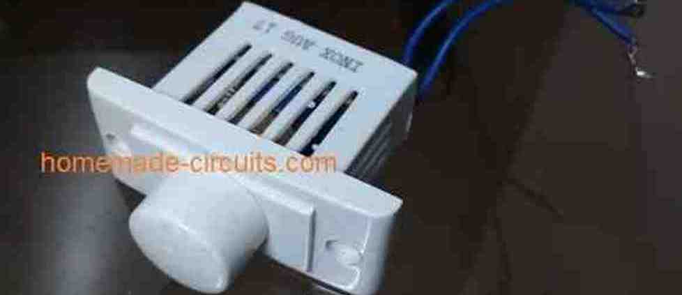
Simple 220V, 120V AC Light Dimmer Switch Circuit
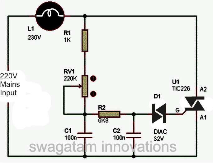
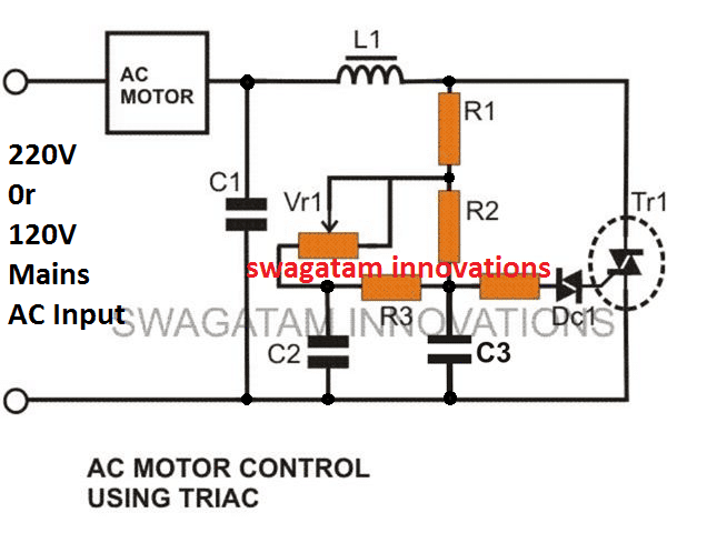
The circuit diagram shown above is an classic example of a AC light dimmer, where a triac has been utilized for controlling the intensity of light.
When AC mains is fed to the above circuit, as per the setting of the pot, C2 charges fully after a particular delay providing the necessary firing voltage to the diac.
The diac conducts and triggers the triac into conduction, however this also discharges the capacitor whose charge reduces below the diacs firing voltage.
Due to this the diac stops conducting and so does the triac.
This happens for each cycle of the mains AC sine wave signal, which cuts it into discrete sections, resulting in well tailored lower voltage output.
The setting of the pot sets the charge and the discharge timing of C2 which in turn decides for how long the triac remains in a conducting mode for the AC sine signals.
You might be interested to know why C1 is placed in the circuit, because the circuit would work even without it.
It's true, C1 is actually not required if the connected load is a resistive load like an incandescent lamp etc.
However if the load is an inductive type, the inclusion of C1 becomes very crucial.
Inductive loads have a bad habit of returning a part of the stored energy in the winding, back into the supply rails.
This situation can choke up C2 which then becomes unable to charge properly for initiating the next subsequent triggering.
C1 in this situation helps C2 to maintain is cycle by providing bursts of small voltages even after C2 has completely discharged, and thus maintains the correct switching rate of the triac.
Triac dimmer circuits have the property of generating a lot of RF disturbances in the air while operating and therefore an RC network becomes imperative with these dimmer switches for reducing the RF generations.
The above circuit is shown without the feature and therefore will generate a lot of RF which might disturb sophisticated electronic audio systems.
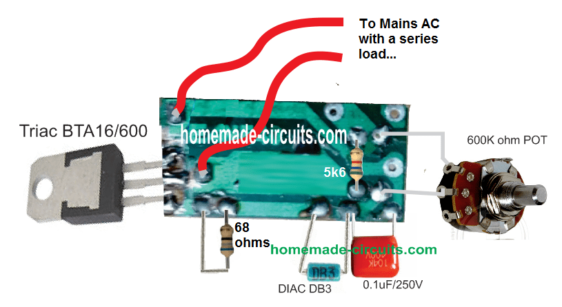
PCB Layout and Connection
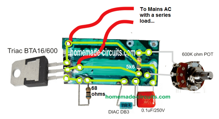
Track Layout Details
Improved Design
The AC light dimmer circuit illustrated below incorporate the necessary precautions for subsiding the above issue.
This enhanced design also makes it more favorable with high inductive loads such as motors, grinders etc.
This becomes possible due to the inclusion of C2, C3, R3 which allows the diac to be fired with consistent short burst of voltage instead of a abruptly switching pulses, which in turn allows the triac to be fired with smoother transitions, causing minimum transients and spikes.
Circuit Diagram of an Improved AC 220V Light Dimmer
Strip Board Connection Diagram

Parts List
- C1 = 0.1u/400V (optional)
- C2, C3 = 0.022/250V,
- R1 = 15K,
- R2 = 330K,
- R3 = 33K,
- R4 = 100 Ohms,
- VR1 = 220K, or 470K linear
- Diac = DB3,
- Triac = BT136
- L1 = 40uH (optional)
SCR AC Light Dimmer
An adjustable RC-type phase-delay AC light dimmer circuit is shown below which consists of R2. R3, and C1.
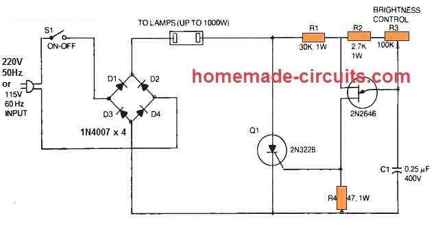
The capacitor C1 fixes the time period where a 2N2646 unijunction transistor (Q2) produces a triggering gate trigger pulse to turn on the 2N3228 SCR (Q1).
By some manipulation of the light-duty control, R3 pot the user is able to change the SCR output across a large range.
In the phase-control circuit, resistor R2 works like a security unit that inhibits rheostat R1 from getting fixed at 100 % anode voltage of the UJT.
This specific rule is applied here to regulate the illumination level of the incandescent lamps, whether as a single lamp or many in parallel as high as to 1000 watts.
In this design, a full-wave bridge rectifier is built using 4nos of 1N4007 silicon power diodes (D1 to D4) that supply rectified power-line voltage for the SCR and the lamp.
Due to the full-wave output from the bridge, it becomes possible for the SCR to take care of both half-cycles of the AC line voltage.
The phase-shift system is sensitive to frequency and has been designed for 60 Hz mains input only.
Therefore the circuit is not going to work with fluorescent lamps and should not be plugged into these.
The 2N3228 SCR 5-amps. 200-volts. but higher-powered SCRs could be replaced for high current applications, and the UJT 2N2646 section of the schematic could be kept unchanged.
Besides SCR circuit is supposed to be used like an AC light dimmer, this circuit can be employed likewise as a heater or oven controller.


Questions & Answers
hi sir, sir i want fan or bulb dimmer (AC)with touch module, ttp223,plz help me…
Hi Ghulam, let me investigate the design, if it possible for me I will surely update the schematic for you soon..
thank you sir, i will wait for your kind response
..
Ghulam, the following circuit is an IR fan remote control circuit…
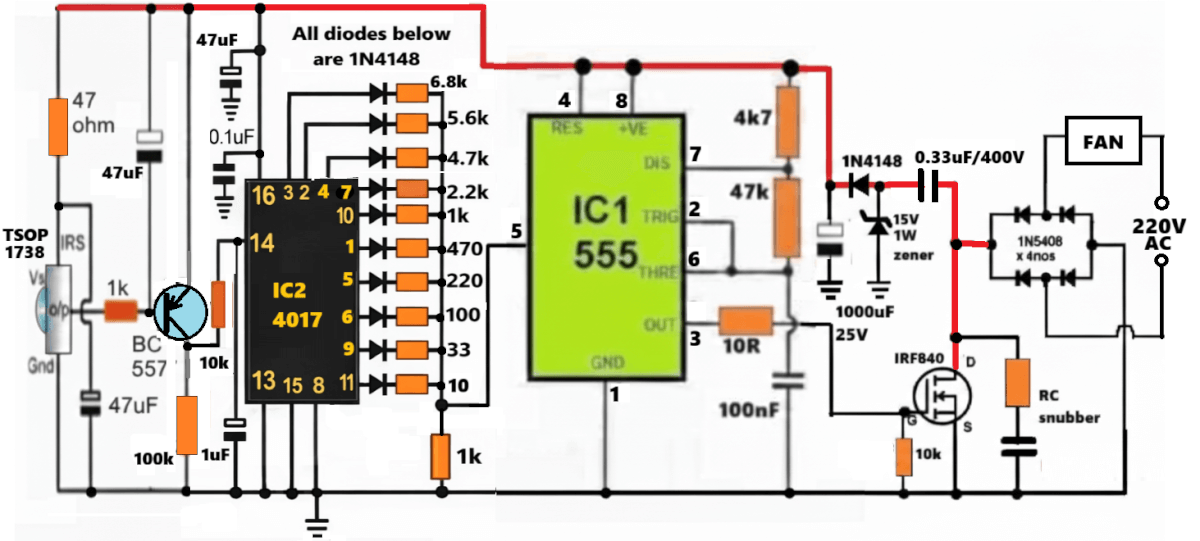
You can replace the TSOP1738 stage with a touch sensor with opto coupler, for touch based operation:
But LED bulbs will not work here…
Thank you much sir, i will try to make and update you, sir can we use irfzz44n insted of irf840? or can we use 21 volt adopter before 15volt zenor? and 7805 for touch module? because touch module need 3.7 to 5 volt.
Hi Ghulam, if you are using 220V AC for the load, then the MOSFET must be rated at minimum 400V, so please check your MOSFET specifications accordingly…yes a separate power supply adapter will be good for powering the DC circuit, for better performance and isolation from mains AC…
sir plz guide me at which part i have to use power supply? before 15 volt 1 watt zenor or no need zenor diode in that place i have to use 12 volt power supply?an the other end for ttp223 touch module lm7805 where need to be connected? OR can i use 5 volt adopter? pls guide me with digram plz
The resistor associated with the 4N35 opto LED can be a 1k resistor…
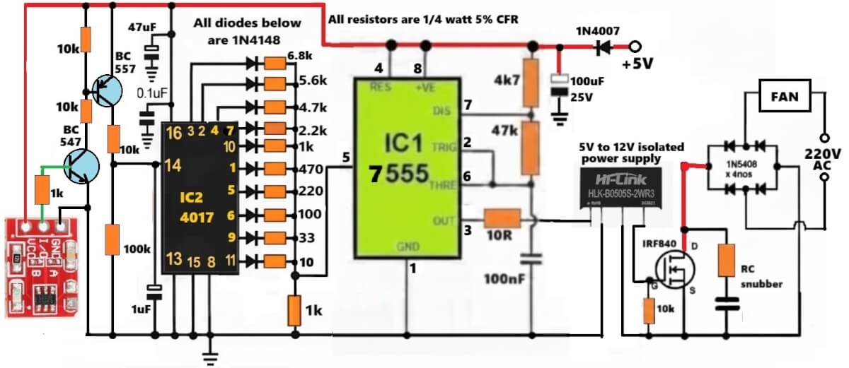
Ghulam, you can try the following diagram, external power supply will be required required:
I have a device with a 6VAC bulb. I have a power supply of 6VAC, 1.67 Amps. I need a dimmer to go inline to adjust the brightness of the bulb. Is there any available that you know of or do I need to contruct my own and if so do you have any info on the schematic to build one?
Please try the following circuit design, I think it should work:
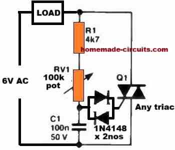
Please let me know how it goes…
By the way, you can simply convert 6V AC to 6V DC and use a BJT circuit to control the bulb intensity, because the bulb can illuminate through both AC or DC supplies?
When I build AC light dimmer, the VR also gets heated. Is it normal and the VR will not be damaged in the long run?
No, that’s not normal, the VR has series resistors connected with it so it should not heat up at all, please check your circuit connections again.
hi swagatam,
I notice a issue with the conventional fan dimmer those are avilable in market , that has a triac in it , that when I connect a voltmeter (robu model : AD16-22FVA) at the output of the dimmer and take it to 0 position , the voltmeter shows 303v instead of 230v mains, also a resistor designed to work internally with the voltmeter makes a humming noise and after running the circuit for 2 minutes burning smell comes from the voltmeter, the voltmeter is absolutely fine but I dont understand this abnormal behaviour, here I have made a video album to show the same issue . link – https://photos.app.goo.gl/Kj1cQXsRSsB8Y9qEA the first video is of the dimmer in 0 position . the last video is the situation if i used the item with dimmer 0 position for a longer time, I have used a same item but another one just to confirm that my video item has no issue. its exactly same there also
Hi Preetam,
Did you try measuring the voltage with a incandescent bulb connected? Please try this, measure the voltage across the bulb.
Alternatively you can try using a moving coil type meter instead of a digital meter, or you can try a true RMS type voltmeter.
The issue could be because the dimmer chops the AC voltage to create abnormal waveform which may not be compatible with standard DMMs.
yes sir if I connect the bulb the voltage shows ok , but as soon as I removed load the voltage is abnormal + a constant humming sound always comes , might be this is due to the uneven waveform created after chopping voltage by dimmer .
In that case the problem may not be with the meter, it could be something to do with the loading of the triac. When the triac is loaded with the bulb, it could be stabilizing the triac conduction and the waveform.
The actual problem can be perhaps diagnosed by checking the waveform pattern through an oscilloscope connected parallel to the voltmeter.
Hi Mr. Swagatam;
Re. to above simple AC light dimmer circuit;
Is it possible to use a bridge rectifier diode as the load and having the dc 84V as the output voltage?
Hi Suat,
Then the average voltage will be 84V but the peak voltage can be 310V, which can be dangerous….
Is it possible to mention about the danger details. For instant shocking hazard
or overheat danger at high voltage side or disharmony between the ac and dc side
or faulty for the device to be used as the load or similiar?
Regards
The danger will be to the load and also to human being.
If the load’s working voltage is 84V, it cannot tolerate a peak of 150V or 200V etc and will quickly get damaged.
The high peak voltage can be dangerous to human beings also.
Hi Mr. Swagatam;
While the load is 220V 100W bulb and circuit is set to the highest level, my multimeter shows the voltage value between 197V and 212V. But oscilloscope shows 228V as the RMS voltage. So in this situation, is it possible to say that multimeter shows the correct value since the load is attached?
P.s: Simple AC light dimmer circuit is subject
Hi Suat,
Since the pot is at the maximum position, the voltage across the load should be almost equal to the input AC level, which should be around 230V, so, 228V appears to be the correct result, by the oscilloscope.
Hi Mr. Swagatam;
Multimeter gives the value between 184V and 220V at the output of the simple AC light dimmer circuit when the pot is rotated from lowest to highest value.
But It is not possible to see any different / various value on the the oscilloscope display even the pot is rotated to low or high position. I always see te fix / same value like : min-328V max 324V avg -4.00 v rms 231V vpp 652V vp 328V.
Is that normal or there is the point I miss?
Hi Suat,
Please connect a 220V incandescent bulb load in series, and then check the response. The waveform will clearly indicate the working of the dimmer.
Make sure to connect the scope across the bulb.
I have a few questions about the Improved Design, the 2nd from top. In the image it has a 47uh choke and in the parts list it says it is a 40uh choke. Which is it? Also, should it be an air wound or ferrite core?
I also see that the Triac in the image is a BT139 but, in the parts list it says a BT136. Which is it suppose to be?
Last is the .022uf 250v capacitors. Is there a specific type that is recommended like (Metallized Paper type) or (Poly Film type)?
The inductor value is not critical, the higher the better. It can be an air core or ferrite core, or iron core, its the inductance value that matters.
The triac can be any triac, depending on the load current and the supply AC voltage spec.
Capacitors can be metallized polyester or simply PPC type.
Thanks for the quick reply. I figured I would try this out and wanted to make sure I did`nt get the wrong type of capacitors. I will wind my own choke/inductor. My plan is for a variable temp. soldering iron using a cheap 50 or 60 watt 120vac iron. Thank you!!
Ok, thanks for your feedback! All the best to you.
Hello sir Swagatam, is it possible to ask for a copy of how you solved for the values of the components of the circuit? I am a student and I am tasked to build a similar circuit as yours, with given specs for the AC input and lamp, for a project, but I don’t know how to start. I would like to self-learn how to do this circuit from scratch, by solving the values of the resistors and capacitors. Thank you and sorry if my request is too heavy.
Hello Kai, I understand that you want to know the calculations details of the above circuit, however calculating the RC parameters can be quite difficult because there’s no easy formula to calculate them with a 220V AC parameters. I got these circuits from other online sources.
However, I can approximately tell you the functions of each of the parts. In the first circuit, R1 provides a fixed dimming value for the lamp in case the 220k pot is rotated to its minimum range. This ensures that the bulb does not shut off completely at this minimum range of the pot, otherwise due to hysteresis the lamp may not illuminate until the pot was turned at around midway. You can select R1 so that even at the minimum pot rotation the lamp gets the minimum glow on it and does not shut off completely.
The capacitor C1 also interacts in the same way, its value must be selected so that when the pot is rotated at its minimum range the lamp reaches its minimum glow and does not shut off completely.
R2/C2 decide how soon the diac must be fired again determining the minimum or maximum illumination of the lamp at a certain pot rotation, which allows the diac to be fired with consistent short burst of voltage instead of a abruptly switching pulses, which in turn allows the triac to be fired with smoother transitions, causing minimum transients and spikes.
Thank you for the response sir Swagatam! I would also like to ask how you chose the diac and triac for the light dimmer circuit. Can any diac and triac be used? And is it correct that I should base the values of the resistors and capacitors with the datasheet info of diac and triac? thank you again.
Hi Kai, the diac can be any diac, but the triac’s amp rating must be as per the load specifications.
Although the resistors provide the required protections to the diac and the triac, their values are mainly dimensioned for controlling the firing angle and timing of the diac and the triac.
Hi Mr. Swagatam;
I have input 120V air fryer but our main voltage value is 220V AC.
Is it possible to use that home appliance by using above dimmer circuit.
Regards
Hi Suat,
No, that is not recommended, because although the dimmer may provide a 120V RMS, the peak voltage can still be around 220V, which can be detrimental to the appliance.
so could you please advice a converter circuit 220AC to 120AC if possible.
Suat, Actually, your air fryer is a resistive load, so yes you can use a triac based dimmer circuit to convert the 220V to 110V, it will do the job.
thanks for the support, is it possible to use buck converter type circuit instead or which one is better dimmer or buck converter.
Buck converter is always better but for resistive load you can use a dimmer circuit. I currently do not have a 220V to 110V converter circuit with me, so unable to provide it to you.
Hello, and thank you for sharing your circuit designs.
I’m trying to build the “improved” AC Light Dimmer (2nd design above), I ordered the parts and now I’m in the phase of creating a layout for a piece of stripboard, using “DIY Layout Creator” software.
You can see my tentative layout here: https://ibb.co/k841cQ8
The green wires are my vertical connections, I think they’re OK, but I’m not sure about the small pink wire connecting 2 pins of the potentiometer, maybe it’s useless?
There are 3 trace cuts, the one next to R4 is useless for the moment but I plan to add a switch to the circuit so I added it to not forget…
I could avoid making 2 trace cuts and 1 wire soldering by connecting directly R3 between C2 and C3 horizontally, I suppose. I might do that if I find the horizontal space in the final design.
The BT139 TRIAC has its Gate leg on 3rd strip starting from the bottom, connected to the DIAC then through R4.
So I guess everything’s OK but I want confirmations before soldering it since it’s my first stripboard project…
Can you also confirm that I could connect a switch where I put the green arrow?
Let me know if you see any error, especially regarding the values of capacitors, resistors or anything. Thanks!
Hi again,
Ok, I could open the image in the TOR browser.
Let me check it.
I will let you know if there are any issues in it….
I checked the design, and I could not find any issues in the design, everything seems alright.
Yes, you can put the switch across the indicated positions, make sure to cut the track in that position.
Thank you for your answers, it’s appreciated!
Some modifications:
Do I need to keep the pink jumper wire or can I remove it?
I’ve inserted a SPDT switch as you can see on the image. I don’t think trace cut is needed with this configuration, am I wrong?
Thanks again.
Trace cut is required between the yellow wires otherwise the switch will not work.
Pink wire can be removed, it is not required.
Of course, I had not thought that without trace cut the switch would be rendered useless 🙂 Lack of sleep I guess…
You can use the final compact layout for veroboard/stripboard on your site, if you want:
Thank you for your time, bless!
Thank you for the feedback. Sure, I will use the new diagram in the above post, I hope the readers will like it.
Hello, I made some corrections because trace cuts were needed between the legs of horizontally mounted components (L1 & R3), otherwise they were simply shorted.
I’ve also attached the potentiometer and switch on a box chassis to make it more usable, so they’re connected to the board only with wires.
Please find the updated layout here: https://imgur.com/a/DODvzjN
Have a nice day and thank you for sharing the layout.
OK, Great! Thanks for the updated diagram, it looks much better now.
Hi there, Thanks for posting this question! I will try to solve your query, however, the link that you sent simply refuses to open in my chrome and edge browsers. The ibb.co website always throws this problem.
Could you please use some other image upload website and send the link here again? I will try to figure it out.