LI-FI is buzzing around the Internet since past few years; recently LI-FI is gained more popularity around the internet and developers. LI-FI stands for Light Fidelity which was coined by Harald Hass.
Circuit Objective
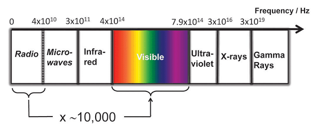
The objective of LI-FI is transfer data through visible light. Since the bandwidth of visible light is 10,000 times more than Radio waves, more data can be transferred through light at short period of time.
Visible light communication (VLC) eliminates the risk of some disease caused by the Radio waves due to long period exposure.
This protocol can be adapted where Radio waves are restricted, such as airplanes, hospitals, and in some research facilities. Researchers reached bit rate of 224 GB/s which is 100s of times faster than our average WI-FI connection at home or office.
This article explains about the basic idea how to make a very simple LI-FI circuit in which we will be able to transfer any audio source through light and receive it from the receiver which is placed few feet from the Transmitter.
Here explained about analogue communication through light, where as original LI-FI system uses digital communication, which is more complex and difficult to make one at hobby lab. But the concept is exactly the same.
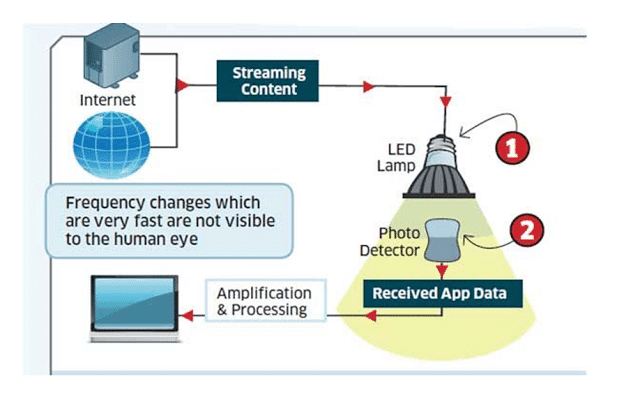
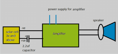
Here is a simple block diagram explaining LI-FI:
The Design:
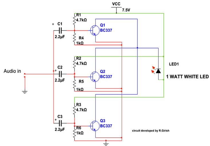
The circuit consists of two parts, which are receiver and transmitter. The transmitter consists of 3 transistors and few passive components paired with 1 watt LED. The transistors are configured as common emitter amplifiers which alters the LED brightness with respect to audio signal.
But changes in brightness due to audio signal will not visible to human eye. We only see static illumination of white LED. The receiver consists of a photo detector (here I used solar cell) which is paired with an amplifier. The sound output is given by the speaker.
The transmitter is transistorized amplifier which consists of 3 amplifiers connected in parallel to drive the 1 watt white LED.
Each transistor base consists of voltage divider which gives necessary bias for the individual transistor. The input stage has capacitors at each transistor’s base for blocking DC signals which could degrade the quality of output.
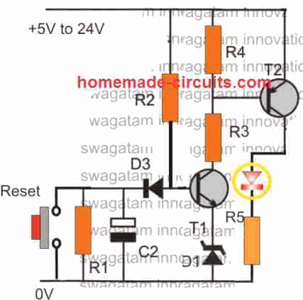
LI-Fi Circuit Diagram
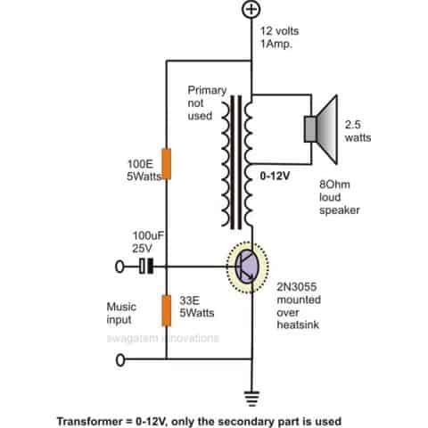
Update: The above design can be also tried using a single transistor as shown below:
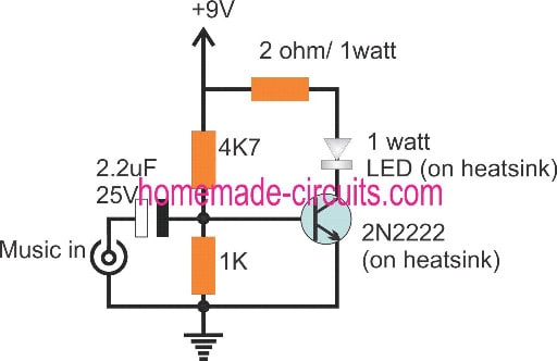
You can use a current limiting resistor series with LED if you want operate the circuit at higher voltage (say 12V).You can also use standard 0.5mm white LED with current limiting resistor. For an audio source you can use mp3 player, mobile phone or a microphone with pre-amplifier etc.
The receiver consists of a 6 volt solar cell (3 volts above works fine) in series with 2.2uf capacitor which is paired with an amplifier. The amplifier need not to be the same illustrated here, but you can use any amplifier lying around your house. But make sure it as good sensitivity.
Amplifier Schematic
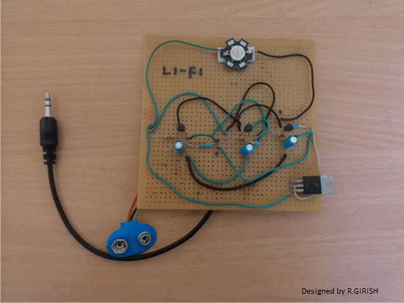
Here is author’s prototype
Li-Fi Video Clip:
You can use any amplifier with good sensitivity for receiver part. To test this circuit, go to a room where ambient light is dim and make sure no nearby electrical light source.
Place the 1 Watt LED parallel to solar cell. Turn ON the power supply for both transmitter and receiver, give audio input to transmitter, adjust the volume to transmitter. You can here clear audio sound on the receiving speaker.
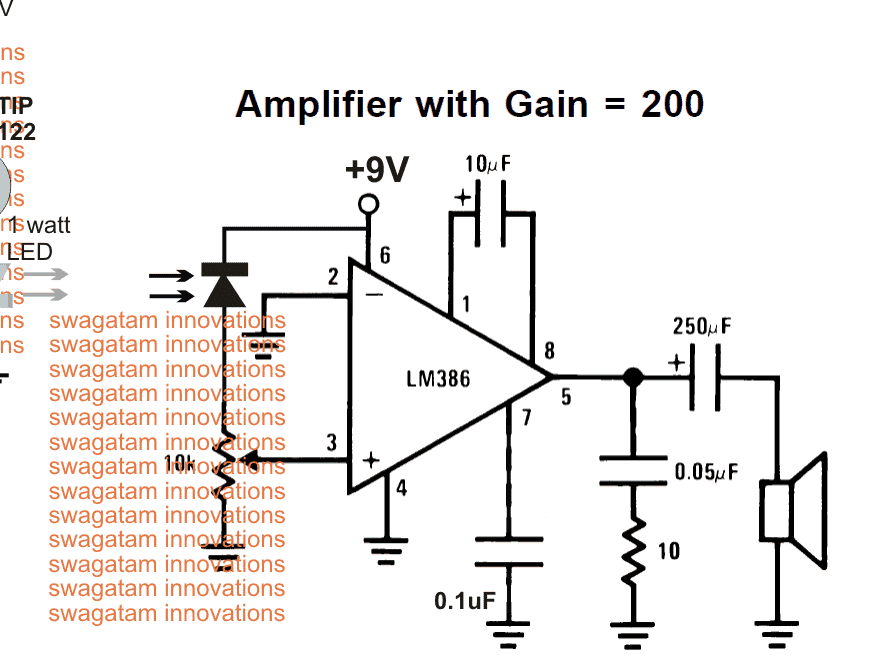
The above explained Li-Fi circuit can also be tried using a photodiode as shown below, where the amplifier section is replaced with a LM386 amplifier circuit:
UPDATE:
Some Important Notes and Considerations Regarding the above Li-Fi Circuit
In this Li-Fi the LED does flicker, but it is in-significant for our eyes to detect.
If your eyes can detect those flickers, something wrong with the build.
The change in the brightness of LED due to the audio input is very small, but there is change in the brightness, where our eyes can’t detect.
If there is no audio input, the LED stays solid ON, the solar cell produce some voltage. The input capacitor at receiver blocks those DC signal giving almost zero voltage to amplifier.
When we apply audio signal at transmitter there will be change in the LED’s brightness (Very small). The solar cell replicates the small varying voltage, the capacitor will allow the small variation in voltage amplitude to amplifier and rejecting strong constant DC voltage.
The amplifier must have good sensitivity since the input is feeble. Probably that’s why many readers are commenting on loudness of the audio.
I have used old-school home theater’s amplifier which had very good sensitivity and the resulting output was LOUD and CLEAR.


Questions & Answers
Hii,
What is the use of 2N2222 transistor in the circuit diagram. Can you explain whole circuit diagram please I will be very thankful for that.
Please respond as soon as possible
Thank you in advance
2N2222 is configured to work like a simple common emitter amplifier circuit. It amplified and music across its collector so that the LED is able to respond according to the music amplitudes.
This is mind blowing, thanks for sharing.
Hello,
Have you got the procedure for finding why the particular values of resistor and capacitors
I will really appreciate you if you can provide the procedure or atleast the reference for it.
If you have the procedure do mail it to
14bm047sakshay@gmail.com
All the values are experimented to get optimal amplification…..if you alter the resistor values, the output amplification will be effected, similarly if you alter the capacitor again the amplification will get effected….the resistive divider limits the input amplitude or the peak voltage, the capacitor limits the current.
Does it need to turn on mobile data to play music in youtube?
Here the signals that are transmitted are analog i think so, then the output in led will be analog too so how this is lifi ?
The purpose of Li-Fi is to communicate signals or music via light, it does not need to be digital.
Thanks for sharing this is really helpful for me and also for my upcoming project. hope you add some more in future also. thanks for sharing
You are welcome kimmy.
Sir
Have u got projects on internet generation and transmission using LiFi
Ololo, sorry, I do not have any other article related to internet lifi other than this one.
Hi there!!!
for transmitter part we are using almost same components (as shown in figure with 3 transistors)…
for receiver part we are using solar panel (5V 1.25W) followed by amplifier circuit with LM386, however we have not used 2.2uF capacitor in series with solar panel…
our receiver part is probably not working as we are not getting any sound in speakers…transmitter part is working as we have tested it with 5 Hz test tone as audio input, we were able to see LED flickering
kindly help us…
Hi, please replace the photodiode with an LDR in the LN386 circuit, and make sure to connect a 2.2uF or any capacitor in the range, in series with the pin3 of the LM386
sir, I am working on the research project on Li-Fi. I would like to connect Li-Fi receiver to the FPGA . can you help me with the circuit diagram
I have a simple question … if we switch the transmitter and receiver between two devices does it works in lifi technology?
also, I found some devices on the internet they work with the help of USB. I would like to replace the USB cable.
Sai, Sorry I do not know much about FPGA technology, but any high frequency will be accepted and processed by this Li-Fi circuit.
As long as the input is a high frequency signal, the LiFi will work across the selected devices.
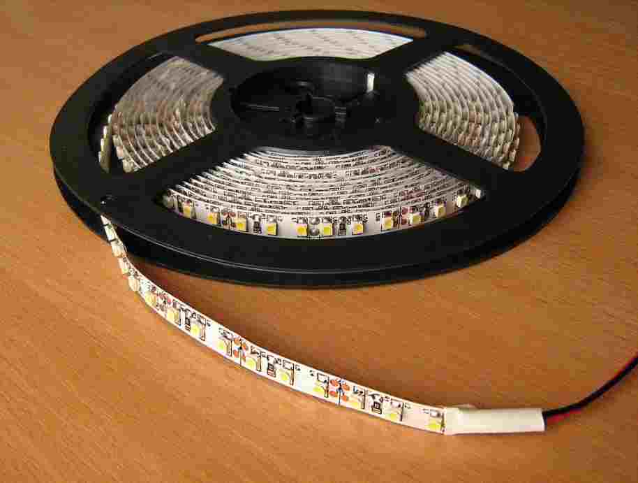
Bro i used a led strip instead of a led bulb and a 3v solar panel and now the lifi is not working where maybe the problem be where should i make a change in the led or in the solar panel?
Rahul, first build and verify the basic design which is explained above. If you succeed with that then we can proceed and modify it with an LED strip, and check the response!
I made the circuit as given above but used a 3v solar panel and it is not working should i use a 6v or 9v solar panel? Plz reply fast i have to submit it today evening.
Did you check your amplifier normally using a music input? First check whether your amplifier is actually working or not? Any solar panel will work for this application…just make sure no other light except the Li-Fi light falls on the light sensor (solar panel)
sir
i do not want the anologue experiment help with the minimal materials i need for this
moreso from my last post do i have the required material if not help me with what i need for the digital experiment perhaps i didnt find the article
Thanks on the receipt of your wonderful detail swaga
Kindly help me with detail for the digital LiFi transmitter and receiver
Ololo, the explanation for a digital LIfi circuit is given in the above article, so please go through it for detailed understanding.
may be you can try the following concept
https://www.homemade-circuits.com/lifi-internet-transmitter-circuit/
sir
i just got a 3 watts solar panel to be used as a photodetector, three 6 watts LED wifi panel bulbs,and fresnel lens for an amplifier
please is this enough for a room LiFi
internet
i realy want to know if the fresnel lens is a must since its in a room because its hard to get fresnel lenses in nigeria
help
ololo, the minimum things are already specified in the article, you will just need those minimum things for the experiment, fresnel lens may not be necessary, please do exactly as explained in the article.
hi swag …can i send data more then 1M mebe text file or a picture for 2meters ..and can i buy it and export the circuit
for iraq
Hi hassan, sorry this design supports only analogue signals, digital signal might not work correctly.
sir,
i’m a final year undergraduate student working on applications of li-fi: indoor positioning using lifi. can you please tell me how to use this circuit for positioning.
and what is the distance between tx and rx to be placed
Sunil, as long as the light sensor is able to receive the light from the LED it will work, the distance will not matter, but you will make sure that no other ambient light reaches the sensor…
Sir, can u please make some video showing connections and working of the project.
SIR SOLAR IS BETTER OR PHOTO DIODE IS FOR TRANSMITTER CIRCUIT
Gajendra, solar cell will be easier to configure, photo diode will require some technical consideration…so solar cell is the easier option.
both are equally good as far as results are concerned..
Hii swag
I make lifi Circuit same as your Circuit diagram from above. But from wheres i will provide power supply i dont know,
Means R1 connect to +ve and R6 connect to -ve of battery ??
Om, the Vcc line is the positive, and all the wires linked with this line are positive.
similarly all the wire links joined with the ground symbol are negatives.
use 5V as the supply