The explained 5 circuits below are universal simple audio mixer circuits, that may be customized and upgraded to 5 channel or even 10 channel mixers, as desired by the user. Contributed by: Anil Rao.
Stereo Audio Mixer
The operation stereo audio mixer circuit shown below is straightforward: If a mic is "being used," its output is applied to the MIC input port of the circuit.
The signal is subsequently applied to R1 or R2 (which are utilized as faders). The signal is after that divided into a couple of diverse routes through resistors R3 and R4 using which it is possible to alter the location of the MIC inputs within the stereo range.
The stereo line inputs are simply built for this. Connecting the MIC inputs with the output of any different source, like a mobile phone or PC USB or CD player, etc., all of the signals are supplied to the inverting input of an op amp. The output extends to the master-fade potentiometers, that handle the output power.
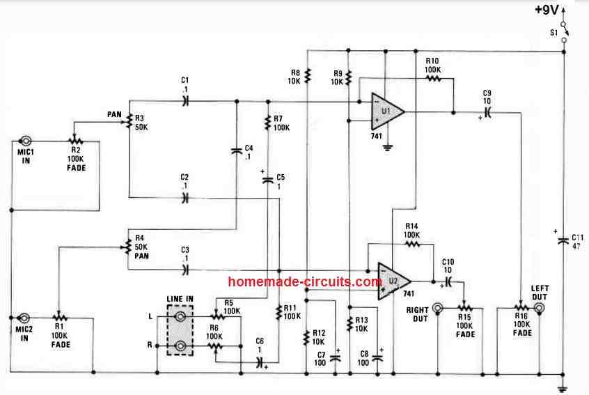
This stereo mixer circuit is additionally simple to customize. For instance, We replaced low-noise amplifiers for the 741's, and employed 1% metal - film resistors.
We furthermore made use of slide potentiometers for the faders and line -level controls. We modified the quantity of in puts also. Rather than just a couple of MIC inputs and a single line input, We expected to get a total of 8 MIC inputs and 4 LINE inputs.
4 Channel Audio Mixer using a Single Op Amp
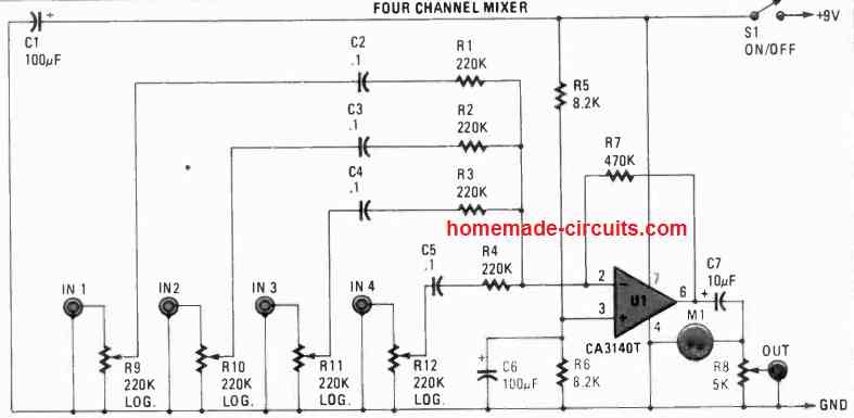
The next image shows a 4 channel mixer, in which 4 different audio signals can be fed to the indicated relevant inputs IN1----IN4 ports, the opamp will mix them all to produce a common mixed output at the port indicated as OUT.
4 Channel Mixer with Tone Control
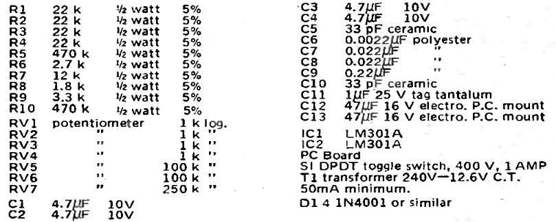
Pats List for 4 Channel Audio Mixer
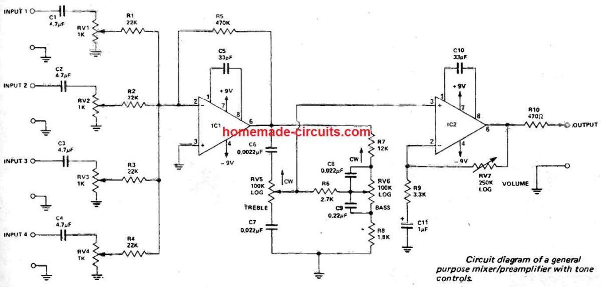
The signal supplied by means of a sensor involving audio frequencies, for example a microphone, a guitar-string sensor, etc all require a signal boosting before the output can be used to drive a main amplifier.
The 4 channel preamplifier displayed above can work with signals as low as 2 mV levels, comes with an input impedance of 1 k, offers a gain of around 1600, and provides an output swing as high as 3.2 V for 2 mV input.
It exhibits relatively small distortion and is built to accept four external inputs, all featuring their own level control.
An exclusive tone control system is integrated that allows bass and treble signal frequencies to be adjusted through a range of ±10 dB (at 100 Hz and 10 kHz respectively).
Even though largely designed for mixing audio signals in leisure purposes, the circuit could also be applied as a single-input, adjustable -gain unit in just about any application where gain and frequency modification are essential.
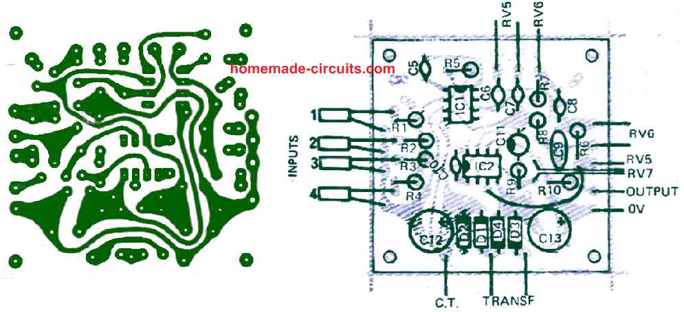
PCB Designs
Single Transistor Audio Mixer
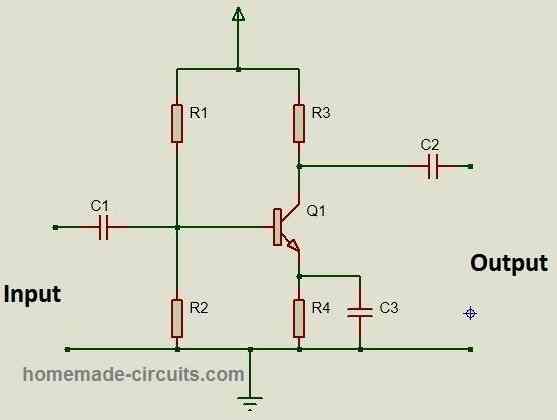
An audio signal mixer can be actually as simple as the one indicated in the below diagram. This circuit uses just a single transistor and can be used for mixing 3 input signals or even more than this number.
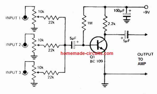
Although only 3 inputs are shown that doesn't restrict it from incerasing the inputs, which may incerased to any higher desired inputs.
Each of the mixer inputs can be seen having their individual level control pots for adjusting the amount of signal that can enter through the inputs, independently.
This single transistor mixer circuit is designed for amplifying the any input signal with a 50 mV, to an output signal of around 500 mV, which is more than enough for most power amplifiers configured at the output.
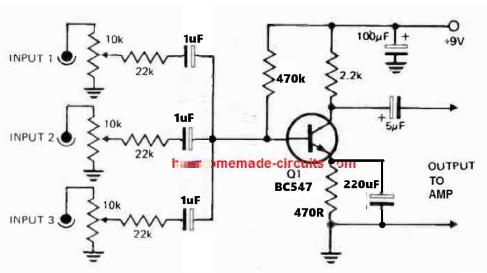
The above design can be further improved, as shown in the following diagram:
MIC Mixer Circuit
This uncomplicated mic mixer circuit enables you to blend a high-level source with a low-level microphone input for amplification purposes.
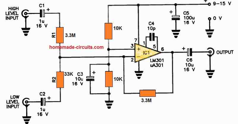
Within this setup, the high-level input maintains a one-to-one unity gain from input to output, while the low-level input experiences a substantial gain boost of 100.
To eliminate the need for split supply rails, the non-inverting input of IC1 is artfully biased to a voltage level precisely halfway between the supply rail's positive and negative potentials, and this bias point is effectively filtered by C3.
Capacitors C1, C2, and C6 perform AC coupling, permitting the desired signal components to pass through. C4 serves the vital role of compensating IC1, ensuring signal fidelity, while C5 efficiently bypasses any supply rail noise.
This circuit can be efficiently powered by a single 9 V transistor radio battery, and it's advisable to include an on/off switch for convenient operation.
With this straightforward design, you can easily blend and amplify high-level and low-level signals with precision and efficiency.
5 Stage DJ Mixer
Five stages are employed within the layout; DJ mixer stage; Mono headphone amplifier stage; Balanced-microphone preamplifier stage; Stereo VU circuit stage, and General purpose preamplifier stage.
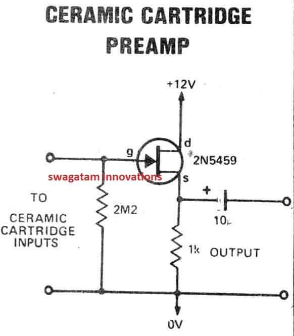
A basic ceramic cartridge preamp is displayed that looks so straightforward that it could be constructed on the input sockets itself!
When using the stages outlined above practically any audio options could be mixed or blended by the user to get a stereo transmission specifically suited for driving power amplifiers straight away.
The mixed signals may also obviously be applied to feed headphones etc. The inputs from CD players, microphones, Ipods, cellphones etc should be appropriately matched up to the inputs of the mixer board. To get this done the proper preamplifiers needs to be determined and built.
Even so, the audio mixing range could be practically endless. Before you start building consider which preamplifiers you might need, consider which kind of sockets you would like to work with, and the number of channels you would like (although demonstrated as 4 channel, the mixer could be extended with the addition of further control pots and mixer resistors).
BALANCED MICROPHONE PREAMPLIFIER
The best thing about this balanced microphone circuit is that it gets rid of a pricey line transformer.
Even though intended for 600 ohm input and 40dB gain, various other impedances and gains could be dealt with by using R1 = R4 input impedance divided by two R5 = R11 voltage gain multiplied by the value of R3. The very first equation functions for impedances of approximately about 5k.
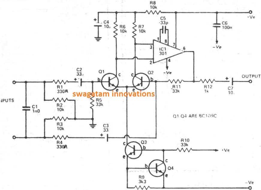
Over this figure R2 + R3 need to be incorporated in the computation. Even though we all posses just one input, the output from this circuit makes it possible to griddle the output through stereo by utilizing a couple of 10k resistors or a 20k linear pot using the wiper attached to the output enables you to pan the output via left to right.
In case a balanced MIC is applied R2 values will be as follows microphone R2 = 4k7 (limiting R2 47k) if employed with balanced preamp as input to restrict R2 = 15k
MIXER AND POWER SUPPLY
Due to the excellent feature of excessive ripple rejection ablity by the incorporated integrated circuits across different segments, the power supply specifications actually tend to be quite straightforward. A simple bridge rectifier, large smoothing capacitors having a RF bypass capacitor and you own a good power reference.

The inputs through cellphones, SD cards, USB microphones etc has to be amplified or possibly equalized with a pre-amplifier prior to any kind of controls positioned to process them.
The output of each of such preamps is variable using a volume control or fader, previous to being added to lC1. The total gain of the mixer stage could be modified through RV1.
If various preamps possess largely varying output voltages the value of Rl-R4 could be improved in order to match them.
The output of lCl is connected subsequently to the tone control stage. lC2 typically features a unity gain when the pots are moved at the center of the dial.
However, this gain is actually variable, with regard to frequency, when the tone controls are not around the center the output of the tone control stage specifically toggles the main power amplifiers.
This output is additionally rectified by Dl to run the meter circuitry. The mixer provides stereo outputs which is accomplished by replicating the circuitry for the second channel.
The exemption may be the tone controls that are dual gang potentiometers.
Remember that the volume controls are separate units.
The power supply is actually a full wave rectified supply using a center tap offering about 1 VDC
How it Works
The resistors linking Left and Right channel outputs are positioned to get a composite mono signal, without severely deteriorating the main mixer stereo separation.
The signal is actually picked by SW2-SW5 and raised on to a buffer having adjustable gain (IC3). The output can now be given to a LM380 power amplifier that runs the monitor headsets. Just like the mixer the input resistors may be made higher, to minimize high signals towards the other channels.
The mixer is actually a standard summing amplifier using adjustable feedback (ie gain), accompanied by a Baxandall tone-control system.
In case input ranges aren't of the identical value, the 27k input resistors could be modified to decrease the highest signal by increasing resistor value. Avoid lowering under 27k because this may decrease overall level of sensitivity of the mixer.
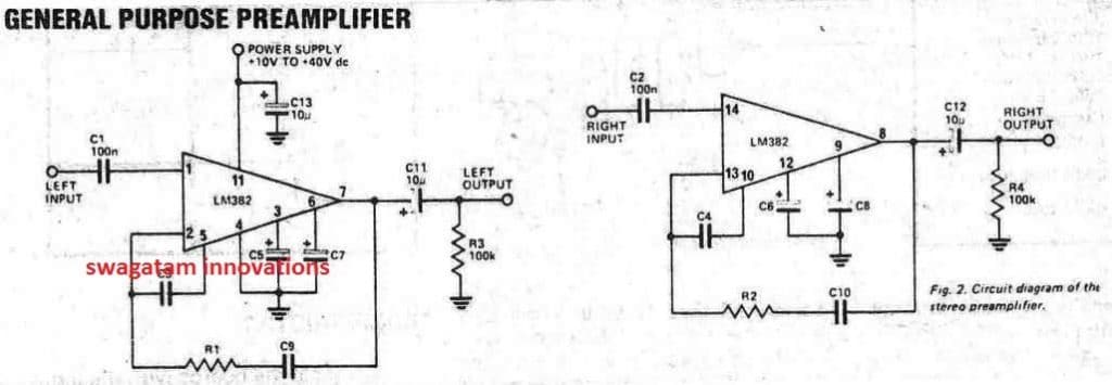
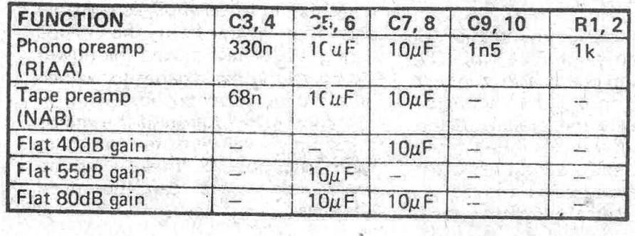
UNIVERSAL PREAMPLIFIER
How it Works
Very little can probably be said about how exactly the LM382 operates since many of the circuitry is comprised inside the IC. The majority of the frequency determining elements are on the chip just the capacitors tend to be attached outside the body.
The LM382 has got the handy feature of obstructing ripple on the supply path around 10 dB. Hence significantly lowering the high quality dependence on the power supply.
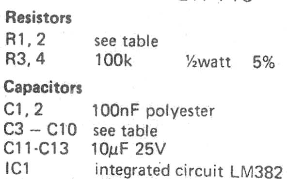
Parts List for Universal Preamplifier
4 CHANNEL STEREO HEADPHONE AMPLIFIER
The output through each preamplifier could be applied into this headphone amplifier circuit.
To be able to cue signals prior to mixing them into the output it is strongly recommended that if headsets are used, include a 100 ohm 1 watt resistor which may be installed in series with the output.
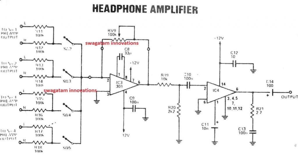
This is primarily to safeguard your ears and decrease the power dissipation of the LM 380 or else a little heatsink could be needed. The volume control could be attached to the trunk of the mixer since it is not necessarily tweaked frequently.
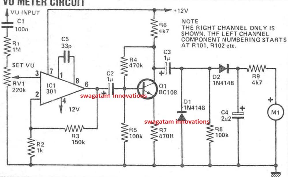
VU CIRCUIT
The VU meter circuit utilized in the mixer board is quite fundamental, yet well suited for several similar audio level indicator purposes, distortion presented into the output signal can be as much as 2% THD, therefore we highly recommend the VU board.
Possibly you may leave out RV4 and D1 from the mixer board and hook up point X to the input of the VU panel. Calibration set up is performed through the preset on the VU board, give a signal input via the mixer until eventually the output is merely distorting the amplifier, and fine-tune the preset to signify +3VU.
CONSTRUCTION
Construct the boards using the overlay sketches, to save your time we have placed all the PCB layouts collectively, here.
The picture exhibits the general layout we made use of, however this is universally adaptable, ours had been constructed into a wooden box along with metal front side and bottom nevertheless a metallic container could be a lot more ideal within an electrically raucous atmosphere.
Inter-board cable connections could be figured out from the specific circuits and overlays.
All contacts needs to be as small as you possibly can and retained far from the mains wiring.
We actually relocated the power button directly to the backside of the panel to minimize hum pickup and grounded to the metal box, having an light weight aluminum shield round the mains transformer to guarantee minimal hum pickup).
If this is carried out unscreened cable connection may be used without issues.
How it Works
This VU circuit comes with an input impedance approximately 1M and consequently will never load the mixer output by virtually any visible level.
The IC features a gain of 43dB, the signal can now be amplified through Ql to attain sufficient level and push the VU meter needle.
With no signal circumstances the voltage in the penetration of D1, D2 drops to 0V due to R8.
Each time a negative proceeding signal shows up at collector of Q1, C3 tends to discharge within the negative peaks. Difference between negative and positive highs is shifted via D2 to C4 and therefore is indicated on the VU meter reading.

Questions & Answers
Hi Swagatam,
I’m the designer of the TEC-1G which currently has only a bit-banged output from a 74HCT273 going to a speaker. I want to make a Sound Card for it that takes the output from the onboard bit-banged data line, and has two other outputs on the card, one being the SP0256-AL2 speech processor, and the other a SN76489AN noise generator. I need to mix all three inputs and amplify them to an onboard 8ohm mini speaker. Could you recommend which of the above circuits would be best suited to the task, considering all three inputs have different and varying voltages? I’m quite proficient with PCB design, but if there are any tips you can pass on, I’d gladly take your suggestions on. (Eg,. Should I go 4 layer and try to shield the inputs as best I can?)
Hi Mark, for your application the following active transistorized mixer stage would probably be the best choice among the circuits discussed.
https://www.homemade-circuits.com/wp-content/uploads/2017/04/BJT-audio-mixer-circuit-hi-fi.jpg
You can feed the mixed output into an LM386 or PAM8403 amplifier stage for driving the 8Ω speaker.
A good 2-layer PCB with solid ground plane should be sufficient. I would mainly recommend keeping the digital bit-banged traces away from the analog audio section and perhaps adding a simple RC low-pass filter at the bit-banged input to reduce switching noise.
Thanks for the speedy reply! I have two problems using those circuits:
1) I don’t have 9v power. Only 5v. 😢
2) Maybe I’ m not following, but that circuit you linked has two outputs? Or is the lower one connected to ground?
I know it’s alway a bastard to look over other people’s circuits, but I’d be happy to pay for your time to take a look over mine and give any feedback. I’ve also included some screenshots of the 4 layer PCB to show how I’ve laid it out. The physical aspects of it I can’t change (size, location of connectors and volume control) but if you have suggestions for moving around other parts, I would gladly welcome. As you can see I’ve gone to some lengths to keep the noisy digital parts separated from the audio section.
(I might re-arrange the Schematic to more cleanly delineate between the digital and audio sections. I know it looks like spaghetti compared to your clean circuit diagrams. Sorry!)
Here is the link to my GitHub page for the Sound Card:
https://github.com/MarkJelic/TEC-1G/blob/main/TEC-Deck/SoundTalker/Readme.md
No problems, your comment was actually sent to the spam folder because of the link, now I restored it back.
Since I am not a professional PCB designer, assessing your PCB can be difficult for me, although overall it looks good to me from outside.
Surely, you can rearrange the schematic as you want, just make sure to keep the connections as short as possible.
Yes, the output is only one, from the transistor collector…the other one is the common ground rail…
5V DC should also work for the above BJT schematic.
Thanks for the replies.
Basically my circuit is a variation of this one on this site, except I only have 3 inputs, and I use the final 4th amp as the final amplifier. I’m hoping it will work. I’ve never used a LM3900, have you?
https://www.homemade-circuits.com/wp-content/uploads/2026/05/audio-mixer-with-opamps.jpg
Yes I have used them long ago, and these are very good opamps.
The circuit looks good and can be used for your application…
hellow sir, im interested to build this cicuit for a karoke box, can you please share the PCB design. thank you sir.
Hello Dilip thanks, I understand your requirement, however designing a PCB can be quite time consuming, so it might not be possible for me at the moment, due to lack of time.
Hi hello there, can I use 12v for single transistor audio mixer.
Yes you can, no issues with that!
Hey, great site. I enjoy all the different circuits. I am looking for simple solution to combine two wireless mic systems so I can feed into one input on main mixer. The wireless mic systems have balanced outputs. Thanks so much!
Hey, thanks for your kind feedback!
I think the following design should be good enough to fulfil your requirement. Just make the values of the R1 and R2 identical for a balanced mixing of the two inputs:
https://www.homemade-circuits.com/wp-content/uploads/2023/09/Mic-mixer-circuit.jpg
Swagatam,
Thank you so much for prompt reply. I will give it a shot. Do you think LM301 ok or should I look for something else? As I said, I will be feeding output from two Sennheiser wireless mic systems into the inputs. What value do you think I should make R1 & R2?
No problem Peter, please try it and let use know.
Yes the opamp is necessary for amplifying the mixed input to an acceptable level, regardless of the source.
However, the opamp can be any other low noise opamp….
Both R1, and r2 can be 33k resistors.
what is the “M1” in the 4 channel audio mixer? what component is that?
It is nothing but a VU meter, you can remove it if you want…
hi hello there, i want to make a 7 channel audio mixer, it was assigned to me by my professor. I saw that you have here a 4 channel audio mixer, can I just add another 3 inputs to make it 7? and will I need those same values of resistors, capacitors, etc needed for me to add 3 to make it 7?
Hi, yes, surely, you can replicate and add 3 more inputs to create a total of 7 inputs in the same design..
are Resistors 9,10,11,12 potentiometers??
Those can be presets or trimpots.
Hi Swagman, I should like to thank your recent response to my question. I would also take this opotunity to say that your site is the best source for schematics and working principals, on the net.
I am looking at the mixers page. I wnt to put a pot in the emmiter of the single transistor mixer. I have tried this in the past on a simple preamplifier. Its a while ago now but when adjusting the pot I was getting a really bad scraping sound from the amp.I would be so grateful for your advice, Kind Regards Greg
Thank you so much Greg, for your kind words, glad you found this site helpful.
Could you please tell me why you want to put a pot at the emitter of the BJT in the single BJT mixer circuit? Because the emitter is not the right place to add a pot, unless there is some specific reason.
If you are trying to add a volume control then that must be added after the 5uF capacitor at the collector side of the BJT.
Let me know your thoughts on this.
Hi, i am after a passive mixing circuit for 2 channels only. I want to mix a stereo mic level input and stereo line level input signals to a single stereo output. Output can be either mic level or line level as the output as my equipment will take either input.
The stereo input will already have been split prior to the mixer to a small set of headset style speakers.
Hi, Sorry, I do not have this circuit with me at this moment.
Very good site with basics for audio. We will build a multi input amp fo our VHF Ham radio repeaters. We are going to try to mix an 10.7 IF with another crustal input to achieve a 447.800 Mhz output identical to input with same modulation. VE7DSD my callsign. Any suggestions?
Glad you liked the post, however I am not an expert with audio circuits so i could not understand what you meant by: VE7DSD my callsign
Hi Swagatam, Thanks very much for putting this awesome resource on the internet. 🙂 I’m a musician designing a basic electret mic circuit with a clean 1st (pre-amp) stage, that is then fed to a second (saturated) amplification stage and I am wanting to mix both stages back together without losing volume. I believe your simple audio mixer using a single op-amp is just what I’m looking for. Can you tell me what M1 stands for in this circuit? and would you use the same value components when limited to a 3v battery supply? I understand I’ll need to find a low-voltage op-amp that will work in that range.
Thank you Mitch, Glad you found the post useful. M1 is probably a VU meter for indicating the music levels. At 3 V this op amp circuit might not work correctly, you must use 9V as suggested in the diagram. If you try 3V you then you might need to reduce the values of R1—R4 resistors to maybe 47K, rest everything can be perhaps left as is.
All the best to you for this project.
It really helpful, thanks, but please do you have 12 input mixer amp(block, schematic diagram)?
Thanks in advance
I think you can easily convert the following design into a 12 input mixer, by adding more number of input stages to it:
https://www.homemade-circuits.com/wp-content/uploads/2021/05/audio-mixer-circuit-compressed.jpg
Hi, Great site. Congratulations.
I have not a degree in electronic but I like, as a hobbyist, to invent things. I’m thinking in something to help my day to day work. Basic, is an amplifier that has 1 input but I can switch between two outputs. One being my headset and the other my sound box. Do you think is doable using the headphone amplifier or the universal amplifier that you put here in this page? I would add a switch to change outputs.
Hi, thanks very much for liking this site!
Yes that’s perfectly possible using one of the headphone amplifier circuits presented above.
Great little page for DIY mixer, thanks! Is there supposed to be a link to the PCB layouts i’m missing?
Thank you for liking the page! Appreciate it. No, there’s no link to those PCB designs.
What’s the best circuit if I want to connect 4 microphones and one stereo aux input for connecting usb/Bluetooth module together and get mixed output for connecting to the power amplifier ?
The circuit diagram you have asked is presently not available in the above article, if possible I will try to update it soon.
Hi Swagatam,
I have a small mixer. The PCB is a common schematics made in China sold by some brands.
Mine is sold by german brand Monacor. The mixer is MMX2-USB.
The problem: it haven’t a 48v microphone phantom switch; this voltage is always present on Microphone input. I haven’t a schematics. How to find this PCB schematics to do a mod and install a switch?
Thank you very much.
Aldo Alessi from Italy
Hi Aldo, I am sorry, presently I can’t seem to figure out a solution to your problem!
Ok, thank you.
Hi Swagatam,
Many thanks for your interesting article.
I’m interested in making the very first circuit (Stereo Mixer). Would you have a list of the capacitor types that should be used? I noticed some of them are polarised and some not.
Also, would I need to make any changes to the circuit to enable it to run with 12VDC instead of 9V?
Thanks, Adrian
Thank you Andrian, all the capacitors are in microfarads (uF) and are ordinary ceramic or electrolytic types. The voltage rating can be equal or above the supply voltage of the circuit. The ones that are without decimal point are all electrolytics. No changes will be required for 12V operation.
Thanks for your very quick reply. Just gathering up the parts I need now. I’m planning on using a headset on the output (36ohm impedance). If I wanted to have two stereo headsets, would I just split another 10uf capacitor & fader pot from each of the opamps or just duplicate the circuit after the capacitors C9&10? I guess the 3rd option is to just piggyback the outputs so that both headsets are off the same faders.
Sure, no problem. I think, duplicating the stage after C9, C10 will be the easiest and the effective way to go, although only a practical experimentation can tell which works the best!
Can i incorporate EQs for each channel on this design ?
yes that’s possible
Hello I have been looking for some help on building a portable speaker box with 3 to 6 speakers
The speakers I have are
2 x 2.5 w 6 ohms
2 x 0.75 w 8 ohms
1 x 1.6 Watt 16 ohms
1 X 0.3 Watt 8 ohms
1 x 0.5 Watt 16 ohms
1 x 3 Watt 4 Ohms
What would be the best speaker combinations for my speaker box and what other components do I need to make a decent sounding portable speaker with bass. also if possible a diagram showing the components on the schematics diagram I hope this is enough information and someone can help
Hi, From the given specifications it seems the speakers are very small, so I don’t think these could be used for generating a H-Fi output or high bass outputs.
Nonetheless you can try manipulating a little by groupig the similar Ohm speakers in parallel, for example connect the 6 ohm and 4 ohm in parallel, connect the 8 ohms speakers in parallel and connect the 16 ohm speakers in parallel.
The 4/6 ohms could be used for low frequency output, 8 ohms for mid range and 16 ohms as the twitters.
You can use a dual amplifier circuit as shown below for driving the speakers:
https://www.homemade-circuits.com/how-to-make-your-own-active/
connect the 4/6 ohm with the upper amp output, connect the 16 ohm with the lower amp output, and connect the 8 ohms with the upper amp but through a 100uF capacitor.