These simple yet versatile 4 LED logic probe circuits can be used to test digital circuit boards such as CMOS, TTL or similar for troubleshooting the logic functions of the ICs and the associated stage.
What is a Logic Probe
A logic probe circuit is a handheld electronic tool which can be used to test and diagnose digital circuits.
The circuit helps to identify and display the logic levels (high or low) at different points in the circuit through illuminated LEDs. This device is thus used for troubleshooting and verifying proper circuit operation.
The logic level indications are shown through 2 or 3 LEDs. A couple of red LEDs are used to indicate either a logic HIGH or logic LOW. A green LED indicates the presence of a sequential pulse at the test point.
The power for the logic probe circuit is obtained from the circuit which is under test, so no separate battery is involved with the design.
1) Simple Logic Probe using Transistors
This first design is a very simple logic probe circuit which is build using only transistors and BJTs.
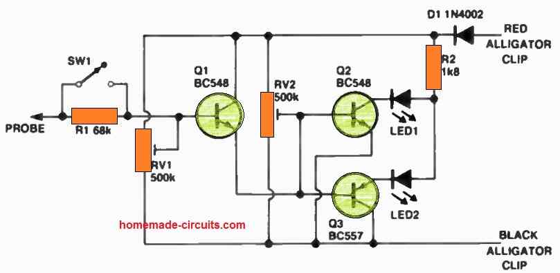
Initiate the circuit by switching ON connection between the circuit and a power source, ensuring that RV1 is set approximately halfway.
Gradually rotate RV2 until the 'high' LED illuminates, and then make a slight adjustment in the opposite direction until the 'low' LED lights up. Next, fine-tune RV1 until both LEDs are illuminated simultaneously.
In the event that the probe registers a high signal, Q1 and Q2 will become conductive, causing the 'high' LED to activate. Conversely, if the probe registers a low signal, Q3 will conduct, leading to the activation of the 'low' LED.
SW1 and R1 have been incorporated for situations where voltage levels exceed one volt.
2) Circuit Description (Using IC 4049)
The performance and characteristics of the probe can be understood from the following date:
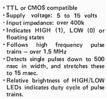
The logic probe circuit is built using inverter/buffer gates from a single IC 4049.
3 gates are used for making the main logic high/low detector circuit, while two are employed to form monostable multivibrator circuit.
The probe tip which detects the logic levels is connected with the gate IC1c through resistor R9.
When an input logic high or logic 1 is detected, the IC1c output turns low, causing the LEd2 to light up.
Likewise, when a LOW or logic 0 is detected at the input probe, the series pair IC1 e and IC1f light up LED1 via R4.
For "floating" input levels, meaning when the logic probe is not connected to anything, the resistors R1, R2, R3 make sure that the IC1c and IC1f are together held in the logic HIGH position.
Capacitor C1 attcahed across R2 works like a rapid action capacitor, which ensures that the pulse shape at the input of IC1e is sharp, allowing the probe to assess and track even the high frequency logic inputs over 1 MHz.
The monostable circuit created around IC1a and IC1b boost the pulses that are short (below 500 nsec) to 15 msec (0.7RC) with the aid of C3 and R8.
The input to the monostable is obtained from IC1c, while C2 provides the stage with the required isolation from the DC content.
In normal situations, the parts R7 and D1 enable the IC1b input to stay at a logic HIGH. However, when a negative edged pulse is detected via C2, the IC1b output is turned HIGH, forcing the IC1a output to become low and switch ON LED3.
Diode D1 makes sure that the IC1b input remains at a low logic level (over 0.7V), onle as long as the IC1a output stays low.
The above action inhibit repetitive pulses from re-triggering the input of IC1b, until the monostable is retriggered due to the discharging of C3 across earth via R8. This enables IC1a output to become logic high, turning OFF LED3.
The capacitors C4, and C5 which are not critical, safeguards the IC supply lines from possible voltage spikes and transients, emanating from the circuit under test.
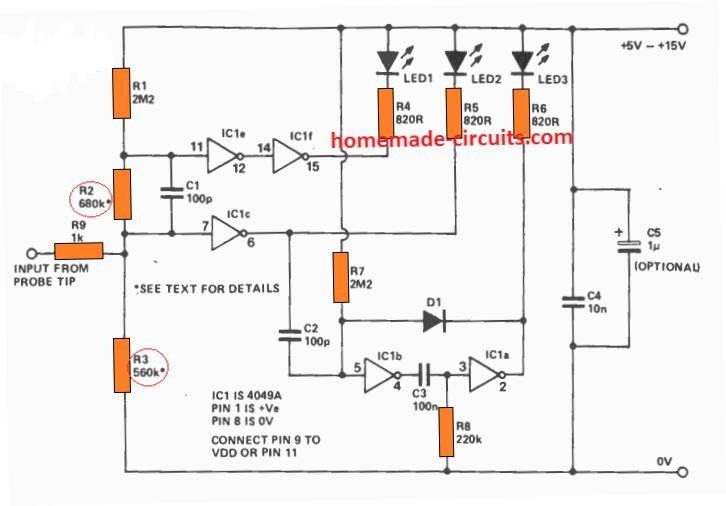
PCB Design and Component Overlay
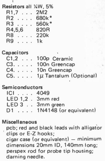
Parts List
How to Test
To test the logic probe working, connect it with a 5 V supply source. The 3 LEDs at this point should remain shut off, with the probe unconnected to any source or floating.
Now, the resistance R2 and R3 will need some tweaking depending on the response of the LED illumination as described below.
If you find LED2 begins glowing or flashing when powered, try increasing the R2 value to may be 820 k, until it stops glowing. However, LED 2 must glow when the tip is touched with your finger.
Also, try testing by touching the logic probe to the either supply rails which must cause the relevant LEDs to illuminate, and cause the PULSE LED to flash when the probe is touched to the positive DC line.
In this situation the LOW deyction LED must light up, if it doesn't then R2 may be a bit too large. Try 560k for it and check the corrected response by repeating the above procedure.
Next, try a 15 V supply as the supply source.Just as above, all the 3 LEDs must remain shut off.
The LED for HIGH detection might show a slight dim glow, while the probe tip is unconnected. However, if you find the glow noticeably high, you may try reducing the R3 value to 470 k, so that the glow is hardly noticeable.
But after this, make sure to check the logic probe circuit with the 5 V supply again, to ensure that the response is not altered in any manner.
3) Simple Logic Level Tester and Indicator Circuit
Here's a simpler logic level tester probe circuit that can be very useful device for those who may want to measure the logic levels of digital circuits frequently.
Being an IC based circuit, it's implemented in CMOS technology, its application is more dedicated to test circuits using the same technology.
By: R.K. Singh
Circuit Operation
The power for the proposed logic gate tester is obtained from the circuit under test itself.
However care must be taken not to put the power terminals in reverse, so when it is connected make sure to set the colors of each of the connecting wires.
For example: Red Color, for the cable that connects with the positive voltage (CN2) and black color to the wire that goes to 0 volts. (CN3)
Operational details of logic tester probe with IC 4001
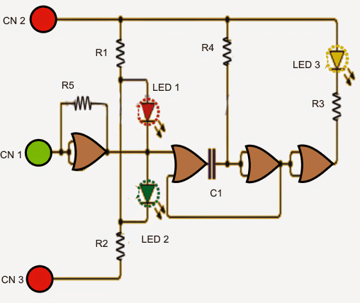
The operation is very simple. The 4001 CMOS integrated circuit has four two-input NOR gates, 3 LEDs and a few passive components used in the design.
Implementation also becomes crucial so that it is comfortable to apply while testing, therefore the printed circuit should be in the elongated in shape preferably.
Looking at the figure we see that the sensing signal is applied to CN1 terminal, which is connected to a NOR gate, whose inputs are in turn connected as a NOT gate or an inverter.
The inverted signal is applied to the 2 LEDs. The diode is switched depending on the voltage level (logic) at the output of the gate.
If the input is high logic level output of the first gate goes low activating the red LED.
Conversely if the detected is low, the signal is sensed is as a low level, the output of this gate is then rendered at high level illuminating the green LED.
In the event if the input signal is an AC or pulsing (varying voltage level constantly between high and low), both red and green LED light become on.
To acknowledge that a pulsed signal may be sensed, the yellow LED starts flashing here. This flashing is executed with the use of the second and third NOR gates, C1 and R4 which functions like an oscillator.
The oscillator output logic is applied to a 4th NOR gate connected as inverter gate which is directly responsible for activating the yellow LED via the given resistor. This oscillator can be seen continuously triggered by the output of the first NOR gate.
Circuit Diagram
Parts List for the above explained logic tester probe circuit
- 1 Integrated circuit CD4001 (4 2-input NOR gate CMOS version)
- 3 LEDs (1 red, 1 green, 1 yellow
- 5 resistors: 3 1K (R1, R2, R3), 1 2.2M (R5), 1 4.7M (R4)
- 1no capacitor: 100 nF
4) Logic Tester Using LM339 IC
Referring to the next simple 3 LED logic probe circuit below, it is built around 3 comparators from the IC LM339.
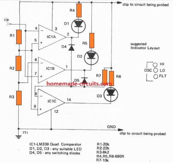
The LED indicate 3 different conditions of the input logic voltage levels.
The resistors R1, R2, R3 work like resistive dividers, which help to determine the various voltage levels at the input probe.
A potential higher than 3 V causes the output of IC1 A to go low, switching ON the "HIGH" LED.
When the input logic potential is less than 0.8 V, the IC1 B output becomes low causing the D2 to light up.
In case when the probe level is floating or is not connected to any voltage, causes the "FLOAT" LED to illuminate.
When a frequency is detected at the input, turns on both the "HIGH" and the "LOW" LEDs, which indicate the presence of an oscillating frequency at the input.
From the above explanation we can understand that it is possible to tweak the detection levels of the input logic voltages simply by tweaking the values of R1, R2, or R3, appropriately.
Since the IC LM339 can be work with supply inputs up to 36 V means this logic probe is not restricted to TTL ICs only, rather can be used for testing logic circuits right from 3 V to 36 V.


Questions & Answers
Hello Swagatam,I really love your website. I made a little pcb with the logic probe using a LM339 as suggested. Although very logical I struggled with the floating indicator. Instead of showing the floating LED D3, D1 was permanently on in floating mode. After some tweaking around, I happen to fix this by attaching a 10M resistor from probe to ground. The hint came from neufeld.newton.ks.us/electronics/?p=31. He connected a 100M to GND and a 200M to VCC.
Best, Phil
Thank you so much Phil, Glad you could solve the issue with a simple fix.
All the best to you!
Cheers!
For your post on the 4049 tester here, you say to use green caps, mylar? I have a batch of mylar caps with code on them. For the 100nF which is 104 this matches the standardized code, for the 10nF caps in the batch I have it indicates those are code marked 2A562J which doesn’t make sense to me. If 100nF is 0.1uf and 10nF is 0.01 how can the code be 562J? Wouldn’t a standard MLCC be fine to use in all the positions aside from the tant 1uF which could be a 105 MLCC. Also I take it the ABCDE are to be jumpered to the corresponding letters as the board is space limited?
Yes, you can use any standard MLCC capacitors except for the tantalum. You are also correct regarding the points ABCDE which must be connected using jumper wires to their respective points by referring to the circuit diagram.
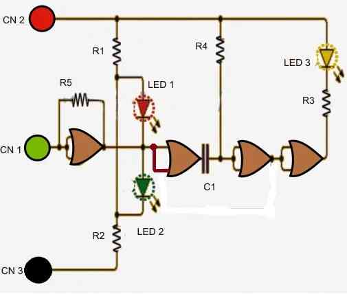
I assembled a logic tester from a CD4001 but I don’t think it works the way it should. It does detect a H and L at the input and there is a yellow LED that is supposed to indicate a pulse, the yellow is lit all the time as is with the red and green LED’s but if the input is H the green LED goes out which is correct, if the input is L the red goes out which is also correct. I don’t have a current pulsating source circuit to test the yellow as of yet but I guess I need to rig up something. I like this 339 circuit as it has a much higher voltage tolerance so I think I will give it a try. I did add a schottky diode on the positive power lead as a polarity protection in this 4001. Before I did that, the yellow LED only lit if the input was made to pulse by touching the probe to either Hor L in tapping, then when I added the diode it stopped doing that. I bypassed the diode with a but that didn’t change the way the circuit worked as if to return it to the state when it worked like I guess it should have. I also found a variation of the 4001 which only used 5 R’s instead of the 7 my circuit has and mine is supposed to have a piezo for audio. I like that part as it is connected to the part of the circuit for the pulse indication. Also for the yellow LED section there are differences in that 4001 circuit and these using the 4049 and 4001. Do you have any insight? Why is my tester not working like it did before and is it working as it should at all. It does tell me if the input is H or L but now the yellow stays on all the time even if I tap the input to either H or L, it doesn’t flash anymore.
The yellow LED should not be lit all the time according to me. Because the presence of R4 will cause the output of the last NOR gate to be high all the time. If the output to the cathode of the yellow LED is high then it should remain shut off. You can do one modification to the existing circuit as shown in the following image and see the response. Remove the feedback connection across the middle two NOR gates and make a short across the two inputs of the second NOR gate:
good,after noon , hope family ok ,,take care
Yes, we are all safe just as you are, thanks!