• Skip to main content
  • Skip to primary sidebar

Homemade Circuit Projects

Get free circuit help 24/7

Circuits for Beginners | Basic Circuits | LED Driver | Hobby Circuits | Transistor Circuits

New-Projects | Privacy Policy | About us | Contact | Disclaimer | Copyright | Videos

You are here: Home / Home Electrical Circuits / Transformerless Relay Driver Stage

Transformerless Relay Driver Stage

Last Updated on March 8, 2019 by Swagatam 8 Comments

ask questions through comments

In this post we discuss an enhanced transformerles power supply circuit design which consists a well stabilized and regulated DC stage along with a relay driver stage which operates through an external pulse. he idea was suggested by Mr. Reza.

Technical Specifications

Reza: Dear Sir, I have a problem with one Circuit regarding converting an Ac 110v power supply to 220v or 250v AC. But I am unable to do it.

You’re Blog Site and your Circuits make Me crazy, really you are an Electro Man. My Interest is growing  more and more with every visit to your site. This has inspired me to solve my problem with your help.

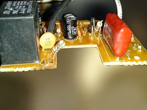
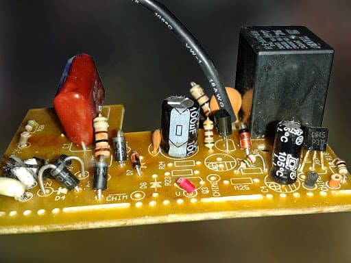
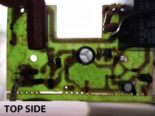
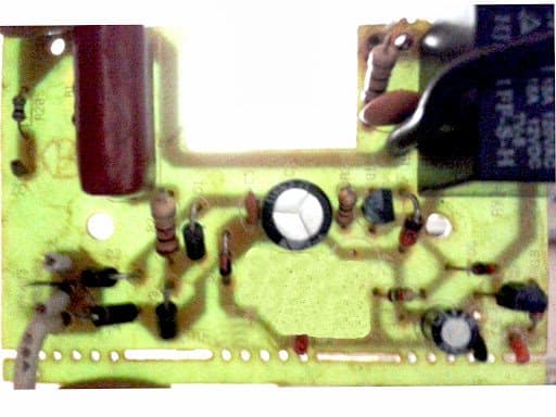
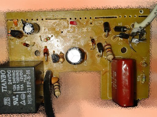
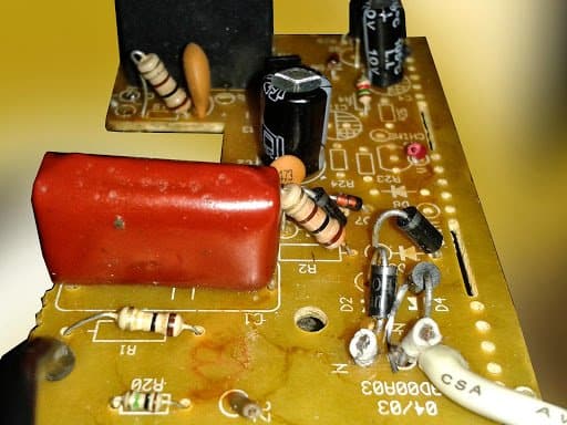
So, I need to send you some pictures of that circuit which I want to convert from AC 110v to 220v up 250v AC Main Line.

Sir I am waiting for your response. Simply should I change the 105-250v Capacitor and two Resistors that are 100kΩ and 100Ω or something more than that.

But I am confused regarding what is the real one for 220v up to 250v. For your information I have changed the 200watt Halogen Bulb too.

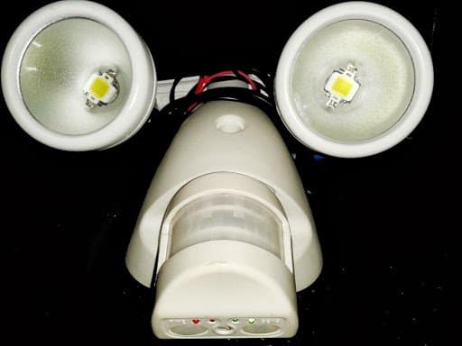
I have used two square sizes LED (Per Bulb head) and the extra 5volt Mobile Charger Adapter power source for my LEDs, and connected with RL1.

My Response:

Can you specify what exactly are you trying to build?

Reza: I am building nothing. Trying to convert my 110v motion sensor device to220v AC. That's all
But I am not sure with the procedures. That's why i need your help sir, it is transformerless power circuit board.

Circuit Operation:

Before we modify the design for 220V application, let's first understand the functioning of this upgraded transformerless power supply with relay changeover trigger circuit through the following discussion

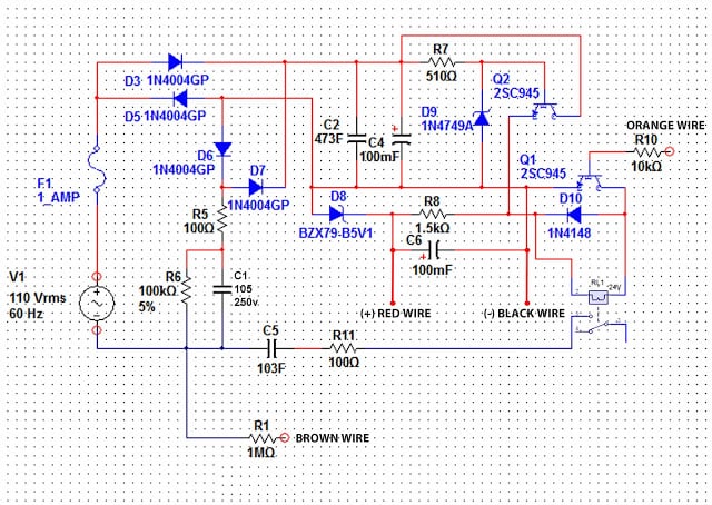
Referring the diagram given below, the various parts can be categorized with the following operations:

C1 = High voltage capacitor for stepping down the mains current to tolerable circuit limits.
D3, D5, D6, D7 form the basic bridge rectifier stage.

C2, C4 are for filtering the spikes and the ripples from the DC components.

Q2 forms the emitter follower with its base clamped at 24V by the zener diode D9 and R7.

Being an emitter follower, the voltage at emitter also will be equal to the base voltage, that is 24V and current equal to the combined value of base and collector.

This +24V emitter output is applied to the 24V relay via Q1. When Q1 is triggered from an external positive source via R10 (orange wire), the relay activates.

R8 and D8 connected to the emitter of Q2 forms an additional 5V stabilized output, may be for some specified purpose across the shown RED wire.

R5 is used for included for restricting switch ON surges, while R6 for discharging C1 whenever the system is unplugged from mains.

Modifying the Circuit for 220V Operation

As requested by Mr. Reza, the circuit needs to be modified so that it can safely operate even with 220V supplies, however a close look reveals that except C1 voltage everything seems to be in order and well suited for voltages right from 110V to 300V.

So, C1 should be changed to 105/400V, and may be R7 should be tweaked a bit or its wattage increased to some higher level and R6 raised to 1M, rest everything looks perfect and well organized.

Circuit Diagram
get free help for circuit diagrams

You'll also like:

  • 1.  0-40V Adjustable Power Supply Circuit – Construction Tutorial
  • 2.  Low Dropout (LDO) Voltage Regulator IC KA378R12C – Pinout and Working Specs
  • 3.  Heater Controller Circuit Using Push-Buttons
  • 4.  Mosquito Killer Circuit with Window Trap
  • 5.  Climate Dependent Automatic Fan Speed Controller Circuit
  • 6.  Surge Protected Cheap Transformerless Hi-Watt LED Driver Circuit

About Swagatam

I am an electronic engineer (dipIETE ), hobbyist, inventor, schematic/PCB designer, manufacturer. I am also the founder of the website: https://www.homemade-circuits.com/, where I love sharing my innovative circuit ideas and tutorials.
If you have any circuit related query, you may interact through comments, I'll be most happy to help!

Subscribe for the Latest Posts


Reader Interactions

Comments

    Have Questions? Please post your comments below for quick replies! Comments should be related to the above artcile Cancel reply

    Your email address will not be published. Required fields are marked *

  1. sedigh hosein says

    September 5, 2019 at 4:35 am

    hi swagatam i dont know thate weither my comment are visible for you ???

    Reply
    • Swagatam says

      September 5, 2019 at 9:44 am

      Hi Sedigh, once the comment is posted it will reach me without fail, so you can rest assured you will get the replies.

      Reply
  2. sedigh hosein says

    September 5, 2019 at 4:28 am

    hi dear sir swagatam majomdar i would like to know most about transforless circuits for using to atmaga chip with fully protection and also useing an ic 7805 in outlet circuit excuse me concern poor english
    weather you can suggest me an circuit about this
    with best regards

    Reply
    • Swagatam says

      September 5, 2019 at 9:45 am

      Hi Sedign, I am sorry I do not have this circuit presently using Atmega chip

      Reply
  3. sedigh hosein says

    September 5, 2019 at 4:08 am

    hi swagatam majomdar can i use of an 7805 in output the circuits that are transforless???

    Reply
    • Swagatam says

      September 5, 2019 at 9:47 am

      Sedign, a 7805 can be applied after a 24V zener diode, or through a MOSFET regulator

      Reply
  4. Shrikant Dhone says

    December 16, 2015 at 5:13 pm

    Hi swagatam
    I constructed the ckt for 24v relay but it works only for few minutes
    what is the reason. most of the ckts work only for few minutes
    i used 1n4007 diodes
    please help me

    Reply
    • Swagatam says

      December 17, 2015 at 11:06 am

      Hi Shrikant, It'll be difficult for me to judge the fault without actually seeing it, can you tell me what exactly are you trying to build or implement with the design? I could suggest an alternative and easier circuit.

      Reply

Primary Sidebar


Categories

  • 3-Phase Power (15)
  • 324 IC Circuits (19)
  • 4017 IC Circuits (52)
  • 4060 IC Circuits (25)
  • 555 IC Circuits (98)
  • 741 IC Circuits (19)
  • Amplifiers (59)
  • Arduino Engineering Projects (83)
  • Audio Projects (94)
  • Battery Chargers (83)
  • Car and Motorcycle (94)
  • Datasheets (46)
  • Decorative Lighting (Diwali, Christmas) (32)
  • DIY LED Projects (89)
  • Electronic Components (97)
  • Electronic Devices and Circuit Theory (35)
  • Electronics Tutorial (109)
  • Fish Aquarium (5)
  • Free Energy (34)
  • Fun Projects (12)
  • GSM Projects (9)
  • Health Related (19)
  • Heater Controllers (28)
  • Home Electrical Circuits (100)
  • How to Articles (20)
  • Incubator Related (6)
  • Industrial Electronics (28)
  • Infrared (IR) (40)
  • Inverter Circuits (98)
  • Laser Projects (12)
  • LM317/LM338 (21)
  • LM3915 IC (25)
  • Meters and Testers (64)
  • Mini Projects (156)
  • Motor Controller (66)
  • MPPT (7)
  • Oscillator Circuits (24)
  • PIR (Passive Infrared) (8)
  • Power Electronics (33)
  • Power Supply Circuits (74)
  • Radio Circuits (9)
  • Remote Control (47)
  • Security and Alarm (61)
  • Sensors and Detectors (118)
  • SG3525 IC (5)
  • Simple Circuits (74)
  • SMPS (29)
  • Solar Controllers (60)
  • Timer and Delay Relay (53)
  • TL494 IC (5)
  • Transformerless Power Supply (8)
  • Transmitter Circuits (40)
  • Ultrasonic Projects (14)
  • Water Level Controller (45)


Circuit Calculators

  • AWG to Millimeter Converter
  • Battery Back up Time Calculator
  • Capacitance Reactance Calculator
  • IC 555 Astable Calculator
  • IC 555 Monostable Calculator
  • Inductance Calculator
  • LC Resonance Calculator
  • LM317, LM338, LM396 Calculator
  • Ohm’s Law Calculator
  • Phase Angle Phase Shift Calculator
  • Power Factor (PF) Calculator
  • Reactance Calculator
  • Small Signal Transistor(BJT) and Diode Quick Datasheet
  • Transistor Astable Calculator
  • Transistor base Resistor Calculator
  • Voltage Divider Calculator
  • Wire Current Calculator
  • Zener Diode Calculator


You can also Chat with me here:

Facebook
Twitter
YouTube
Instagram
My Facebook-Page
Quora


© 2022 · Swagatam Innovations

We use cookies on our website to give you the best experience.
Cookie settingsAccept All
Privacy & Cookies Policy

Privacy Overview

This website uses cookies to improve your experience while you navigate through the website. Please visit the Privacy Policy Page for more info.
Necessary
Always Enabled
Necessary cookies are absolutely essential for the website to function properly. This category only includes cookies that ensures basic functionalities and security features of the website. These cookies do not store any personal information.
Non-necessary
Any cookies that may not be particularly necessary for the website to function and is used specifically to collect user personal data via analytics, ads, other embedded contents are termed as non-necessary cookies. It is mandatory to procure user consent prior to running these cookies on your website.
SAVE & ACCEPT