Hi Friends, I am Swagatam. Most readers know me through homemade-circuits.com, a website I started in 2011 to share practical electronics knowledge with hobbyists, students, and working engineers.
Some people also know me by the name Swag, Swagat, Sagar…

I completed my electronics studies at DIPIETE in 1994 and since then I have spent decades working hands-on with electronic circuits, learning how they actually behave beyond textbooks, you only learn that by doing.
About homemade-circuits.com
I started homemade-circuits.com with a simple goal, to make electronics concepts easy to understand and genuinely useful for people who want to learn and build circuits themselves.
Before this site, I worked as an electronic circuit content writer at Brighthub. Then in the year 2013, I started the site homemade-circuits.com.

How This Site Is Different
On homemade-circuits, I personally read and reply to comments. Over the years, I have answered more than 50,000 circuit-related questions, helping readers troubleshoot problems and improve circuit designs, step by step.
Many circuits published here get refined through these discussions, becoming more reliable and practical over time.
A Bit More About Me
Outside electronics, I am an animal lover. I have rescued dogs, cats, and birds, and one long-term goal is to build a shelter for injured and abandoned animals, still working towards that.
Stay Connected
If you need help with any circuit on this website, post your question under the relevant article. I always try my best to provide clear and practical guidance based on experience.
Thank you for visiting homemade-circuits.com. I hope this site helps you learn, build, and troubleshoot electronic circuits with confidence.
Our Esteemed Engineers who helped this site to grow with their Valuable Contributions:
- R. Girish
- Abu Hafss
- Ali
- ERSA
- Robin Peter
- Selim Yavuz
- Ainsworth Lynch
- Vasilis K
- Syed Asim
- Henry Bowman
- SS Kopparthy
- Ajay Dusa
- Ankit Negi
- Navneet Sajwan
- Valerian Meyers (Val)
- Swagatam
- Matrix
Some important names could be missing here, if you think your name deserves to be here please inform us through a comment or through the contact page, we'll update it immediately.
Questions & Answers
hi. I like your 10w MOSFET amplifier first drawing. can you give me permission to use it in a technical book?
Sure, you can use the diagram, just credit my site.
(1). I need a circuit design to amplify the output signal for a pnp Proximity sensor
( 2). I also need a design for an inverter circuit for 24 volts dc to 380 volts ac that will be able to drive a 2.2hp induction motor thanks
For the first requirement, you can try the following concept:
For the 2nd requirement, you can try the following concept:
Add more mosfets in parallel for 2.2hp load
Hi Swagatam, I have a problem with a Duracell AA/AAA NC-HM battery charger. It doesn’t automatically disconnect from the charger, even after charging the batteries for 4 hours, even when they’re sufficiently charged. The charger has a CD4541 integrated circuit. Can you help me understand how the automatic disconnect circuit works? Thanks.
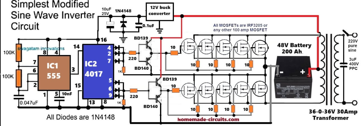
Hello Swagatam, I am Waiyaki Kanongo from Uganda. I am very interested in your inverter circuit designs. You are one of the kind that takes time to genuinely explain in details about the inverter circuits you design. I have earned a lot from your projects, thanks to God for the knowledge he gave you. However, would I would wish to design a simple and yet powerful Sine wave inverter that could drive at least a 1500Watts transformer using a 12V battery. Will be delighted to hear from you soon.
Thank you Waiyaki, I am glad my circuit projects helped you to learn more.
For a 1500 watt inverter, the 12V will be too less and demand very high current, so I won’t recommend it.
Instead, you can use two 12V batteries in series. Even then the battery will be need to be 1500 / 24 = 62.5 * 5 = 312 Ah, that looks unpracticable.
For a simple design, you can try the first circuit from the following article.
https://www.homemade-circuits.com/make-this-1kva-1000-watts-pure-sine/
Hi Lazaro,
The IC CD4541 is a programmable timer IC, so it could have been programmed to disconnect the battery after a preset time interval, it is not designed to sense the battery charge level and then cut off..
Good morning my friend, how are you? I’m looking for a way to get the schematic for the battery charger as you requested, and I’ve been thinking of another option! I can send you the model number and brand of the charger, and you can access the electrical diagram much better than I can. My internet speed is very limited here on the island. The brand of the charger is (ENERCELL), and the only interesting detail is a number: 23-786
Good morning friend, I tried to find the schematic of this charger, but unfortunately it seems the manufacturer has not uploaded any schematic for this product.
Hmm, and I thought there was another electronic disconnection option. So, if the circuit is pre-programmed to charge the batteries in 8 hours and then cuts off the charge to prevent overcharging, could it fail under that design concept? Because if, by chance, the charger is disconnected from the 1110V power line, or the power goes out in the house for some reason, and when the power comes back on, the battery charger could start from scratch again, counting another 8 hours of charging from that point. This would result in overcharging the battery and its subsequent destructive effect, causing it to catch fire. Sorry, but that’s just common sense; it’s a very real possibility that could happen in any situation in the life of a user with that design! Doesn’t that seem logical? Thanks for your answers.
Yes, you are correct, using a timer as a cut-off for battery charging does not make sense and can be dangerous for the battery health.
Thank you, my friend, for your attention and humble attitude. I would like to count on you for future instruction. I am Cuban and live in Cuba. I would be very grateful to have your support in my personal development in electronics. I make a great effort to communicate with you; I have to use Google Translate to write to you because my English is very poor. My native language is Spanish. Internet access is very difficult in my country, as is obtaining resources for electronics, especially tools. Thank you, my friend, I am truly grateful! Furthermore, I would like your opinion on some measuring instruments I am considering purchasing. I have no idea about their quality. Could you help me with your expertise and knowledge? I want to know if they are good, bad, or average. Thank you in advance.
No problem My friend, I can definitely understand your problems.
Your Google translate is perfect and I can completely understand your translated version.
I would recommend Amazon for buying the tools, because by far Amazon is very strict with its product quality, and 95% of the time the quality will be good.
Feel free to comment and ask questions if you have any doubts regarding any topic, i will be happy to help.
You can also comment under my youtube channel…
Thank you for your response and time, but I must inform you that I live in a country with a communist system. It’s an island, and I can’t access Amazon; there’s no Amazon here, nor any other capitalist site to buy things. To buy any tool, I have to go through intermediary sellers who can travel and access these products directly in other countries. They then legally bring them into the country and resell them at different prices. I’m explaining this because I’d like your opinion on these multimeters, for example:
Aneng 621A Multimeter
Aneng 870 Multimeter
SOYI ZT-702S Oscilloscope Multimeter
I imagine they’re of Chinese origin, but I don’t know their quality. Could you tell me about them? Thank you…
OK, now I understand your real problem.
In that case, you can go for those Chinese products, they are cheap and reasonably good, however they will need some careful handling and maintanence….so you can buy those Chinese items, they will work nicely, but only as long as you maintain them and handle them softly with proper care…
hello Hi my friend, how are you? I have no idea how to send an electronic schematic this way. I don’t know how to do it. Could you show me? Regards…
Hi Lazaro,
No problem, I will explain you how to do it…Please open your Google drive, upload your schematic there, and send me the link here, I will check it.
Make sure the link is in the “shared mode”, otherwise I will not be able to open it…
Gracias amigo, siempre es muy util tus valoraciones, gracias gracias, mantenemos comunicaciones…
Good morning Swagatam, I hope you are well. I’m going to bother you once again. I’ve had this repair project pending for a long time and I forgot to mention it to you. I need your expertise once more to clear up a doubt I have. I was repairing an Enercell AAA, AA NCd-Hm battery charger, model number [number missing]. Well, this is what the sticker on the 23-786 charger says. I don’t know if I can send you a picture of the model. Again, the brand is ENERCELL, and for some reason, the power supply stage suffered a failure. The Zener diode connected to the oscillator driver broke, causing the voltage to rise above the design limit. As a result, two integrated circuits were damaged. One is an LM324, which I was able to find as a replacement. The other integrated circuit is an L5568. Above the numbers, it has the name ZAMYA printed on it. The difficult and strange thing is that I can’t find any information about this integrated circuit on datasheet websites, and even less so here in Cuba. Could you help me find information about this integrated circuit? Again, it’s the L5568 IC, and above the number, it has the name ZAMYA. I would like to be able to repair it. The charger with some equivalent of that IC, thanks in advance….
Good Evening Lazaro,
The L5568 IC with ZAMYA marking is not a standard IC and looks like a custom charger controller used only in that specific unit. Unfortunately there is no datasheet or direct replacement available for it.
Since it got damaged due to a Zener failure, then best practical approach would be either to redesign the power supply using a standard SMPS IC like UC3842/UC3843 or bypass the internal SMPS and use an external regulated DC supply.
If you can draw and provide me a rough circuit diagram, then I may be able to understand the fault and suggest a workable replacement solution.
Sure friend, no problems at all…wish you all the best…
Feel free to contact if you have any issues with any of the circuits….
Swagatam,
I need an LC filter circuit for 12VDC 100A, roughly, specifically an automotive-type dual cooling fans. To eliminate any power spikes or backfeeding into any sensitive electronic devices, similar to an AM radio, an 8-track player or 2 cans on a string. Would it have to be rated to handle the higher voltage/current spikes? Similar to a water hammer (reflecting shock wave) in a pumping system, which uses a pressure relief valve to dump the shock to the ground.
Several commercial units start the fans at 40-60%, then ramp the speed up according to the temperature sensors. At $150.00 to 300.00 each.
I’m looking for a simpler way to filter out any spikes when the sensor provides a ground for the relay coil and starts the fans.
Minimal cost for a relay, filter circuit, temperature sensor and fan. Hopefully less than the variable controller.
It wouldn’t be as simple as the damping circuit for a relay coil? That would be a capacitor or a resistor?
I use dual radiator fans(40-100a locked rotor amps, each),
A 40-100 amp fan on the transmission cooler. This is only 3 fans. Other than the hvac fan. That’s only about a 15a fan.
These are starting amperages, and hopefully, they would not all run at the same time.
I’d have a 250a to 300a (hot) charging system. I.E. Most charging systems are rated Cold. I know you know, but other readers might not.
Thank you for any help.
Hi Bob,
The main problem is not the relay coil, but the high locked rotor surge and brush noise from the DC fan motors. A 100A LC filter may not be good because the inductor must handle full load and surge current without saturating, which makes it large and costly.
Instead I would recommend the following
Add a flyback diode across each relay coil.
Put an automotive TVS diode across the 12V line near the fans to clamp spikes.
Add an RC snubber across each motor (for example 0.1uF in series with 1–2 ohm).
Place a large low ESR electrolytic capacitor (2200uF to 4700uF, 25V+) near the fan supply.
Use thick wiring and proper grounding directly to battery negative.
If possible, stagger up the fan startup.
This will be much cheaper than a variable speed controller and should reduce most spikes and interference.
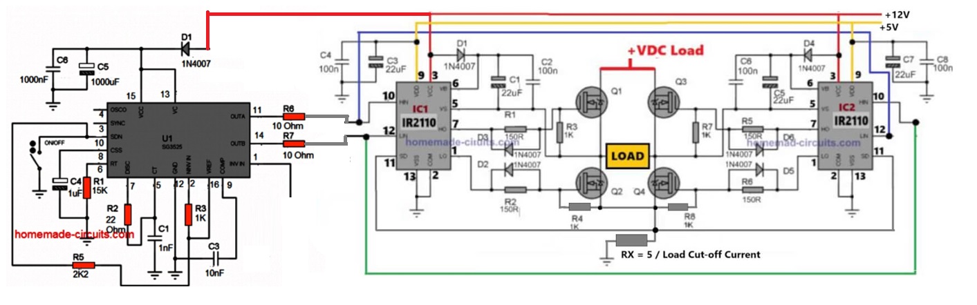
Hi Swagatam. Thank you so much for offering up such wise and useful circuitry information. I’m looking for a power inverter circuit that is rated for 300W, 24VDC input, 120VAC/60hz pure sign wave output with short circuit protection and/or a current limiting output so that excess load on the output will not damage components but will shut down or clamp the output. I would also like to have the main power transistors be oversized so a heatsink is not necessary for them. Do you have a circuit already designed that does this. Thank you so much.
Thank you Nathan, that can be quite easily accomplished using a SG3525 IC.
Can you please tell me, whether your transformer is a 3-wire center tap or just two wire unit? I will try to figure out the design…
transformer would be two wire
OK, here’s one design you can try, but it is a square wave design, once you build and test it successfully, after that it can be easily converted into sine wave using 555 PWM processors, i will explain that once you finish testing this:
Happy 2026. I’m from Uruguay, a Latin American country. I cloned your site for my personal use, to learn using HTTRACK. I congratulate you on your work; I found solutions and circuits even for an old laptop that needed a 15-volt, 3-amp charger. I would recommend that you save your entire site as a .rar or .zip file on Archive.org, a US-based site that stores all kinds of data for free and forever, as long as it doesn’t contain passwords or viruses. It’s 100% free and permanent, and it was founded by someone who, through donations, has turned it into a library of Alexandria. There I found a circuit with a single transistor for a battery-free radio beacon for marine use. It’s powered by air currents. It’s a circuit from 1965 and is in Czech. I haven’t translated it yet, but when I do, I’ll upload it to Archive.org in both Spanish and English with the title: Battery-Free Radio Beacon, 1 Transistor. Well, thank you very much from Montevideo, Uruguay. Sincerely, Alex Rademaker. Electronics student. 60 years old, but always young at heart.
Thanks you so much Alex, for your kind words, and interesting suggestions… it is much appreciated.
I will definitely consider your suggestions…all the best to you.
Cheers, and a Happy 2026 to you too!
hello sir..l need final year projects. that can be defendable, less cost and practical.
electrical and electronics engineering
Godfrey, please give some examples, then I can suggest..
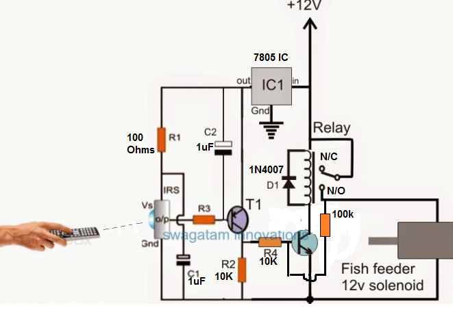
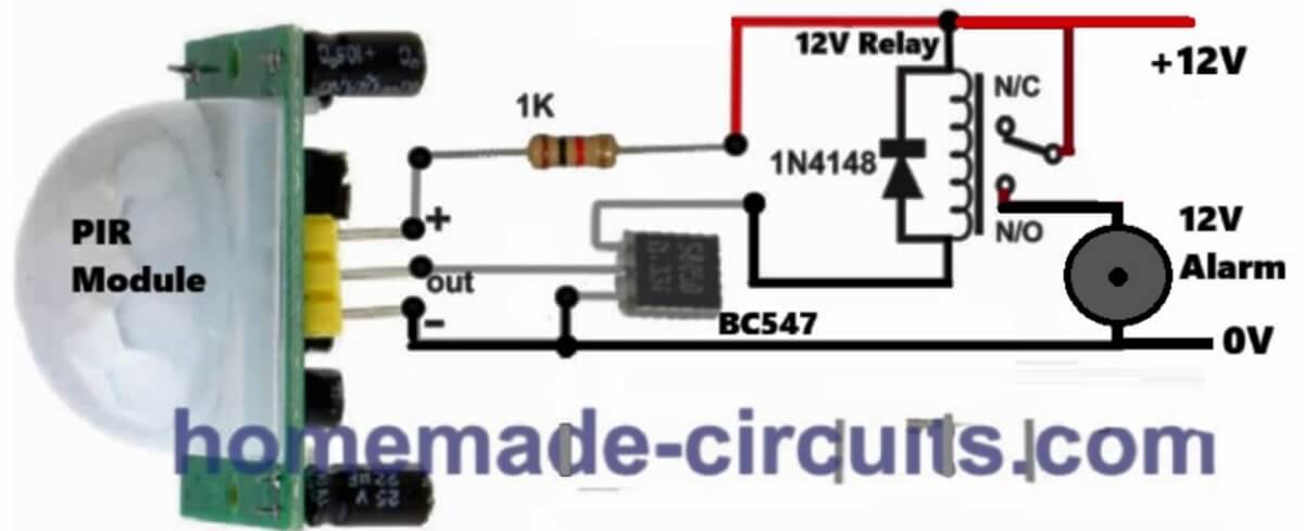
Hi, my name is Umilghaniyu, I’m student.I want you to help me with a circuit that works like this: a lamp that stays dim when there is no motion, and shines full bright when it detects motion. Please help me with the components I will use as well.
Hi, you can use the following PIR based circuit for your application and configure the relay contacts for making the lamp dim or bright…
I want to build turn indicator flashing lights for my (pedal) cycle using one or two 3.7v lion cells for power. I have tried this with a 555 and lots of different LEDs but none of my attempts have been bright enough to be seen in traffic in the sunshine. I wondered whether it would be posssible to overload the LED for a very brief bright flash, using perhaps a capacitor, without killing the LED?
Can you suggest a circuit for this? Many thanks for any response. I am in UK.
A 555 flasher circuit can produce awesome amount of light with good quality high bright LEDs, however a standard 555 IC may not work properly with a 3.7V cell. So actually there’s no need of any external capacitors…..
So now you can try a BJT astable flasher instead and check the results:
https://www.homemade-circuits.com/how-to-make-any-light-strobe-light/
Thanks so much for giving your time and expertise. I will try out your strobe-light circuit and let you know what happens.
Thanks Swag, I may have asked you a million doubts, but still quick replies are your mode of helping someone. You may have aspired young electronic engineers (exclude me). It would be of great help for someone who wants quick answers for doubts they need to solve. Certain sections like “Home Electrical Circuits”, “Health related Projects”, “Inverter Circuits” and ” Indicator Circuits” etc. are some of the most helpful sections ever. And I am in a great debt to you for desulphating a battery with your magic circuit and the number of questions you answered in it. I hope this community may thrive and become bigger. And as for the lead-acid battery, it is revived. I must thank you extremely for this
Thank you Anto, for your kind words…it is much appreciated, glad my suggestions helped you to solve your circuit problems…
Is it forbidden to upload your circuits to YouTube?
Yes, it is forbidden, you cannot upload copyrighted work on youtube or anywhere else…