The LM10 is a pioneering operational amplifier designed to operate from single ended power inputs with voltages as low as 1.1V, and up to as high as 40V.
As can be witnessed in Figure 1, the device consists of an op amp, a precision 200 mV band-gap voltage reference, and a reference amplifier, all encased inside a single 8-pin bundle.

In this post we take a peek at an entire heap of functional application circuits using the device LM 10.
Basic LM10 Configuration
The basic configuration for an LM10 op amp is shown in the following figure:
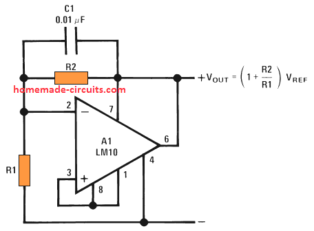
In the above circuit we can see that the LM10 is connected in a quite an unusual way, which is different from other op amps.
Here, the output is connected with the positive line which means it shunts or shorts the positive line with ground depending on a given input threshold detection.
This also implies that, in this shunt regulator mode, the positive to the op amp must be supplied via a resistor.
The pin3 which is the non-inverting input of the op amp is connected with a fixed reference voltage of 200 mV through the reference pinouts 1 and 8 of the IC.
Thus, pin3 being set at a fixed reference, the pin2 now becomes the detector input of the op amp and can be used for detecting a desired voltage threshold from an external parameter.
All the LM10 application circuits I have explained below are based on the above explained fundamental shunt mode.
LM10 Op Amp Precision Voltage Regulator Circuits
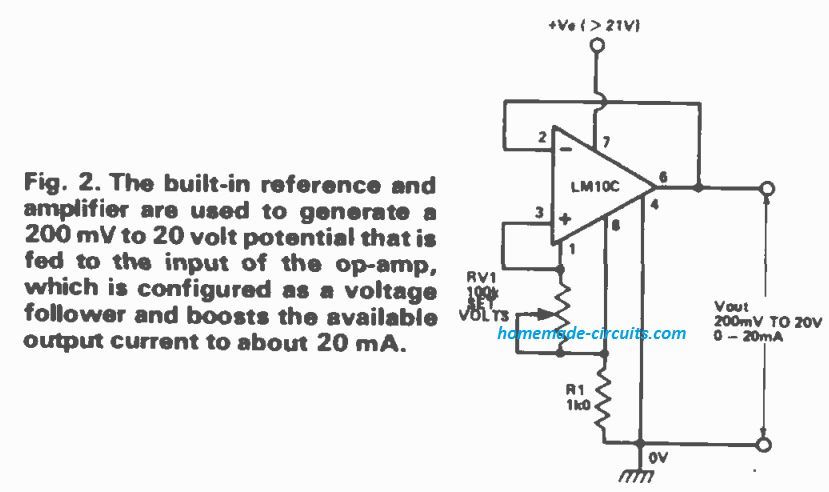
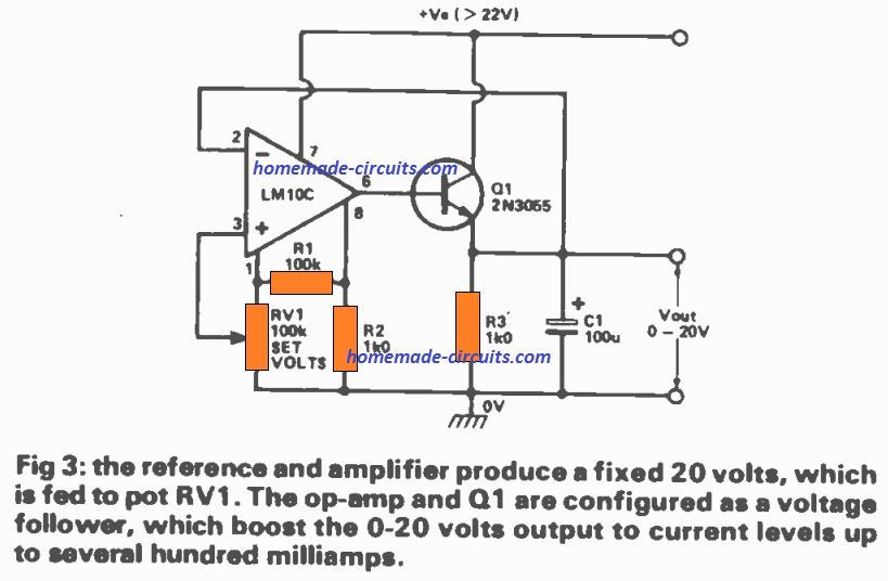
The LM10, due to it's built-in precision voltage reference and op -amp, becomes best suited for voltage regulator applications. Figures 2 to 9 exhibit several practical circuits of this variety.
200 mV to 200 V Reference Generator: The IC's built-in reference and amplifier are accustomed to create a 200 mV to 20 volt voltage levels which is applied to the op amp input, set up like a voltage follower and enhances the available output current to around 20 mA.
0 to 20 V 1 Amp Variable Regulator: In Fig 3 the internal reference and amplifier develop a fixed 20 volts, which is applied to pot RV1 . The op-amp and transistor Q1 are wired like a voltage follower to amplify the output of 0-20 volts to current with magnitudes close to many hundred milliamps.
Fixed 5 V 20 mA Regulator: In Fig 4 the op-amp input is extracted straight from the 200 mV reference, to provide a 5 volt output.
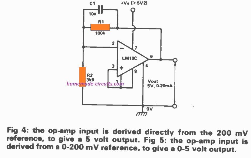
0 to 5 V Regulator: In Fig 5 the op-amp input is acquired setting up an internal 0-200 mV reference, to produce a 0-5 volt output.
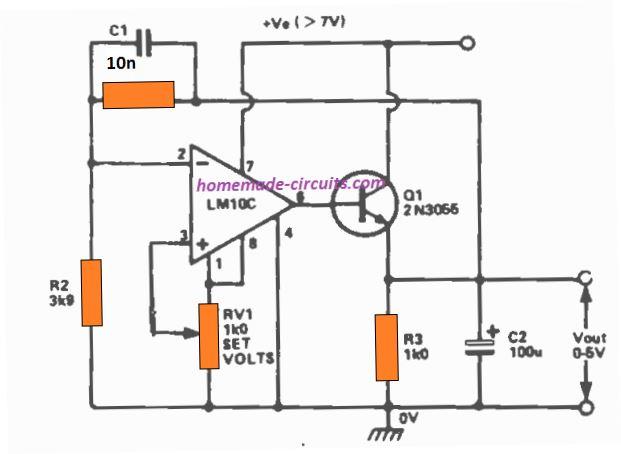
50 V to 200 V Variable regulated Supply: Figures 6 and 7 demonstrate the way the LM 10 could be employed in the 'floating' manner, to produce high output voltages. Be aware in each of these circuits the IC is applied in the 'shunt' mode through load resistor R3, such that just a small amount of volts are created across the LM 10 itself.
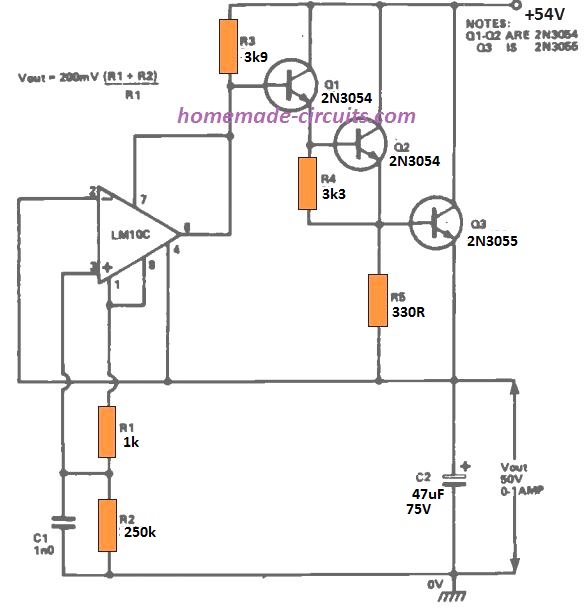

Simple Lab Power Supply: The above concepts can be further upgraded to built a full fledged 0 to 50 V adjustable laboratory power supply as shown below.
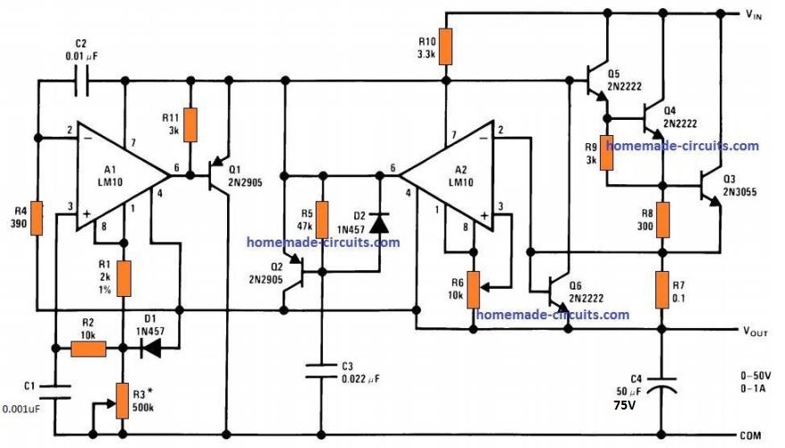
An output short circuit protected version of the above 250 V regulator can be witnessed in the following diagram

5 V Shunt Regulator Circuit: A straightforward illustration of the LM 10 application in a 5 volt shunt regulator.
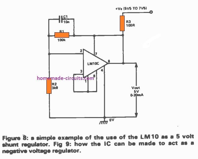
The below Fig 9 shows exactly how the IC could be configured to work as a negative voltage regulator.
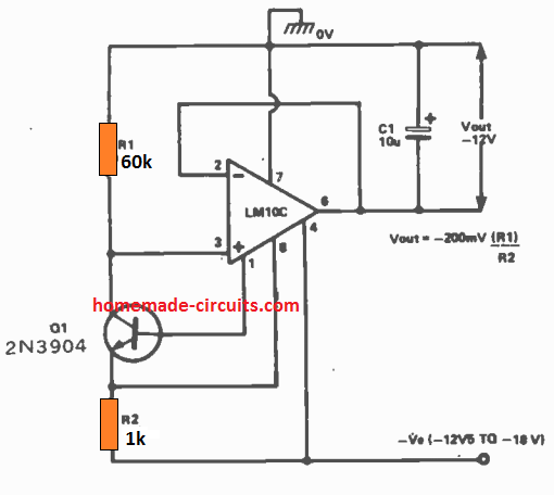
LM10 Precision Voltage/Current Monitor Circuits
The LM10 also works well in a variety of voltage, current, and resistance dependent error indicator circuits with audible or visual signals.
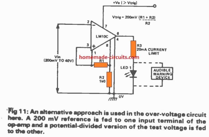
Figures 10 to 23 exhibit these types of designs. In Figures 10 to 1 7 circuits, the op amp is employed as a basic voltage comparator, having its output driving either a LED pointer or an audible alarm unit through an appropriate current limiter resistor.
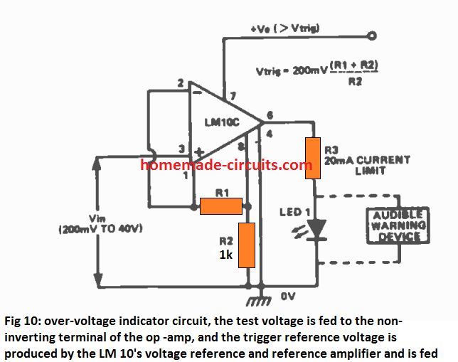
Over Voltage Indicator: In Fig 10 above the IC LM10 is configured as an over-voltage indicator circuit. The sensing voltage is applied to the non-inverting pin#3 of the op-amp, and the reference voltage at pin8 is generated by the LM10's internal voltage reference and reference amplifier and is supplied to the inverting pin#2 of the op -amp.
The above design could be also configured in the following alternative manner, which will also serve to indicate an over voltage condition
The Fig 11 below shows different strategy is employed in the over-voltage indicator circuit here. A 200 mV reference is applied to one input pin of the op amp and a resistive divider variation of the test voltage is applied to another.
An Under voltage Indicator circuit shown in the following Fig. 12 works with the same concept, except that the op-amp input pin configuration happen to be swapped with each other. A characteristic of both these circuits is that the LM10 supply voltage has to be higher than the recommended trigger voltage.
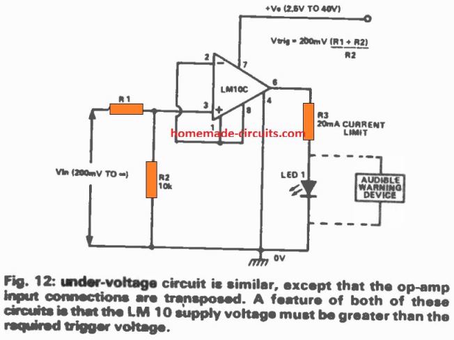
Fig 13 below exhibits a highly accurate under voltage indicator using LED or audible alert. Input sensitivity 50k /v.
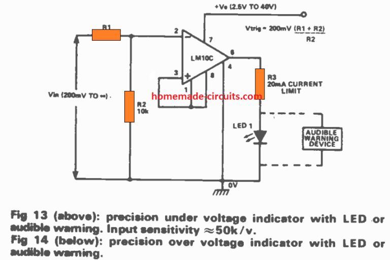
Fig 14 (below): precision LM10 based over voltage indicator using LED or audible alarm unit, The LED will begin indicating if an over voltage situation is present in response to a current trigger at R1/R2 junction.
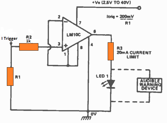
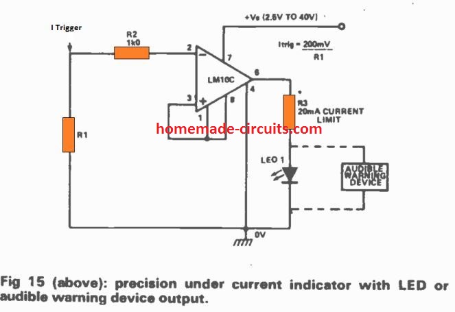
An accurate low current indicator circuit using op amp LM10 is shown in the following Fig 15 which illuminates an LED or buzzer alert unit whenever the current through R1 drops below a set threshold level.
Universal Heat/Light Sensor Amplifier: Figure 16 exhibits a high precision circuit which can be activated through an external parameter, for example through light or temperature sensors. These sensors should have a resistive characteristic like LDR or thermistor.
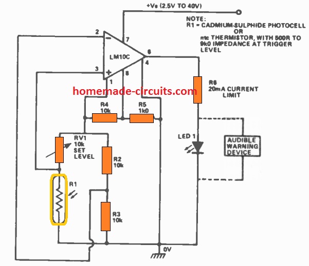
In these designs, the resistive component becomes section of a Wheatstone bridge which is driven through the LM10's voltage reference amplifier, and the bridge output is applied to switch on the op amp rigged as a comparator. In the illustrations demonstrated, the bridge is powered through a 2V2 supply.
Remote Sensor Modules using LM10
The op amp LM10 can be also effectively used as a precision remote sensing circuit module, that can work like temperature, light, voltage detectors at a remote place far away from the actual measuring device. The remote signals is transferred through appropriately shielded cables.
High Temperature Remote Sensor
The next figure shows how an LM10 IC could be configured to detect high temperatures in the order of 500 to 800 degrees Celsius. The circuit could be thus also be employed as a remote fire hazard detector module

*The maximum 800 degrees high temperature detection threshold is achieved by connecting the "balance" pin of the IC with the "reference" pin.
Remote Vibration Detector: The next diagram shows how the IC LM10 could be used for making remote vibration sensor module. The sensor could be a piezo based transducer or similar.
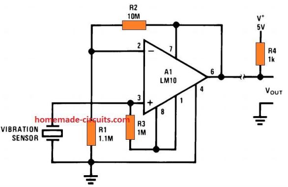
Remote Bridge Amplifier Sensor
The following diagram shows am LM10 wired a remote resistive bridge amplifier sensor.
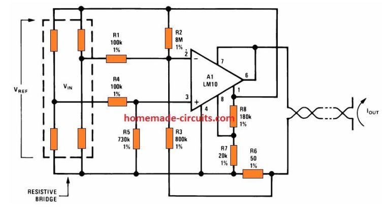
In the resistive any one of the resistors could be replaced with a sensor such as an LDR, photo diode, thermistor, piezo transducer, to create a relevant sensor amplifier. for detecting a over threshold or lower threshold for the detected parameter.
Thermocouple Sensor Amplifier
A thermocouple is a device consists of two dissimilar metals rods or wires joined by twisting at their ends terminals.
Now, when one of the terminals is held at much higher temperature than the other end, current starts flowing through the conductor due to the difference in the temperature at the ends of the dissimilar metals.
In a thermocouple network as explained above, one of the end becomes the reference point, while the other end becomes the sensing point.
However, the current developed in a thermocouple can be extremely small in the order of micro amps.
The following circuit using LM10 op amp can be used to amplify the low current from a thermocouple to measurable levels.
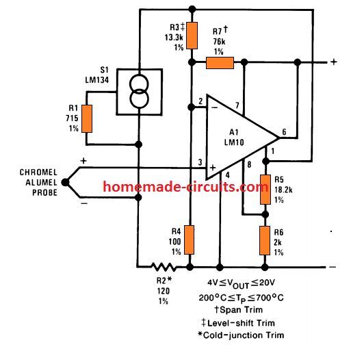
Here, the LM134 generates a precise reference across one end of the thermocouple element, so that an accurate differential temperature can be detected from the other end of the thermocouple, by the op amp.
Miscellaneous Circuits using Op amp LM10
Battery Level Indicator: The battery voltage monitor circuit shown below uses a single LM10 IC to indicate the battery level when it drops below a certain specified limit. Here, the LED remains illuminated brightly as long as the voltage is above 7V and shuts off when it drops below 6V.
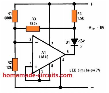
Precision Thermometer Circuit
The next designs shows a precision thermometer circuit using a single LM10 IC.
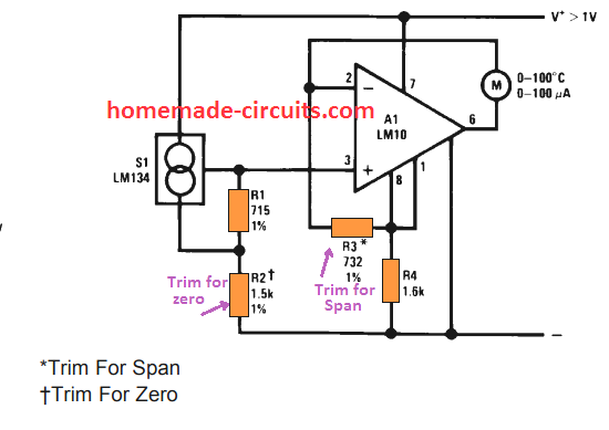
The LM134 in the circuit works like a temperature sensor, which converts the temperature into proportionate amount of voltage.
It converts every degree change in temperature into 10 mV. This conversion is directed displayed over a 0-100uA micro-ammeter through the IC LM10 which is configured as a voltage follower/amplifier.
If you have any queries or doubts regarding any of the above explained LM10 op amp application circuits, you may feel free to contact me through comments below.
Meter Amplifier Circuit
LM10 can be also efficiently used for amplifying millivolts and displaying the reading over an appropriate moving coil meter.
The circuit below is one such circuit in which input voltages from 1 mV to 100 mV is amplified 100 times and produced over an milliamp meter, suitably calibrated to read milivolts.
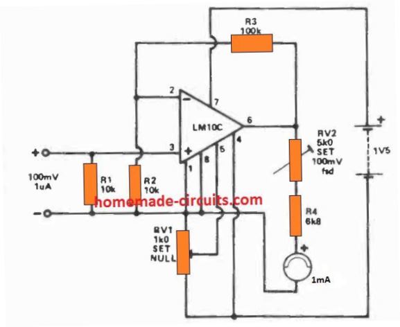
The design also includes a zero adjust facility which allows the user to adjust the meter needle to exact zero so that the final reading is accurate and error free.
The biggest advantage of this circuit is that it works with a single AAA 1.5 V cell.
The above LM10 based meter amplifier circuit could be further enhanced into a 4 range adjustable millivolt meter amplifier circuit as shown in the following diagram.

Reference: LM10
Well and good uses of this ic , very good circuits you are given thankyou sir.
Thank you Maddu!
Thank you for solving the issue, I will try.
250V version of the regulator with output short circuit protection
Hello, I’m looking for advice on improving this scheme. Is it possible to get a slowly rising voltage from 0-250V in this circuit. A little confused by the power of resistor R5
R5 will get quite hot, that is why it is rated at 10 watts. You can try adding a 10uF/250V capacitor between the base of Q3 and the GND line for getting the slow start facility
Thanks for posting this article. very handy
Thanks, Glad you found it useful!