In this post I have explained a simple ambient light dependent LED illumination controller circuit. The light fades or intensifies proportionately i response to the ambient light conditions. With brighter daylights, the LEd illumination gets softer and vice versa. The idea was requested by one of the dedicated members of this blog.
Technical Specifications
While seeking through the internet for a fully automated day/night LED Time Controller, I found your blog and I was wondering if you could help me with an advice. I want to add some kind of controller to give me smooth transition from sunrise/sunset of an aquarium LED lamp and with what I found on internet so far, seems way too complicated or just expensive for my goal.I was looking for something simple, without the need of simulating a thunderstorm through an Arduino board with n channels I will never use. I want something that could light up some LEDs at a given time while fading other LEDs, all with a smooth transition. And this has to repeat twice a day, every day.What do you say, can you help me?The lamp I have, is:12 x Cree XP-G2 R5 - 6500 - 7000K4 x Cree XP-G2 R2 - 2700 - 3200K2 x OSRAM SSL80 Hyper Red- for night time2x CREE XP-G R2All connected through 5 x KSQ 400mA (with the maximum of 6 LEDs in a row for each KSQ 400mA) to a laptop power adapter.Now, I don't know if my LEDs have dimming capability or I have to pass them through some dimmable drivers to obtain the desired effect.Also, the systems I found so far, are all based on a Arduino and they seem bulky. ex. Neptune (Apex), Profilux, Reef Keeper, DIM4So, that being said, thank you in advance for any help.
The Design
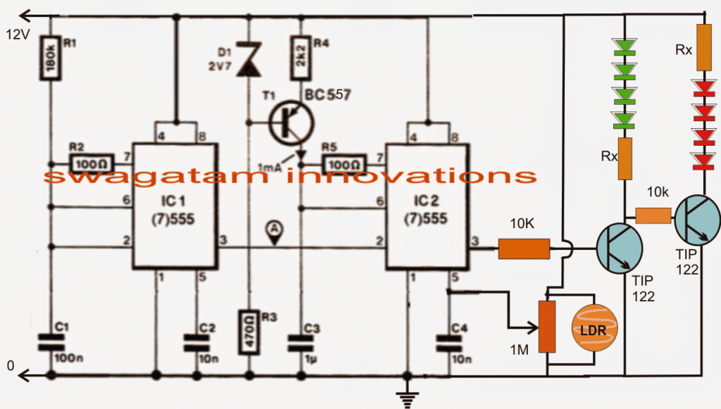
The shown light dependent led controller circuit is basically a light dependent PWM optimizer circuit whose duty cycle varies in accordance with the potential difference or level at its cotrol pinout.
As can be seen the circuit includes a couple 555 ICs. IC1 is configured as a standard astable having a frequency of around 80Hz. This frequency is not crucial in terms of the circuit functioning.
IC2 is configured as a PWM generator such that it compares the square wave signal at its pin2 and the triangle wave across its pin6/7.
This results in an output with a particular PWM content at pin#3 of ICs.
However this PWM duty cycle can be varied simply varying the potential difference at pin#5 of IC2.
An LDR can be seen attached across a potential divider preset at pin#5 of this IC. The preset can be used for fine tuning the results as desired.
The LDR resistance level now determines and varies the potential across this sensing pinout which in turn results in a proportionately varying duty cycle at pin#3.
The varying duty cycle causes the connected transistors to conduct accordingly and produce the correspondingly varying intensities over the connected LEDs.
The two transistors are configured as inverters which ensure opposite responses over the LED sets connected across the collector of the respective transistors.


Questions & Answers
Hello Mr. Swagatam, I love this idea and thank you for creating it. I would like to run this off a 35.5v power supply to run 63 leds, with a total draw of 126.65ma. I already figured the led arrangements and resistors and tested them with the supply, and it all works well. The led string voltages range between 20.5 and 35.2. I know the 555 can’t handle the 35v, can I just use a lm7812 or a lm317 to regulate the power to the 555 and have the collector/leds run off the 35.5v? Also can I use bc547’s instead of the Tip 122’s? As they are not drawing that much. I have tested with the 12volt supply with a few leds and got it working, but the leds connected to the first transistor don’t go out all the way. When I tested it using 1k resistors, they are drawing 3.92ma when on and .17ma when they are supposed to be off. I’m not sure why. I only have a 250k pot, could that be the problem? Thank you for your help.
Hello Jon, the set up which you have mentioned will work, but there are a few things which cannot be implemented as per your specifications:
1) BC547 cannot be used, instead you can try 2N2222 or 8050 transistor.
2) the pin#5 set up as shown may not be too efficient for the operations, therefore we may have to use a transistor stage here to increase the efficiency of the LDR, for this you may use a BC547 with its emitter connected with pin#5 of the IC2, base connected to the positive line through the LDR, and a 100K resistor connected between its base and the ground line. A 4k7 pot may be connected across pin#5 of IC2 and ground for controlling the sensitivity rate of the circuit.
To ensure complete shut off of the LEDs, you may connect a small value resistors across base emitter of the two driver transistors.
Thnx sir i'll buy it
Sir is there any transformerless circuit for charging 12v7ah battery.
you can buy a readymade 14V/1amp smps adapter for charging it.
Thnx sir i'll buy a new one.
Sir i'm about to use it in battery charger but in that circuit transfrmer which does nt hve centre is used…but i hve a centre tapped transformer. Do i need to buy a new transformer without centre tapped or can i use this centre tap one. Sorry sir if my Q is smewhat crazy i'm new in electronics.
sorry I confused it to be the inverter transformer, for the battery charging you can use any transformer that is able to produce 14V after rectification, a 0-12V transformer will work, or 6-0-6 without center tap will also work
Thnx sir. Can i use centre tap transformer without using the centre.
where will you connect the battery positive if the center tap is not used?
Sir i have ac adapter which output voltage is 9v 500ma DC. Can i use this for charging 12volt
the transformer ampere rating should be not less tan 1/10th of the battery AH rating, only then it will charge the battery optimally.
Thnk you sir Swagatam you help me a lot.
Sir swagatam i hve another Q. In the circuit i hve shown you about the charger, it is recomended of using 100uf35v capacitor. But i have 100uf25v and another 100uf65v. Can i choose any one of them or shall i used the recommended one.
And sir for that inverter project i hve bought a 12v5amp transformer and two 2N3005 transistor. But i could not find any 10 watt resistor. I have search many shops but i could not. Is there any replacement of those resistor possible in that circuit. Can i used ten wirewound 1watt resistor in series to get 10 watt. Sorry for disturbing you a lot sir.
Nitu, you can use 100uF/25V since it's a 14V application.
series will not increase wattage, you will have to connect them in parallel
you can use 10nos 1k/1watt in parallel for getting 100ohms 10 watt and 10nos 150 ohms/ 1watt in parallel for getting 15 ohms 10 watt
Thnk you very much sir for ur kind responds.
Thnx sir…pliz give me a simple and low cost battery charger for using in this project.
you can use the linked circuit that you had referred to. 2amp trafo will work, you can use 1N5402 diodes in it.
One more qstn sir…here in the part list 32ah battry is given. Can i use any other bttery of lesser ah?
yes can be used, but smaller battery will give shorter backup time.
Thnx sir
Thnx sir i hve seen the circuit but i have a confusion. In that circuit R1 and R2, can i choose 100 ohms and 15 ohms resister instead of that wirewound. I'm new in electronic so help me pliz sir.
Ordinary carbon resistors will burn quickly, you will have to use wirewound type resistors only, an example can be seen in the following image:
ecx.images-amazon.com/images/I/31xsAi4M7rL._SY300_.jpg
Sir i'm nitu. Pliz give me a circuit for inverter for lighting five 15watt cfl bulb.
Nitu, you can try this circuit:
https://www.homemade-circuits.com/2012/02/how-to-make-simplest-inverter-circuit.html
Please sir, i bought a small transformer of 9V 500mA(I want to use it as a stepdown transformer). I want to convert its secondary coil's voltage and current to 6V ,3A respectively. My question is, what should be the length of the wire in centimeter(cm) and its thickness in millimeter(mm). If possible, show me how to calculate for its voltage and current without considering the number of turns and the primary coil
sorry, it's very difficult, I have no idea about it.