In the previous article I explained about ripple factor in power supply circuits, here we continue and evaluate the formula for calculating ripple current, and consequently the filter capacitor value for eliminating the ripple content in the DC output.
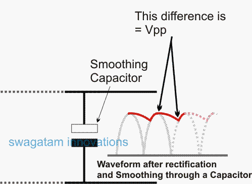
The previous post explained how a DC content after rectification may carry the maximum possible amount of ripple voltage, and how it may be reduced significantly by using a smoothing capacitor.
Although the final ripple content which is the difference between the peak value and the minimum value of the smoothed DC, never seem to eliminate completely, and directly relies on the load current.
In other words if the load is relatively higher, the capacitor begins losing its ability to compensate or correct the ripple factor.
Standard Formula for Calculating Filter Capacitor
In the following section we will try to evaluate the formula for calculating filter capacitor in power supply circuits for ensuring minimum ripple at the output (depending on the connected load current spec).
C = I / (2 x f x Vpp)
where I = load current
f = input frequency of AC
Vpp = the minimum ripple (the peak to peak voltage after smoothing) that may be allowable or OK for the user, because practically it's never feasible to make this zero, as that would demand an unworkable, non-viable monstrous capacitor value, probably not feasible for anybody to implement.
Let's try to understand the relation between load current, ripple and the optimal capacitor value from the following evaluation.
Relation Between Load Current, Ripple, and Capacitor Value
In the mentioned formula we can see that the ripple and the capacitance are inversely proportional, meaning if the ripple needs to be minimum, the capacitor value needs to increase and vice versa.
Suppose we agree to a Vpp value that's, say 1V, to be present in the final DC content after smoothing, then the capacitor value may be calculated as shown below:
Example:
C = I / 2 x f x Vpp (assuming f = 100Hz and load current requirement as 2amp))
Vpp should be ideally always a one because expecting lower values can demand huge unpracticable capacitors values, so "1" Vpp can be taken as a reasonable value.
Solving the above Formula we get:
C = I / (2 x f x Vpp)
= 2 / (2 x 100 x 1) = 2 / 200
= 0.01 Farads or 10,000uF (1Farad = 1000000 uF)
Thus, the above formula clearly shows how the required filter capacitor may be calculated with respect to the load current and the minimum allowable ripple current in the DC component.
By referring to the above solved example, one may try varying the load current, and/or the allowable ripple current and easily evaluate the filter capacitor value accordingly for ensuring an optimal or the intended smoothing of the rectified DC in a given power supply circuit.


Questions & Answers
Great site, Swagatam!!
Hope it gets better and better 🙂
My question is about an old chinese computer SMPS. All the output voltages are low. These smps use minimum filter capacitor values, so what would be the correct values for the 12v and 5v rails on a 500w smps.
If I triple the existing output capacitor values would there be any adverse effect on the computer?
Thank you Bruce, Glad you liked this site!
In SMPSs the output filter capacitor is smaller because of the very high frequencies used in SMPS circuits.
As the frequency increases the capacitor value decreases.
However, increasing the capacitor will only help to produce cleaner and smoother DC outputs, so increasing the capacitor value will only enhance the DC quality and have no adverse effects on the load.
Thank you for your prompt reply Swagatam!
I hope your site becomes one of the leading sites for electronics hobbyists/inventors/kit builders. 😉
Thank you so much for your kind words, I appreciate it very much.
sir, namaskaar hamein vpp apne load ke hisaab se kitna rakhna chahiye ya phir vpp hamesha har circuit mein 1 hi rahega.kripya bataye
Ashu, Vpp can be always assumed to be 1 which is an acceptable value for all types of filter capacitor calculations.
Lets look at a circuit that has 42Vp from a fwbr. Output current is up to 130Adc into a capacitive load Z=.000503j ohms(~5F @120Hz). Capacitive load does not charge up as it creates a continuous arc. Im coming up with a 28000uF 63V cap for filter. You agree?
If you have calculated the result using the formula and the parameters provided in the above article, then it should be correct.
Hi.
In your worked example, you write “C = I / 2 x f x Vpp” which is, of course, incorrect. The correct formula is the one you write correctly before it:
C=I/(2 x f x Vpp) where I = current (amps), f = frequency (Hertz) and Vpp is the Peak to Trough voltage difference (volts).
Although I note that you say 1 volt is a useful ripple current. I build guitar effects pedals where 1 mV is the desirable ripple current (a guitar signal ranges from less than 1 mV to 1V).
In my guitar amplifier, with a Vsupply of 400V, a Vpp of 20V after the primary filtering capacitor is acceptable. Further filtering (Resistor-Capacitor type) is used to reduce Vpp at the amplifier. As you’re aware, two smaller capacitors, separated by some resistance is more effective than a single capacitor. (e.g. in the example of the amplifier above, a 47uF capacitor is inferior to a 10uF capacitor followed by a 1kohm resistor and another 10uF capacitor (for a load of 100kohm)).
cheers
Dear Sir,
Please sir, does the formula also apply for battery power supply?
For instance, 12V 12Ah lead acid battery, what’s the capacitance value to be used?
Hi Godfrey, Filter capacitor is never required for battery power supply, because battery DC does not have any ripple voltage
Calculate the C-filter capacitance which will lead to a 3.5% ripple when the load is 112 mA while the input to the filter is 21Vpeak? Show your solution.
Can you help me how to solve this
Looks difficult to me since the ripple is in percentage and a load current is involved…all these will require different sets of formulas to solve.
Hi, thank you for the very clear and useful information. I assume that 1 volt of ripple means that the peak v drops down by 1v. Example: if I am supplying the load with 120v then the ripple will be 120 peak down to 119 and up to 120 etc. Is this correct?
Also, the use of anode and cathode are confusing. I looked it up online and one thing said cathode is the negative terminal and another said it is the positive. Because of the danger of connecting an electrolytic capacitor backward, can you tell me with just positive or negative. Example: my bridge diode is marked with a + and – and the electrolytic capacitor also has + and – I understand that I connect the capacitor in parallel between the diode and the load (a dc motor) So, do I connect the + terminal of the capacitor to the wire connected to the + terminal of the diode? or to the negative?
Hi, thanks, regarding the ripple voltage your understanding is correct.
Cathode, anode terms are used for diodes and LEDs…anode refers to the terminal which accepts the positive voltage…and cathode refers to the terminal which is connected towards the negative of the supply. For electrolytic capacitors we always use the term negative/positive.
Yes the + terminal of your capacitor will go to the + supply line.
Sir,
I am designing a current source inverter where a capacitor is introduced in the input DC side. This capacitor has to provide the 100hz ripple that is present at the output. What would be the design if this capacitor??
Hello Jennifer, I have not yet investigated the current source inverter in details, therefore I am not well versed with this concept so far!
Hello Swagatam
Do you work in the world of vacuum tubes(circuits)?
Thank You
Larry
Weastminster Colorado
Hello Larry,
Sorry, I do not have any ideas regarding how vaccum tubes work.
Hello, I was going to edit my previous comment/post but looks like it is not possible. So this a follow up.
When I used your formula the capacitance I need is 160,000 uf. That is a lot. I have never seen an electrolyte capacitor with such rating. The most, the highest rating electrolyte capacitor I have seen is 4500 uf and something like 220volts.
If that is what is needed, that is a lot of capacitors.
The calculation will provide the most ideal value, which is actually not required in real life experiments, since slight bit of ripple is always acceptable.
4500uF/220V is a huge value and should be enough to completely stop the humming sound.
I had that electrolyte capacitor wrong in terms of polarity. It is a good thing it did’t explode. Today I installed one correctly 470uf, 200V. I noticed it didn’t make much difference. Someone on youtube was saying that the ferrite thing he used with wires looped in it between the rectifier and the motor helped a lot more than using capacitor. I am thinking of using that ferrite along with a choke, if that makes any difference. Also the AC voltage regulator has 500K potentiameter. I am thinking of installing a 100K, because I have to turn the potentiameter more than half way for the motor to even turn and the capacitor made it even worse and had to turn the knob even more.
Thanks for updating the info…you can definitely try those modifications, hope it solves the problem!
Hello Sir,
I am trying to get DC power supply to run a Treadmill motor. It is 3HP, 100V 23 A motor.
I am using an SCR AC power supply and got a full bridge rectifier. The motor runs. But there is that hum. I can not for the life of me can understand what rating of smoothig capacitor I should use to soften the hum. I assume I need to use an electrolyte capacitor.
Even after reading your article I still don’t get what voltage and what capacitance I need. Also I don’t mind using multiple capacitor and or combined with resistor or whatever it takes to do it right. I have plenty capacitors and resistors or what have you. I appreciate any help you can throw my away. And thank you for everything you do.
Hello Ali, voltage of a capacitor indicates the maximum voltage that it can handle, and exceeding that voltage will cause the capacitor to burst….it has nothing to do with the microfarad value of the capacitor or the smoothing level of the capacitor. If your supply is 100V then the voltage of the capacitor can be 150V to be perfectly safe.
If your 100V DC is coming from a bridge rectifier then you can connect the smoothing capacitor directly across the +/- supply lines, no resistors will be required.
You can try 500uF/150V or 1000uF/150V and this will stop the humming sound for sure. The capacitor can be electrolytic or non-electrolytic it does not matter.
Calculating the capacitor is not required, you can randomly go on increasing the value until you find the humming sound completely gone.
I should have mentioned that I used a 1000uf, 200V electrolyte cap, + to the arrowhead side of the rectifier, parallel to the motor and rectifier and in between them, it got hot pretty good. In fact it tripped the breaker on the recepticle. I assume that is how it is wired, its’ positive to the arrow head side of the full bridge rectifier and negative on its tail end. Unless I had it wrong. Someone said if I had it backwards it won’t work… whatever was meant by that.
Should I use a capacitor from Microwave oven, 1 MF and 1000V?
Thanks in advance.
Yes the capacitor must be connected across the bridge rectifier output, with the positive of the capacitor going to the cathodes of the bridge diode.
1 Farad is huge and should be enough to cancel the ripple voltage effectively.
That is 1Farad on the microwave cap oven, not 1MF. 🙂
how would you go about solving this problem?
A 60 V peak full-wave rectified voltage is applied to a capacitor-input filter. If f = 49 Hz, R = 9 kΩ, and C = 44 μF, the ripple voltage is ………
Hello, I have a BLDC motor controller rated for 22.2V and 50A, I need to put the input power filter capacitors on them. how should I proceed? Motor operating voltage is 22 volts, peak current draw is 40A.
You can use 3 capacitors, join their each end in common, and connect the other 3 ends of the capacitors with the 3 wires of the BLDC motor.
I am trying to build a 250 to 300 volt 5 to 6 amp power supply or battery charger to charge the battery on my 03 Prius thanks if you can help
You can build the auto cut off circuit by referring to the following circuit:
https://www.homemade-circuits.com/high-voltage-360v-battery-charger/
I do not understand. So you should have a capacitor of 20000uf in the example above?
C = I / 2 x f x Vpp
= 2 / 2 x 100 x 1
= 0.01 Farads or 10,000uF (1Farad = 1000000 uF)
Where did you get the decimal point from?
I’m trying to figure out the size of capacitor for a kbpc3508 diode bridge rectifier.
C = I / (2 x f x Vpp)
= 2 / (2 x 100 x 1)
= 2 / 200
= 0.01 Farads
0.01 Farads is 10000uF and not 10,000uF or i am wrong here?
In English the “,” is used between “thousands”. “.” is the decimal point.
So your two values are the same thing.
sir, your circuit is great but i have questions to you …how did you do ?
very good post and site
and about calculating filter capacitor voltage what’s your idea?
Thank you Jack!
Thank you so much for your clarification. You have helped so much.
You are welcome!!
A very good post that I have learnt a lot. Please how do we measure/calculate/obtain the Vpp?
I am glad you liked!!
Vpp is the final ripple that may appear with the DC after rectification, and it is supposed to be zero ideally, but in the practical world a zero ripple cannot be possible, and moreover that would demand a huge filter capacitor…therefore we assume this value to be around “1” for all filter capacitor calculations
Sir output of my transformer after rectification is 11.9v I want to charge my 12v battery please suggett the capacitor rating I want to use here to charge my battery please reply fast
Vijay, if you are interested t calculate the exact value of the capacitor then you'll need to evaluate charging current first, which can be found by dividing the AH of your battery with 10.
In general you can simply use the highest value capacitor that may be feasible for you.