This IC 555 software calculates the values of the resistors and capacitors for a NE555 timer chip, which is designed as a astable multivibrator (oscillator), or square wave generator. You simply have to type in the duty cycle and the frequency and the calculator will work out realistic values for the resistors and capacitors.
Alternatively, you can insert the RA, RB and C values manually to check what corresponding output results you get for the frequency and the Duty cycle, and then you can change the figures accordingly until the intended results are determined.
Please remember that the lowest duty cycle will be 50 %, therefore should you need a smaller duty cycle you will need to apply an inverter on the output, by ticking the check box.
Furthermore the parameters explained in the equations of the IC 555 astable timer are only estimations which can be inaccurate by approximately 20% from the empirical outcomes.
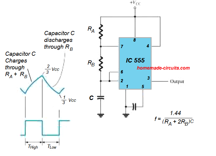
NE555 Astable Circuit Schematic with Calculations
IC 555 Astable Calculator
In a 555 astable circuit, R1 is connected between pin 7 (discharge) and VCC, while R2 is between pin 7 and pin 6. The capacitor (C) is connected between pin 6 and ground.
Results:
Frequency: 0 Hz
Duty Cycle: 0 %
ON Time: 0 ms
OFF Time: 0 ms
Questions & Answers
Sir may be I not explained proper.i m saying relay has three point {com ,No,Nc} Timer is set 5sec when I give the supply in timer. The timer relay not ON after 5sec timer relay ON and never stop when I cut supply than relay stop and again timer supply on relay on after 5sec. Like on delay timer.
For a delay ON timer you can try the following design:
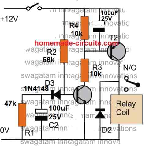
The NPN transistor is BC547, PNP is BC557. You can remove the 100uF, connected across the base of the PNP transistor.
When power is switched ON, the relay will be OFF….after some delay the relay will be ON and will remain ON until power is switched OFF. Now if power is switched OFF and turned ON again, the delay action will be repeated.
Sir I want to 0 to 30 second adjustable timer when supply on relay on.what chang in your circuit.
Pawan, you can build the 1st circuit from the following article. You can replace 470K with a 470 K pot, and make sure to put a 10K resistor in series with this 470 K pot.
https://www.homemade-circuits.com/interesting-timer-circuits-using-ic-555-explored/
Sir in this circuit pin no 2 has push button I want without push button can I connect pin no 2 direct ― supply and sir I want to star delta timer 0 to 60 sec can I go with ic 4060 because you tell this is accurate and industrial.my application is when motor start first star contact on after selected time star off and delta contact on means when supply on relay on after selected time relay off nager again on when supply off and again on timer relay on
Pawan, start/stop contactor function for motors cannot be achieved using a simple 555 IC. You will need two separate 555 monostables with relays whose inputs will need to controlled with another timer IC such as 4060.
Examples of the start stop for a water level pump is discussed in the following article:
https://www.homemade-circuits.com/borewell-motor-pump-starter-controller/
Hello Sir, I want to make a loop timer of 20 minutes to turn on & off 2 bulbs (AC 220V 400W each) one by one, so what i thought of is make a timer that turns on a relay for 20 mins then turn off the relay for 20 mins then turn back on the relay for 20 mins and so on till the power is on. I planned to use relay’s NO & NC function to connect both bulb A & B so that when the relay turns on, bulb A connected to the NO will turn on & bulb B connected to the NC will turn off, similarly when the relay turns off, bulb A connected to the NO will turn off & bulb B connected to the NC will turn on.
I have no idea how to put fq. in above calculator, i guess the duty cycle gonna be 50% since i wanted the relay to keep on & off with a 20 mins time gap.
so kindly please tell me the exact value of the C1, R1 & R2 respectively.
I was thinking about a 1mega ohm variable resister to be use in place of R2 for changing the time cycle of the timer.
also was planning to use a 6-0-6 500ma transformer to power the above tmer with the 12v using the two 6v lines of the transformer.
Waiting for your Positive Reply,
Thanks a lot in Advance.
Hello Amit, A 555 astable might not give proper results, instead you might have to use a 4060 IC based astable, as explained in the following article. You can try the second schematic. Use 2uF/25V non polar for C1, 2M2 for R1, 1M pot for P1, and 470K for R2. You may have to adjust P1 through some trial and error to achieve the required time interval. Please refer to the comment with “johnny” to understand an easy way to set the desired time interval. The timer output can be achieved from pin#3 of the IC.
https://www.homemade-circuits.com/how-to-understand-ic-4060-pin-outs/
I am not understanding where the frequency, F appears on the NE555 chip. Is it within the chip or at the terminal 3. you can also explain who the switching frequency on the mosfet is achieve to finally have a 220V, 50Hz output on a grid tie solar inverter.
It is at pin 3 of the IC. For a 555 inverter you can refer to the following post
6 Best IC 555 Inverter Circuits Explored
I am looking at making a circuit that will be off for 30 seconds then on for 10 minutes when power is applied to the circuit
hello sir
iam sorry for language
but i need timer used for home
off about 20 minute and on about 1 minute and repeat it
Hello Rami, you can probably try the first circuit from this article:
https://www.homemade-circuits.com/how-to-make-simple-programmable-timer/
I need a 555 Pulse Generator Circuit with independent dynamics in both frequency and duty cycle i.e as I adjust the potentiometer one, it must not affect the other. Also the duty cycle should be from 0% to 100%.
Could you please help me with one?
You can use the second circuit from this article:
https://www.homemade-circuits.com/pwm-motor-soft-start-circuit/
the two pots will provide the PWM ans freq control separately
Swag sir…
How i find the 1000uF capacitor with 25V ?
I want to make a low high cut out circuit using relays for 12 v0lt car battery using IC or Transistor
you can use the following concept, remove the transformer and wire the relay with the desired load
https://www.homemade-circuits.com/simple-mains-ac-over-voltage-and-under/