In this post I have explained how electret microphone devices work, through appropriate diagrams and formulas.
What's a Microphone
A microphone is a device designed for transforming weak sound vibrations into tiny electrical pulses, which can be then amplified through a power amplifier over a loudspeaker for achieving a louder reproduction of the sound.
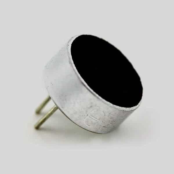
The most common and versatile form of microphone device employed in electronic circuits are the electret microphones.
These MICs are miniature in size, extremely sensitive, and are able to capture or respond to sound vibrations from across all angles, that is from across a full 360 degree angle.
How Electret Microphones Work
- An electret microphone mainly consists of a diaphragm, a couple of electrodes and an in-built JFET.
- The diaphragm is made of thin Teflon material and is also termed as “electret” and hence the name electret MIC.
- This electret has a fixed charge (C ) and is embedded between the two electrodes.
- The electret along with the two electrodes takes the form of a sensitive variable capacitor whose outer surface responds to sound vibrations, giving rise to a varying capacitance across the two electrodes.
- Sound waves in the form of air pressure moves one of the electrodes facing the open side of the MIC, causing effective variations across the capacitive plates .
- The instantaneous value of the varying capacitance of the MIC becomes directly proportional to the sound pressure hitting the electret at that instant.
MIC Capacitance Calculation
As mentioned earlier, since the charge value on the Teflon material is fixed, the potential difference developed across the MIC capacitor becomes equivalent to the value which can be expressed with the following formula:
Q = C.V
Where Q is the charge (which is fixed for the electret)
C indicates the capacitance, while the V signifies the developed voltage level or the potential difference across the electrodes.
The above discussion implies that the electret MIC's internal construction behaves like a AC coupled voltage source.
Most electret MICs have an in-built JFET whose gate is connected with the electret capacitor forming an buffer for the MIC’s capacitor.
Since the charge of the capacitor is fixed, this buffer needs to be of a very high impedance and that’s exactly why a JFET is used.
The following diagram shows the basic internal wiring layout of a typical electret microphone.
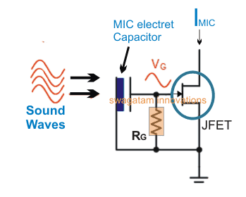
Sound vibrations hitting the electret capacitor varies its capacitance producing a modulating voltage for the gate of the JFET, indicated as Vg.
This modulation alters the current flow pattern across the drain/source of the JFET, represented as Imic.
A stabilizing resistor RG can be also seen connected internally across the gate and source of the JFET, it is ensured that this resistor has an extremely high value to avoid shunting of the electret output for the JFET gate.
Sectional View of an Electret MIC internal Structure
The following image shows a sectional cut view of an example electret MIC.
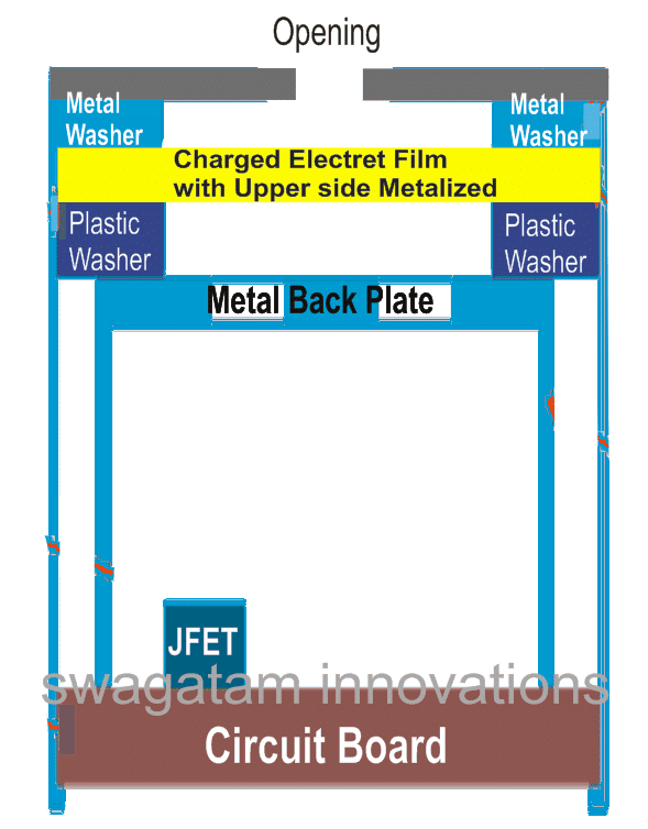
One of the electrodes is formed by metalization of its layer over a charged polymer film.
This metalized layer is joined with the case of the MIC through a metallic washer.
The case of the MIC is in turn connected with the source lead of the internal JFET.
The other capacitor plate or the second electrode is made by using a backside metal plate, which can be seen separated from the metalized layer film by a plastic washer. This plate is then connected with the gate terminal of the JFET
Sound waves hitting this plate generate a strain level on it, thereby varying the distance between the capacitive electrodes, and causing an equivalent potential difference to develop across them.
This varying voltage across the drain of the JFET is used as the output for a subsequent preamplifier circuit stage which further amplifies this to a level which can be reproduced over a loudspeaker, and an amplified version of the sound waves can be heard.
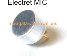
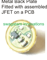
Internal Composition of an Electret MIC
A following images show the actual parts used inside a typical electret MIC


If you have more questions regarding how electret microphones work, please do not hesitate to put them forth through the comments.


Questions & Answers
Hello sir, I am using a electret microphone for a electronics practice in my university, my question is, how I can view the change on the mic before the amplification phase and after of this, thank you
Hello Nicolas,
You can connect an oscilloscope across the MIC terminals and monitor the changes in the momentary waveforms whenever it detects a loud sound.
Is there any specific configuration for the oscilloscope? I tried to see the signal on the oscilloscope, but I was not able to. Also If you can share a beginner’s guide for oscilloscope use, I would appreciate it.
You can build the following circuit, and test the waveforms by connecting scope probes across base/ground of the transistor, and then across the output/ground of the circuit:
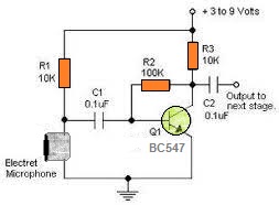
Make sure to keep the oscilloscope at maximum sensitivity.
Thank you so much, Mr. Swagatam.
You are welcome Nicolas…
Hi Swagatam! I would like to create a circuit that uses an electret mic to advance a cd4017. A musical chip would provide the sound to the mic. The music will be related to Christmas and I would like to trigger the mic on the stronger beats. The cd4017 would advance and light a row of Leds on a Christmas tree. Each advance of the cd4017 would light a different row of Leds. Any help would be appreciated. Thanks!
Hi Norman,
You can try the first circuit from the following article. You just have to integrate the collector of T3 with the pin14 of IC4017. Just make sure to use a series resistor and a ground capacitor connected between T3 collector and pin14 of IC 4017:
https://www.homemade-circuits.com/simplest-sound-activated-relay-switch/
https://www.homemade-circuits.com/wireless-music-level-indicator/
What do I do to relocate one of these ( what amp circuit to use and what output signal needs to look like )
Hers’s an example circuit using electret MIC. Output will be an amplified version of the input AC
Thanks
So I can just desolder the mic capsule and adding the circuit with a mic with a cable with a 3.5mm plug
Yes that is possible.
Great article.
Could you please expand on the differences in construction of omnidirectional versus unidirectional microphones?
Thanks,
Terry
Thank you for liking the post. I have not studied the mentioned topics yet, but i’ll try to investigate it and update the info here, soon
Interesting. This really explain much. When read electret microphone capsule datasheets, there is “this is -58 dB model” etc. Looks all electrec microphones are quite similar. Differencies are only dimensions and frequency areas. But look this “decibel value” is most important. What it mean? Eg. if I make any amplifier, how I can use this information, if I want to be exact and design all using “science”?
Thanks, decibel seems almost same in all the eletret mic datasheet, so I am not sure how it can be so crucial. I think the biasing resistor decides the sensitivity level of the MIC which can be tweaked easily.