This page explains how to calculate the pulse duration of a monostable multivibrator using a 555 timer IC. Just put the resistance and capacitance values, and it will show the output pulse width (Tp) in seconds.
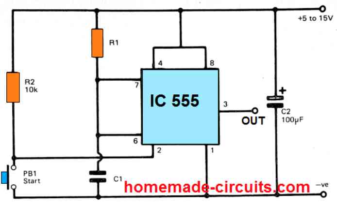
As per a standard IC 555 calculation law, it is advised to select the resistor values higher than 1K and lower than 1 Meg. The Capacitor with high values of electrolytic capacitor should not be used, rather larger value R's must be opted which will ensure lower power consumption and higher accuracy of the output time delays due to lower leakage.
Calculator by homemade-circuits.com
EXAMPLE:
Inputs: Resistance = 220KΩ, Capacitance = 1µF
Output: Pulse Duration = 0.242 seconds (or 242 milliseconds)
Questions & Answers
please my honorable mentor i need a stable timer delay circuit that can delay up to 5minute before it will go off and never come back until i reset it back.thanks
Adeleye, you can try the second circuit from the following article:
https://www.homemade-circuits.com/how-to-make-long-duration-timer-circuit/
Hi mate
kindly I’d ask please for a circuit I’m trying to design depends on square wave . the circuit is about electroplating by the square wave instead of dc voltage. the frequency would be variable between 10-50HZ and the duty cycle 50%. what would the circuit and components would be please?, and in case of 555timer datasheet gives 200mA max current what the extra components i would add to the circuit to make adjustable current rises up to 1A and would that affect the output voltage. Can I put adjustable resistor to the Vcc only and would it drop the output voltage.
I owe you the most thanks
Regards
Hi Kenan, I would recommend a 4060 based design, as given in the second last diagram from this article:
https://www.homemade-circuits.com/how-to-make-simple-versatile-timer/
The LEDs are optional. Use a 2N2222 instead of BC547 for the transistor
IC 555 is not good.
Dear Sir,
i want to design timer circuit 30 minutes with IC555, power supply press the circuit button works 30 minutes then turn off, or active, press the button will turn off, press the button will work. Every 30 minutes, please help me.
Thank you!
Tanaka, you can try the following circuit:
https://www.homemade-circuits.com/monostable-4/
calculate C and R using the above calculator
C3 = 0.01uF
Thanks, Swagatam.
I have followed the instructions and succeeded with both NE555 and CD4060. These two ICs have the disadvantage that the Timer depends on the capacitor, the quality of the capacitor decreases over time. So do you know which IC series has a timer of up to 30 minutes without depending on the capacitor? (excluding IC running by program algorithm)
thanks
Hi Tanaka,
The modern good quality capacitors will last over 10 years without any deterioration. And you also have tantalum capacitors which might last almost forever.
Still if you are not satisfied in that case you must go for an Arduino based timer such as this or any other which may be available on the net
https://www.homemade-circuits.com/lcd-socket-timer-circuit-using-arduino/
Without programming there’s no other alternative.
izvanrednoo!