Although, most of the car electronics have evolved into solid-sate versions, a turn indicator flasher unit is one device which still depend on a relay based design in many of the modern cars.
Disadvantages of Relay Based Flasher
There are a couple major disadvantages of a relay based electromechanical flasher unit:
1) First, these being mechanical in nature, go through rapid wear and tear and therefore tend to get damaged soon.
2) Secondly, the flashing rate from these electromechanical circuits are load, voltage and temperature dependent. Meaning, the flashing speed can get affected if the ambient temperature is high or if the battery voltage drops, or if the load exceeds a specified limit.
This also implies that if the user wants to flash all the 4 lamps together, he may find the flashing speed too fast and too slow.

Advantages of Solid-State Flasher Circuit
The 3 pin electronic solid state flasher circuit explained here is virtually free from all of these drawbacks. The repetition rate or the flashing rate from this design is practically independent of the supply voltage, ambient temperature, or the load (number of lamps connected).
The circuit also features a warning switch which seems to be very reliable and handy during emergency, or road accident situations. The switch bypasses the car switch and allows the lamps to run directly through the flasher, enabling all the 4 lamps to flash together, sending an SOS like signal during a nighttime road mishap.
In addition the specifications of this design conforms with all the current statutory requirements for car turn indicators.
The repetition frequency of 40 to 90 flashes per minute set in this unit is as per the advised range and also the circuit is designed in such a way that the indicators lamps switch ON instantly when the turn indicator switch is powered.
How the Circuit Works
The circuit is essentially an astable multivibrator built using a couple of CMOS NOR gates N1 and N2. N3, N4. Power transistors T1, T2 and T3 acts like a buffer stage for the output of this astable to operate the high wattage indicator lamps.

Whenever the indicator switch is toggled ON C2 discharges swiftly via D1 and the indicator lamps. Pin 13 of N1 turns high and its output becomes low. The gate N3 and N4 outputs consequently become high, switching on T1, T2 and T3 and turning ON the indicator lamps.
The astable is now initiated to switch at around 1 Hz frequency, causing the indicator lamps to blink on and off at the same rate.
When the hazard warning switch, S1, is turned on, the circuit continues to function in just the identical manner except that all 4 indicator lamps now get linked in parallel and they all begin flashing simultaneously.
T3, which is responsible for handling maximum load current, should be installed on over a heatsink.
When a metallic enclosure is employed to accommodate the proposed 3 pin solid-state flasher circuit then T3 could be clamped to the surface of the case with screw/nut and insulation kit.
The current (amps) through the terminals attached to points A and B can be pretty substantial (up to 8 A) therefore thick wires should be used for these cable connections. The positive battery supply terminal should be installed with a 10 A fuse if it is not included originally.
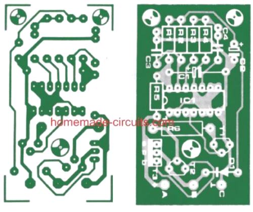
PCB Design
Parts List
Resistors:
R1,R3,R4 = 2M2
R2 = 100 k
R5 = 4k7
R6= 120 Ohm (1 Watt)
Capacitors:
C1 = 1Oµ/16 V
C2 = 1 µ/16 V (tantalum)
C3 = 1 nF
C4 = 220 nF
Semiconductors:
IC1 = 4001 (B)
T1 = BC 557, BC 177
T2 = BC 328, BC 327
T3= FT 2955 or TIP 2955
D1 = 1N4148
Solid-State Car Turn Signal Indicator using IC 4049
A single IC 4049 and a few passive components is all that you need to build the following super easy car 3-pin turn signal indicator circuit.

A single 4049 IC consists of 6 nos of NOT gates.
All these NOT gates are included in the diagram. U1a and U1b NOT gates are configured as oscillator, which generates the flashing rate or the flashing frequency for the indicator bulbs.
The remaining NOT gates are simply used as buffers, to finally power the attached MOSFET.
Since a MOSFET is used, the flasher circuit becomes fully solid-state.
The oscillator frequency activates the buffer, and the frequency is supplied to the MOSFET gate via the buffer stage.
The MOSFET also starts oscillating with the same frequency and powers the indicator lamps ON/OFF.
The switch S1 is the turn signal switch which selects the right or the left flasher bulbs depending on which side the car is turning.
The pot R3 can be used to adjust the flashing rate of the indicator bulbs as per your own preference.


Questions & Answers
Hi, will this work with LED turning lights? Thanks
Hi, you will need to replace the lamps with LED modules
Do I understand correctly that when the base of t1 is drawn LOW, it turns ON the lamps?
‘RileyG’
That is correct!
Then I should be able to use the transistor part of this circuit triggered by an opto isolator that is controlled by the turn signals (object is to not add any more current drain to the turn signals as they stand as they are ‘computer controlled’ and shut off completely if an over current situation is sensed.)
Thank you!
RileyG
Yes, that may be possible!