In this post I have explained the making of simple delay timers using very ordinary components like transistors, capacitors and diodes. All these circuits will produce delay ON or delay OFF time intervals at the output for a predetermined period, from a few seconds to many minutes. All the designs are fully adjustable.
Importance of Delay Timers
In many electronic circuit applications a delay of a few seconds or minutes becomes a crucial requirement for ensuring correct operation of the circuit. Without the specified delay the circuit could malfunction or even get damaged.
Let's analyze the various configurations in details.
You may also want to read about IC 555 based delay timers. Recommended for you!
Using a Single Transistor and Push Button
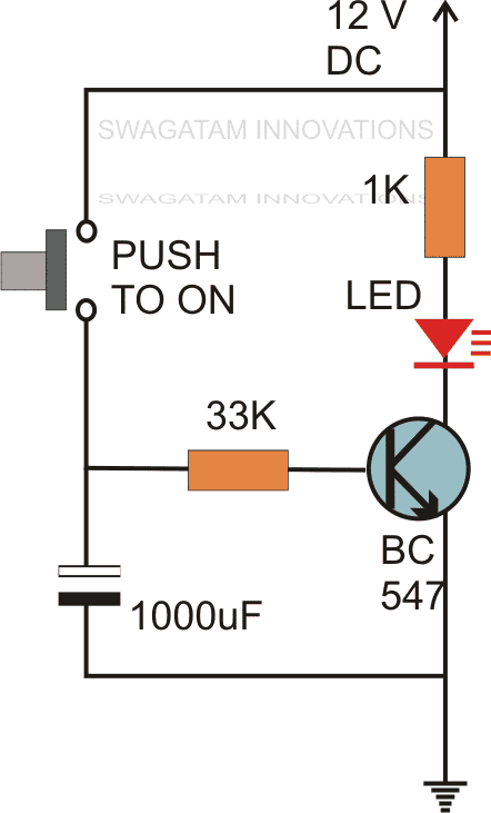
The first circuit diagram shows how a transistors and a few other passive components may be connected for acquiring the intended delay timing outputs.
The transistor has been provided with the usual base resistor for the current limiting functions.
A LED which is used here just indication purposes behaves like the collector load of the circuit.
A capacitor, which is the crucial part of the circuit gets the specific position in the circuit, we can see that it's been placed at the other end of the base resistor and not directly to the base of the transistor.
A push button is used to initiate the circuit.
On depressing the button momentarily, a positive voltage from the supply line enters the base resistor and switches ON the transistor and subsequently the LED.
However in the course of the above action, the capacitor also gets charged fully.
On releasing the push button, though the power to the base gets disconnected, the transistor continues to conduct with the aid of the stored energy in the capacitor which now starts discharging its stored charge via the transistor.
The LED also stays switched ON until the capacitor gets fully discharged.
Te value of the capacitor determines the time delay or for how long the transistor stays in the conducting mode.
Along with the capacitor, the value of the base resistor also plays an important role in determining the timing for which the transistor remains switched ON after the push button is released.
However the circuit using just one transistor will be able to produce time delays which may range only for a few seconds.
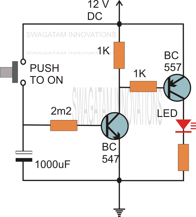
By adding one more transistor stage (next figure) the above time delay range can be increased significantly.
The addition of another transistor stage increases the sensitivity of the circuit, which enables the use of larger values of the timing resistor thereby enhancing the time delay range of the circuit.
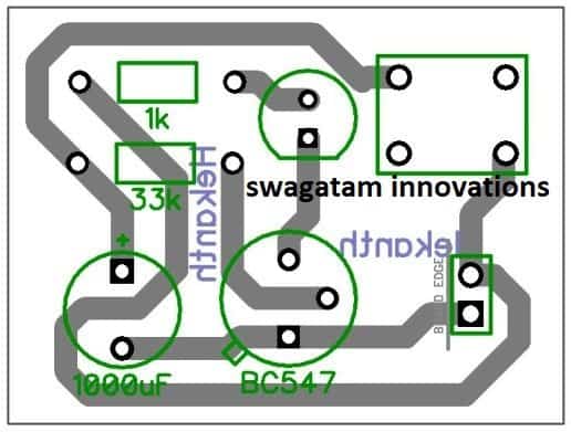
PCB Design
Video Demonstration
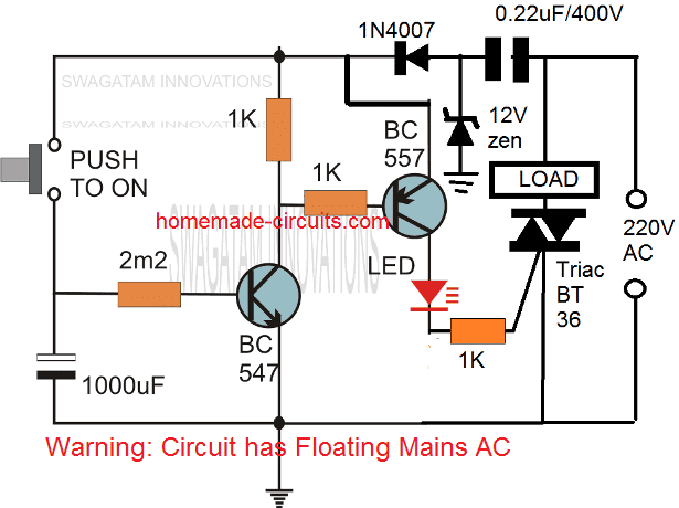
Using a Triac:
The following image shows how the above delay timer circuit may be integrated with a triac and used for toggling a mains AC operated load
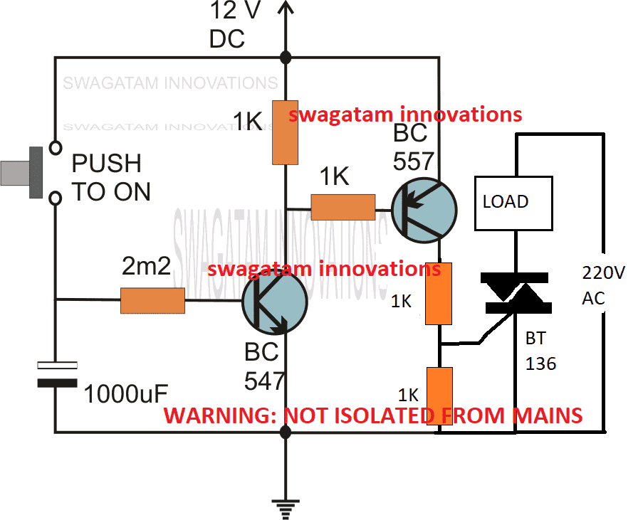
The above could be further modified with a self contained power transformerless power supply as shown below:
Without a Push-Button
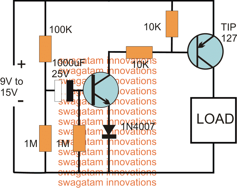
If the above design is intended to be used without a push button, the same may be implemented as indicated in the following diagram:
The above delay OFF effect without a push button can be further improved by using two NPN transistor, and by using the capacitor across base/ground of the left NPN
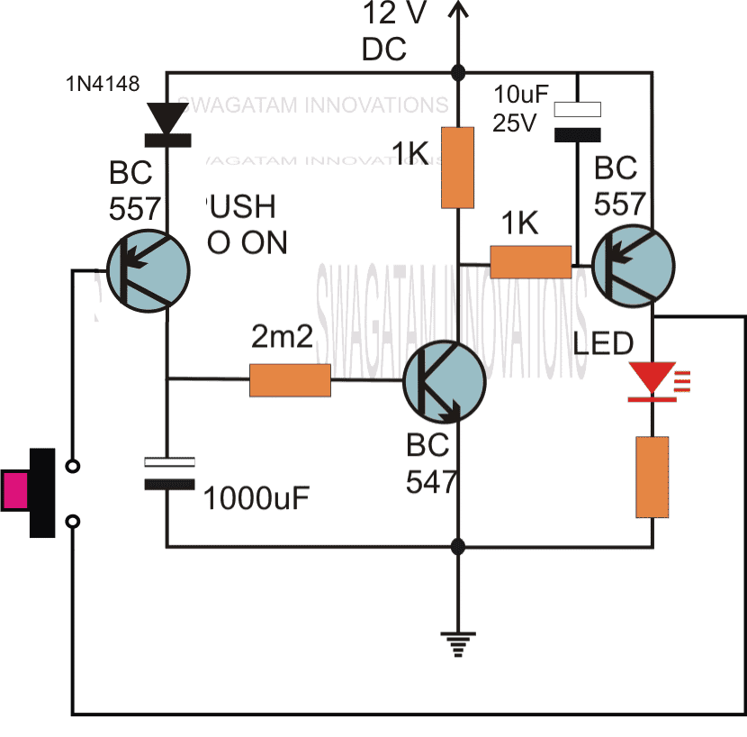
The following circuit shows how the associated push button may be rendered inactive as soon as it's pressed and while the delay timer is in the activated state.
During this time any further pressing of the push button has no impact on the timer as long as the output is active or until the timer has finished its delay operation.
Delay from an External Trigger
Problem asked by Mr. Glen (one of the dedicated readers of this blog):
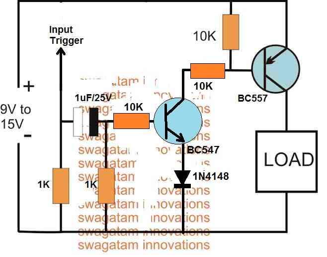
I have a situation where I have a pulse of 12V that lasts about 4 seconds (from a rotary switch being turned by a slow motor) but I only want about half a second pulse (to trigger a mechanical bell/chime).
Is there any way to take a long pulse into a circuit and send a much shorter pulse out?
The solution to the above problem is provided in the following schematic:
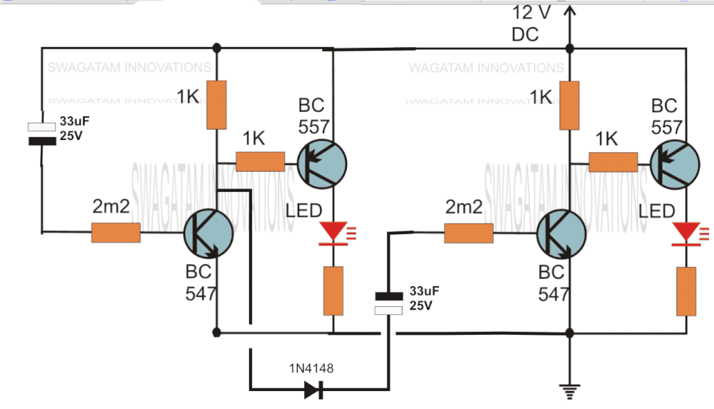
Two Step Sequential Timer
The above circuit can be modified to produce a two step sequential delay generator. This circuit was requested by one of the avid readers of this blog, Mr.Marco.
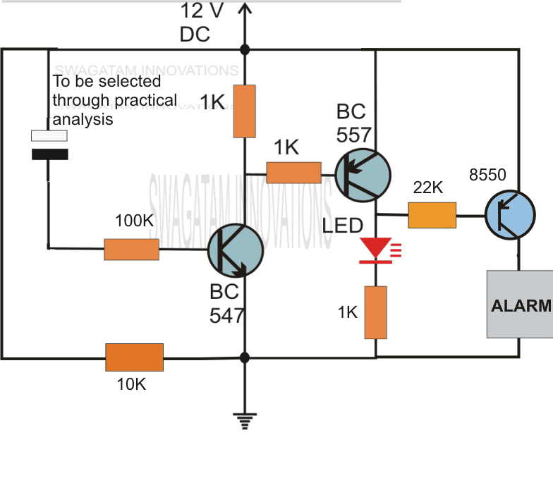
A simple delay OFF alarm circuit is shown in the following diagram.
The circuit was requested by Dmats.
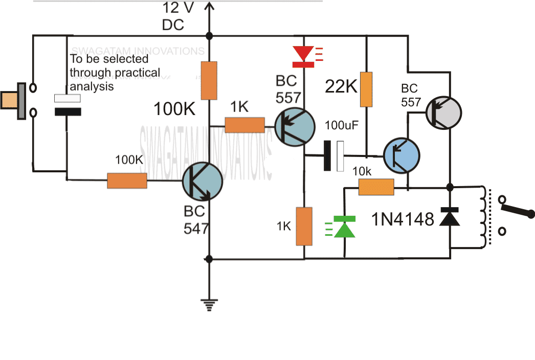
The following circuit was requested by Fastshack3
Delay Timer with Relay
"I am looking to build a circuit that would control an output relay. This would be done in 12V and the sequence will be initiated by a manual switch.
I will need an adjustable time delay (possibly displayed time) after the switch is released, then the output would go on for an adjustable time (also possibly displayed) before shutting off.
The sequence would not restart until the button was pressed and released again.
The time after the button release would be from 250 milliseconds to 5 seconds. The "on" time for the output to turn on the relay would be from 500 milliseconds to 30 seconds. Let me know if you can offer any insight. Thanks!"
So far we have learned how to make simple delay OFF timers now let us see how we can build a simple delay ON timer circuit which allows the connected load at the output to be switched ON with some predetermined delay after power switch ON.
The explained circuit can be used for all applications which calls for an initial delay ON feature for the connected load after the mains power is switched ON.
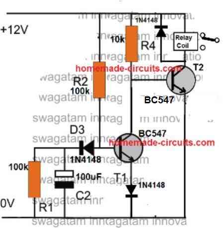
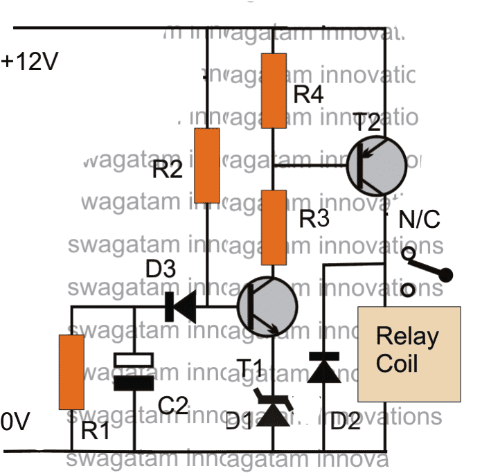
Delay ON Timer Circuit Working Details
The shown diagram is pretty straightforward yet provides the necessary actions very impressively, moreover the delay period is variable making the set up extremely useful for the proposed applications.
The functioning can be understood with the following points:
Assuming the load which requires the delay ON action being connected across the relay contacts, when power is switched ON, the 12V DC passes via R2 but is unable to reach the base of T1 because initially, C2 acts as a short across ground.
The voltage thus passes through R2, gets dropped to relevant limits and starts charging C2.
Once C2 charges up to a level which develops a potential of 0.3 to 0.6V (+ zener voltage) at the base of T1, T1 is instantly switched ON, toggling T2, and the relay subsequently....finally the load gets switched ON too.
The above process induces the required delay for switching ON the load.
The delay period may be set by appropriately selecting the values of R2 and C2.
R1 ensures that C2 quickly discharges through it so that the circuit attains the stand by position as soon as possible.
D3 blocks the charge from reaching the base of T1.
Parts List
R1 = 100K (Resistor for Discharging C2 when circuit is switched OFF))
R2 = 330K (Timing Resistor)
R3= 10K
R4 = 10K
D1 = 3V zener diode (Optional, could be replaced with a wire link)
D2 = 1N4007
D3 = 1N4148
T1 = BC547
T2 = BC557
C2 = 33uF/25V (Timing Capacitor)
Relay = SPDT, 12V/400 Ohms
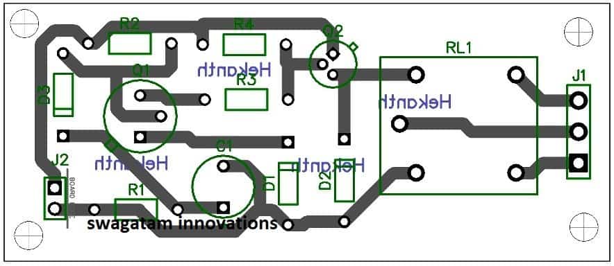
PCB Design
Application Note
I have explained how the above delay ON timer circuit becomes applicable for solving the following presented issue by one of the keen followers of this blog, Mr. Nishant.
Circuit Problem:
Hello Sir,
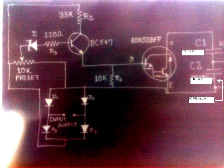
I have a 1KVA automatic voltage stabilizer.It has one defect that when it is switched on, very high voltage is outputted for about 1.5s (therefore cfls and bulb got fused frequently) after that the voltage becomes OK.
I have opened the stabilizer it consist of an auto-transformer,4 24V relay each relay connected to a separate circuit(each consisting of
10K preset,BC547,zener diode,BDX53BFP npn darlington pair transistor IC,220uF/63v capacitor,100uF/40V capacitor ,4 diodes and some resistors).
These circuits are powered by a step down transformer and output of these circuit are taken across corresponding 100uF/40V capacitor and fed to corresponding relay.What to do in order to tackle the problem.please help me.Hand drawn circuit diagram is attached.
Solving the Circuit Problem
The problem in the above circuit might be due to two reasons: one of the relays is switching ON momentarily connecting the wrong contacts with the output, or one of the responsible relays is settling down with the correct voltages a little while after power switch ON.
Since there are more than one relay, tracing out the fault and correcting it can be a bit tedious......the circuit of a delay ON timer explained in the above article could be actually very effective for the discussed purpose.
The connections are rather simple.
Using a 7812 IC, the delay timer can be powered from the existing 24V supply of the stabilizer.
Next, the delay relay N/O contacts may be wired in series with the stabilizer output socket wiring.
The above wiring would instantly take care of the issues as now the output would switch after some time during power witch ONs, allowing enough time for the internal relays to settle down with the correct voltages across their output contacts.
Feedback from Mr. Bill
Hi Swagatam,
I stumbled across your page doing research on the web to make my delay more consistent.Some back ground information first.
I am a bracket drag racer and launch the car on first sight of the 3rd amber bulb as the christmas tree is coming down.
I use a transbrake switch that is depressed to lock the automatic transmission in forward and reverse at the same time.
This allows you to rev up the engine to build power for launch. When the button is released the transmission comes out of reverse and moves the car forward under high rpm.
This is like popping the clutch on a manual transmission car, anyway my car reacts to quickly and the result is a redlight, leaving to early, and you lose the race.
In dragracing your reaction time on the launch is everything and it is a game of hundreths-thousanths with the big boys, so I have put the transbrake switch on a relay and put a 1100uf cap combo across the relay to delay its release.
Because of the car electronics I don't believe there is a precise voltage charging this cap every time I activate this circuit and precision is key so I bought a power stabilizer off of Ebay that takes 8-15 volts in and gives a consistent 12volts out.
This turned my season around but i believe this circuit could be made to be more precise and to vary the delay time in an easier way rather than swap cap combos.
Also should I run a diode in front of the relay, not currently because all that is there is the on off switch- where will the current go? I am not an electrical engineer by any means but do have some knowledge from trouble shooting high end audio for many years.
Would love your thoughts- thankyou
Bill Korecky
Analyzing and Solving the Circuit
Hi Bill,
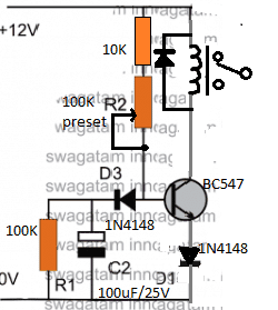
I have attached the schematic of an adjustable delay circuit, please check it out. You can use it for the mentioned purpose.
The 100K preset can used and adjusted for acquiring precise short delay periods as per your specifications.
However, please note that, the supply voltage will need to be minimum 11V, for the 12V relay to operate correctly, if this is not fulfilled then the circuit might malfunction.
Regards.
Simple 5 to 20 Minute Delay Timer
The following section discusses a simple 5 to 20 minute delay timer circuit for a specific industrial application.
The idea was requested by Mr. Jonathan.
Technical Requirements
While trying to figure out a solution to my problem on google, I came across your above posting.
I'm trying to figure out how to build a better Sous Vide controller. The main problem is that my water bath has a very high hysteresis, and when heating from colder temperatures will overshoot about 7 degrees from the temperature at which power is terminated.
It is also very well insulated, with a gap between the inner and outer vessel which makes it act like a thermos jar, because of this it takes a very long time to decline from any excess temperature. My PID controller has an SSR control output and a relay alarm output.
The alarm can be programmed as a below limit alarm with an offset from the set-point. I can use a five volt supply I already have for my circulation motor to run through the alarm relay and drive the same SSR the control output is driving.
To be on the safe side and protect the PID controller I'll add a diode to both the alarm voltage and the control voltage to prevent one output from feeding back into the other.
I'll then set the alarm to stay on until the temperature rises above the set-point minus 7 degrees. This will allow the PID tuning to be adjusted without having to account for the initial temperature ramp-up.
Because I know that last few degrees will be achieved without any power input, I'd really like a way to delay any recognition of the control signal for about five minutes after the alarm shuts off, as it will still be calling for heat.
This is the part I've yet to figure out the circuitry for. I’m thinking of a normally closed relay in series with the control output, which is held open by the alarm signal.
When the alarm signal is terminated, I need a delay on the order of five minutes before the relay returns to its ‘off’ normally closed state.
I would appreciate help with the delayed off portion of the relay circuit. I like the simplicity of the initial designs on the page, but I get the impression they wouldn’t handle anywhere near five minutes.
Thank you,
Jonathan Lundquist
The Circuit Design
The following circuit design of a simple 5 to 20 minute delay timer circuit can be suitably applied for the above specified application.
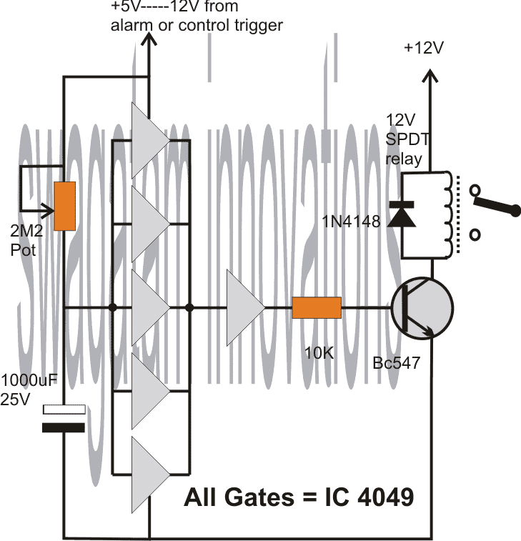
The circuit employs the IC4049 for the required NOT gates which are configured as voltage comparators.
The 5 gates in parallel form the sensing section and provides the required time delay trigger to the subsequent buffer and the relay driver stages.
The control input is acquired from the alarm output as indicated in the above description. This input becomes the switching voltage for the proposed timer circuit.
On receiving this trigger, the input of the 5 NOT gates are initially held at logic zero because the capacitor grounds the initial trigger via the 2m2 pot.
Depending upon the 2m2 setting, the capacitor starts charging up and the moment the voltage across the capacitor reaches a recognizable value, the NOT gates revert their output to logic low, which is translated as a logic high at the output of the right single NOT gate.
This instantly triggers the connected transistor and the relay for the required delay output across the relay contacts.
The 2M2 pot may be adjusted for determining the required delays.
Circuit Diagram



Questions & Answers
Good evening Sirji,
I have an Led wall clock powered by Ac outlet. But due to frequent power cuts in my area, the power adapter in that clock started mis-behaving, with numbers blinking indefinitely. But if the cord is removed and the clock is left in off condition for few hours, it resumes its normal function on connection. As soon as the power arrives this problem is seen. If I remove the cord just after the power outage and connect it few minutes after the power arrival then everything is normal. I had read about input power surge current on your site and tried to solve that problem by soldering NTCs on each AC input wire just before the adapter and it did its work pretty well but in due time (may be due to continuous heating effect of AC), that same problem has started showing up again. Now I am thinking of using a delay on or off timer, just before that adapter so that when the power arrives, the internal circuitry would remain in off condition for few seconds or minutes and after that the power to the clock can continue as usual.
Do I have any other option left to solve this problem? Or may be my NTC option had something better way to solution?
Please advise Sirji!!
Hi Maddy,
Is the adapter output perfectly regulated at 1.5V? If not please try to add a 1.5V DC regulator and also add a 1000uF capacitor across the output terminals along with a 0.1uF capacitor, and then check the results…this might avoid the need of an extra delay timer circuit.
If you still want to use a delay timer, let me know, I will suggest the right delay ON design for you…
Good morning Sirji,
Should both the capacitors need to be connected across the output section? If doing this much can remove the need for my Delay timer, then I would prefer to apply your suggestion first!!
Moreover, as I said, the clock works normally until the power outage & recurring surge current EVENT. In my view, this hints that the adapter is working pretty normally. If this particular surge current can be stopped from entering the adapter just for few seconds then I think the clock circuit life can be extended. At present, I have two values of NTCs in my pocket. One is 10D9 while other is 102 ie 1K ohms. The value of NTCs soldered on the adapter were 10D9. Do you think that by changing them with 102 might save the internal cicuitry from the surge current. I should add to this comment that these components will be facing the AC current’s Burning HEAT continuously until the next power outage.
It’s really painful to reveal ONLINE that some stupid person is playing with the Govt electric supply lines. He is seen to do this anytime, be it a day or a night. As far as my observation has confirmed, this person belongs to the Electric board only and is a locale. And shuts the supply of whole area just to avoid the entry of electricity theft event in the sensitive instruments that can take note of the sudden change in power consumption in that area. He is seen to resume power either within 5 minutes or 20 minutes. That is to say that if he is helped by someone then the power is resumed within few minutes. Otherwise, he goes to his home, makes an illegal connection and returns to resume power exactly after 20 minutes. This problem has been seen for few months only. And seems like people already know about his doings.
Anyways, his idotry is taking a toll on my clock. So what is your suggestion for this particular problem? I don’t want to make any mess outside about my observations. Please advise.
Thank you!!
Thanks Maddy, for the detailed explanation,
In that case let’s give the delay timer circuit a try, since the results are already confirmed from your side.
Please tell me the output voltage specifications from the adapter, then I will design it accordingly…
Good evening Sirji,
Sorry for the delayed response. There is an important update here. As per your instructions, I decided to measure the output voltage of the Adapter. Upon opening the cabinet and switching the Adapter on, it started giving same problem. So in a minor sense, the cause of infinite blinking might have started from outside but here without any surge current, I was having this blinking problem. So there has to be atleast one problem hiding in the Adapter only. A casual look of the circuit doesn’t reveals anything but a closer observation says that there were two polarised caps in series on the input side, just after the rectifier section. And they didn’t look identical, although both were rated at 10uF, 250V. One of them had it’s outer cover looking tight and the Aluminium cover at the top had its triangle pushed outside. So I took chance and rushed to market for buying that value. Luckily, I got a higher value rated for 450v. I replaced the faulty cap with the new one. And damn, MISSION ACCOMPLISHED!!
I tried multiple times switching on/off but nope, this time there wasn’t any blinking or any other problems.
I thank you for pushing for finding the Adapter output. In the meantime, the clock is working flawlessly. And I’m waiting for the next power cut so that I could decide whether to go for a Timer or not!!
Thank you, Sirji!!
That’s amazing Maddy, You are most welcome… I am super glad the problem is solved now from the root. All the best to you..
If the problem somehow repeats during a real power cut, do not hesitate to tell me here, we will investigate it and dig it out again…
Good Morning Sirji,
Last evening my Ajanta Led clock failed the Surge current test. More than that, the clock refused to start even after 2 hrs of disconnection. But when connected in early morning, it again started working normally. I still have the option to replace the second capacitor from the capacitor series duo with the same 450v volts capacitor because I had bought two pieces from the market.
In the meantime now, it seems to me like I should better equip the clock with a Delay timer because the clock has been hung little higher than the height my hand can reach and every time I need to bring a chair to make or remove the connection during Surge failure. And that Idiot disturbs my clock two times in 24 hrs everytime for making or removing the illegal connection. So far, so good. But now I’m done with this process.
My last observation says that the Adapter was of 5 volts but the +5/-5 mark at the Adapter output side creates a confusion for me because there were just two wires going towards Display board and one was black while the other was of some other color. And more than that if it were +5/-5 then there should be a third ground wire present but it was not there. And I don’t think an Led clock would require a dual supply. Please help Sirji.
Thank you for your precious time and advice. And if possible, please avoid using a Relay in your design because of limited space availability.
Thanks again.
Hi Maddy,
Did you measure the output voltage of the adapter with a digital multimeter and with a small load connected? If not please do it. Also, I think a wall clock normally requires 1.5V DC, so 5V can be too high for it.
I can definitely give you the delay timer circuit but before that please measure the adapter voltage because I still think that it can simply solved with a good regulated power supply….and remember a delay timer will not help the wrong power being supplied to the clock which can be detrimental to the clock overtime.
Alternatively I would advise to build a new, transformer based power supplly, with a regulated output, if you want I can help you with this power supply design.
Good Evening Sirji,
It might be some mistake on my part that I still feel sorry and incapable of not being able to clear the complete picture for you.
It is a Digital Led clock with red coloured segmented displays and not real tiny Leds. It shows Date, Time, Weekdays, Surrounding temperature (in ℃) and can be adjusted to display either 12 or 24 hr clock system. All of this running on two general purpose pen batteries of 1.5V each. Only the display section is powered by the Adapter, otherwise the internal clock circuitry keeps running on batteries, independently of outside power.
I remember clearly that after your advice when I opened the back cover and connected it to power supply, it started blinking. Being suspicious of a failing Adapter, I measured it’s output voltage, that was nearly 4.5+ volts and not +5/-5 as indicated by the Adapter board, otherwise my Multimeter should have read nearly 10 volts as the voltage difference between the output pins. That’s surprising for me too. I just forgot to mention this.
Once the display settings are done, the clock simply works like a Computer cmos system. If the power is available then prefixed set of numbers will be displayed otherwise the internal clock will keep ticking without any external supply. It seems like when the power is available then no battery power is taken because I remember of changing the internal batteries nealy two years ago.
Now as for your Transformer power supply comment, I must say I have seen a small transformer on the Adapter board myself.
Anyways, luckily we didn’t had any power cut today. But as the weekend is coming, that idiot has become so courageous that he nowadays plugs his illegal connection for whole weekend altogether. That is why I want to add the additional security layer of a Delay timer permanently.
Luckily, I have got a solution from your site only, titled as “Delay Timer for Refrigerator” where the connected load is survived by using a Transformer-less supply and few passive components like Bjts and Triac. For that purpose, I just need to measure the power being taken by the display section.
I hope you got the full picture now.
Please advise and Thank you again.
Good Morning Maddy, and thank you for the detailed explanation.
OK, I completely understand now.
So here’s the delay timer which you can try, without a relay. I would not not recommend a transformerless power supply because they cannot provide higher currents than 100mA and is too risky due their non-isolated topology.:
https://www.homemade-circuits.com/wp-content/uploads/2026/08/delay-timer-without-relay.jpg
Good Noon Sirji,
Thank you for your prompt response and I must say that I have almost all the components required therein.
But a few questions arise here like the company has chosen to supply the board with +5v Adapter, so is it suitable to feed it with +12v supply?
Can this supply replace the +5v adapter already sitting inside?
Can we replace BD140 with a suitable pnp replacement?
It would had been more suitable if there could have been some solution that can be adjusted in the pre-existing +5v system, while a +12v supply would require a separate 12v Adapter for the given circuit.
So that arrangement would expand to +12v adapter > Given circuit > Display panel!!
And this proposed system would require a dedicated adapter which would be working 24×7×365 and I don’t think any adapter can handle that much load unless designed by the manufacturer itself.
Alternatively, some arrangement could be deviced that could act just like a savior for the +5v adapter that would just delay the supply for few seconds and nothing more than that!! Even my NTC soldered before the Adapter input showed a little expansion just due to the heating effect of AC current.
Now my preference for the “Delay Timer for Refrigerator” was simply due to its simplicity and compactness. Moreover, it would have removed the need for the +5v adapter too. And I don’t think the clock would require even a 100mA current. Because the more the current required by the panel, the more chances exist that it should have been supplied with a heatsink.
I respect your concern for my safety and I can assure you that I can leave the Transformer-less circuit for many minutes alone for discharging the high voltage stored somewhere. And even I fear working on live wires. But the situation here demands such solution only!!
If you require then I would readily measure the current and voltage being consumed by the display panel.
Please advise Sirji!!
Sorry for annoying you with my lengthy requests!!
Thank you!!
Good Morning Maddy,
No problem at all…If you are interested to use the delay ON timer as explained in the refrigerator protector article, you can use it. You can replace the relay with your clock display, and replace the 12V zener with a 5V zener diode.
Good morning Sirji,
And a very happy 80th Independence Day to you.
Sorry to disturb you again!
I have just one difficulty left. I hope you won’t mind my lengthy questionnaires.
Until now I have few options remaining, viz.,
1- Experimentation by changing the remaining 10uF and see what happens!!
2- Experimenting with NTCs of higher values.
3- Modifying & making a (NEW) ckt of Refrigerator Protector ckt.
4- Modifying & making the above proposed (NEW) ckt by using a Bridge Recifier for a reduced voltage of 5 volts.
The last option is my final question from you!! Can I use a Bridge Rectifier combined with a 5v Zener voltage regulator to replace the Adapter. If so what modifications need to be adjusted in above ckt. I’m doing all this just to keep my expenditures as low as possible, because as I said before that I already have almost all the components required there, (except BD140).
Please bear with me.
Thankx again!!
Good Morning Maddy,
Yes a bridge rectifier can be used for the transfomerless delay ON timer circuit. You can implement as shown in thte following diagram, the zener diode can be a 5V zener if the load demands a 5V supply…:
https://www.homemade-circuits.com/wp-content/uploads/2026/08/tramsformerless-powered-delay-ON-timer-circuit.jpg
Good evening Sirji,
I was going through different solutions given by you on Refrigerator delay on ckt page where in a question by Sajida Mahmood, regarding sudden switch Off and switch On of electricity, the ckt wasn’t responding fairly. There you suggested adding a PNP transistor and a 4k7 bleeder resistor for discharging all the capacitors quickly. So my question is, I too face similar situation some times. So can I add similar modifications to the ckt proposed by you for my peculiar problem?
And apart from all this, I have a few suggestions for your site, to make our navigation through different sections over any page. Please include a Floating menu button on every page that shows commands like-
1- Move to bottom
2- Move to Index
3- Move to Q&A section
That would save us Readers a lot of swiping time.
And it’s normal that you log-in as an Admin, so it might be that you haven’t seen these verticle parallel lines eating our writing space, which seems unnecessary because the same thing can be done by a single horizontal line.
Please think over it.
And Thank you for your time and patience!!
Good evening Maddy,
Actually I won’t recommend complicating the BJT based circuit, instead i would suggest you the following 555 based delay OFF circuit. This will give you precision timing output, and will not be affected by any other hidden side effects.
https://www.homemade-circuits.com/wp-content/uploads/2026/08/555-delay-off-timer-circuit.jpg
Please try this with 12V DC first, if everything goes well, then we can replace the 12V DC with our capacitive power supply.
And regarding your other suggestions to make the floating navigations and removing the comment thread getting narrower on each reply, I will definitely try to solve them as quickly as possible. Thank you for providing me with these critical issues, it is much appreciated.
Let me know how the circuit works, if you still insist on the BJT based design, I will try to upgrade it for you accordingly…
Yes, I’ve set it up, but I wanted to confirm with you. Thank you for the helpful information. If you could draw a simple diagram showing how to replace the relay with an N-channel MOSFET, that would be a great help.
Sure, you can follow the below given ideal MOSFET connection setup:
https://www.homemade-circuits.com/wp-content/uploads/2026/05/connect-a-MOSFET.jpg
I haven’t used MOSFETs before, and I’m not sure whether I should use an N-channel or a P-channel MOSFET, or what the correct connection is. I’m using Pin 3 (Q14) on both CD4060s; is this believed to be correct for the timing I’m aiming for, so I don’t have to use very large resistors and capacitors? I calculated the timing (though I’m not entirely sure) and want to use 5 different resistors (1M, 1.2M, 1.5M, 1.8M, 2.4M) for the astable circuit and 5 (100K, 180K, 250K, 420K, 600K) for the monostable circuit, selected via two rotary switches (1×5), and keep the capacitor fixed at a low value (470 nF) for greater accuracy. If you are familiar with this and have time, I would appreciate your help.
Translated with DeepL.com (free version)
Yes Pin 3 (Q14) of the CD4060 looks correct here if long timing delays are needed, because then RC values can stay reasonably smaller instead of using extremely huge resistors or capacitors everywhere.
That idea of using rotary switches with different resistor values and one fixed 470nF capacitor also looks good actually.
For electronic switching of those timing resistors, an N-channel MOSFET is generally easier to use if switching is done on the ground side…
And yep, those resistor ranges you selected seem reasonable for experimenting with the CD4060 oscillator section..
Hello Mr. ____
I’m interested in the great offer on your website. I’m trying to build a timer that turns on a machine at specific intervals and keeps it running for a specific number of minutes, based on settings I’ve configured in advance. I have selected two integrated circuits, the CD4060, one configured as an astable multivibrator and the other as a monostable multivibrator. The machine’s activation times have 5 options (2, 2.5, 3, 4, or 5 hours), and the duration it will remain active until it shuts off has 5 options (10, 15, 20, 30, or 40 minutes). Instead of a Relief, I would like a MOSFET. The machine has a power consumption of ~10W (24V/~0.5A). Is there a schematic available?
Yannis (John) from Greece.
Translated with DeepL.com (free version)
Hi, I guess you have already configured the 4060 circuit, in that case do you want only the MOSFET stage?
hi Mr. Swagatam.
I’m Indra, I have a 3d printer machine. I want to make a timer circuit off with an adjustable time. I am interested in your timer circuit using the Triac BT 36 so it doesn’t use relays or DC voltage. how does the circuit work so that after the button is pressed, the AC voltage on the load will be off at a selectable time.
thanks for your reply..what in left side?vin? mean dc voltage?
Yes, your DC input through the push button…
Thanks for your reply..maybe i will try your circuit with triac bt 36,no DC, no relay, coz i want simplest circuit for off timer. if you have another suggestion for my need..just mail me :)..thanks for your help
Ok great, you can definitely use my design using BT136 triac, as given below, let me know if you have any issues with the circuit…:
https://www.homemade-circuits.com/wp-content/uploads/2012/05/triac-timer.png
Hi Indra,
For a short delay you can do it quickly and safely by employing the following concept:
https://www.homemade-circuits.com/wp-content/uploads/2025/11/Triac-load-control-with-timer.jpg
If you need relatively longer delays then the LED side might require a BJT based timer stage…
Hi there,
I have been tasked with creating something to allow a button to be pressed, there be a 5 second delay(ideally with a visual countdown) and then power up a light to give one single flash and then reset to be used again. All the products/circuits i seem to find all want to delay and then switch on, not flash. Is such a thing possible ? Or am i fighting a losing battle ?
Even just a yes it’s possible would inspire me to keep reaseaching although its been 20+ years since i’ve worked with circuit boards.
hope you can help.
thanks
Richard
Hi, there’s one mistake in the previous circuit diagram which i gave you.
Please make sure to add a diode in series with the brown colored wire which connects the collector of the right side BC557 with the base of left side BC557. Cathode towards left side BC557 and anode towards right side BC557…
And also please reduce the positive to base 10k resistor value of the left side BC557 to 4.7k.
Hi, do you need this circuit using only transistors or an IC will also do? Because an IC can work more efficiently…
Hi there, thank you for responding.
I’m looking for the most reliable and efficient way to do this, so i guess an IC would be better however i would go with whichever way you think is best.
thanks
Richard
Ok, I have designed it with transistors, you can check it out below. The right/bottom transistor is BC547, Rx and Cx must be adjusted to get the required 5 second ON time delay.
https://www.homemade-circuits.com/wp-content/uploads/2025/07/single-flash-and-then-reset-to-be-used-again.jpg
Wow, thank you for that. I will start assmbly and let you know how it goes.
Thanks again
Richard
Sure, no problem, all the best to you…please make and test the stages step-wise.
YOUR WORKS ARE AWESOME BROTHER , AND HELPING OTHERS , ITS WORTH A VISIT
Thanks bro, I appreciate your kind words and glad you liked this site…
Dear Sir,
on “Delay ON Timer Circuit Working Details”, C2 is not discharged quickly, so if mains power fails and returns before C2 is discharged, then delay-on time will be shortened.
Any suggestion for the above problem ?
TNX
Yorgos
GREECE
Hi Yorgos, please try the following modification, and let me know if it works or not:
https://www.homemade-circuits.com/wp-content/uploads/2025/06/delay-ON-with-quick-discharge.jpg
I am looking for a simple circuit to control a start winding of a compressor motor. The start coil and capacitor are connected in series. And use a common 120v which is shared with the run winding and capacitor in series.
Can you please provide a basic simple circuit which uses a transistor or mosfet to turn off the start winding after a few seconds? Please try and make the circuit as simple as possible only using resistors, diodes, capacitors, and an npn mosfet/transistor.
Since a compressor motor is an AC system, MOSFETs or BJTs might not work, so you might have to use a triac instead. You can try the following design and see if it works or not:
https://www.homemade-circuits.com/wp-content/uploads/2025/04/capacitor-start-motor-yriac-switching.jpg
Hi Swagatam,
I’ve been looking for a similar solution: a fast spin-up circuit for a “dimmed” universal motor. AKA overshoot at switch-on. It’s a pump and when the pressure drops below a set threshold the motor needs to recover it first (also spinning up and starting to move the water in the pipes as well) then to fall back to the operating power/RPM. It takes about 2..3 secs.
I’ve recognized some parts of this circuit at one of your previous posts: https://www.homemade-circuits.com/simple-triac-triggering-circuits-explained/#:~:text=Figure%202
I haven’t found anything similar to this circuit. Also, I don’t seem to get how a 10uF capacitor could produce efficient delay. Neither I see the purpose of the capacitor at the very top of this schematics.
May I also note that my mains is 240VAC and I already have a BTA06 (I_G=5..50mA, instead of 10..25mA of a BT136) dimmer PCB present, connected to the pump motor.
Any help much appreciated.
Thanks in advance, KGy
Thanks KGy,
Are you referring to the following circuit? In this circuit, the delay capacitor is rated at 100uF, and there’s no capacitor at the top…please let me know which diagram you are actually referring to:
https://www.homemade-circuits.com/wp-content/uploads/2021/10/AC-POWER-SWITCH-whose-triac-can-be-triggered-with-line-derived-DC.jpg
Hi Swagatam,
Thank you very much for coming back to me. You are a star.
Yes, that’s the one. The timing cap is electrolytic, not poly. Furthermore, -if I’m right- it delays the switch-on.
What I need is additional circuit to the basic triac dimmer that opens the gate for a full-cycle for a couple of seconds.
Where I see the problem lies is that a delay and a trigger circuits need to work alongside.
My best guess would be to utilize a diode-bridge for this.
There are plenty schematics for soft-starters but I need the opposite, which I believe is more complicated.
I hope with it I managed to clarified my needs / circumstances.
Thank you so much,
KGy
P.S. I believe this line of my comment is ambiguous/needs clarification: > I haven’t found anything similar to this circuit.
I meant the one you’ve posted here/I’m replying to. I didn’t manage to find anything similar on the Internet. Neither using the image nor the keywords “start.winding” “compressor”, etc.
Thank you KGy,
Though not 100% sure, I think the following configuration can be used to keep the load dimmed normally, and boost the power only during power switch ON, for a couple of seconds, you can try this and let us know how it goes:
https://www.homemade-circuits.com/wp-content/uploads/2025/05/triac-switch-ON-boost.jpg
sir mujhe ek 24 volt se chalane wala delay circuit ki jarurat hai jo 5 se 20 secand tak voltage delay kar sake
bina trigar switch ke
Ashish, you can try the following circuit, just make sure to change the relay coil voltage to 24V
https://www.homemade-circuits.com/wp-content/uploads/2022/04/delay-ON-timer.jpg