The lead acid battery charger circuits I have explained in this article can be used for charging all types of lead acid batteries at a specified rate.
This article explains a few lead acid battery charger circuits with automatic over charge, and low discharge cut off. All these designs are thoroughly tested and can be used to charge all automotive and SMF batteries up to 100 Ah, and even 500 Ah.
Introduction
Lead acid batteries are normally used for heavy duty operations involving many 100s of amps. To charge these batteries we specifically need chargers rated to handle high ampere charging levels for long periods of time.
Lead acid battery charger are specifically designed for charging heavy duty batteries through specialized control circuits.
The 5 useful and high power lead acid battery charger circuits presented below can be used for charging large high current lead acid batteries in the order of 100 to 500 Ah, the design is perfectly automatic and switches of the power to the battery and also itself, once the battery gets fully charged.
UPDATE: You may also want to build these simple Charger circuits for 12 V 7 Ah Batteries, check them out.
What does Ah Signify
The unit Ah or Ampere-hour in any battery signifies the ideal rate at which the battery would be fully discharged, or fully charged within a span of 1 hour.
For example, if a 100 Ah battery was charged at 100 ampere rate, it would take 1 hour for the battery to get fully charged. Likewise, if the battery was discharged at 100 ampere rate, the backup time would last not more an hour.
But wait, never try this, as charging/discharging at the full Ah rate can be disastrous for your lead acid battery.
The unit Ah is there only to provide us with a benchmark value which can be used for knowing the approximate charge/discharge time of the battery at a stipulated current rate.
For example when the above discussed battery is charged at 10 ampere rate, using the Ah value we can find the full charge time through the following formula:
Since charging rate is inversely proportional to the time, we have:
Time = Ah Value / Charging Rate
T = 100 / 10
where 100 is the Ah level of the battery, 10 is the charging current, T is the time at the 10 amp rate
T = 10 Hours.
The formula suggests it would ideally require around 10 hours for the battery to get optimally charged at 10 amp rate, but for a real battery this may be around 14 hours for the charging, and 7 hours for the discharging.
Because in real world even a new battery won't work with ideal conditions, and as it ages the situation may get even worse.
Important Parameters to be Considered
Lead acid batteries are expensive, and you will want to ensure that it lasts as long as possible. So please do not use cheap and untested charger concepts, which may look easy but may harm your battery slowly.
The big question is, is ideal method of charging a battery essential? The simple answer is NO. Because when we apply ideal charging method as discussed in "Wikipedia" or "Battery University" websites, we try to charge the battery at its maximum possible capacity.
For example, at the ideal 14.4 V level your battery may be fully charged, but it can be risky to do this using ordinary methods.
To achieve this without risks you may have to employ an advanced charger step charger circuit, which can be difficult to build, and might require too many calculations.
If you want to avoid this, you can still charge your battery optimally (@ around 65%) by ensuring that the battery is cut-off at a little lower level.
This will allow the battery to be always under less stressful condition. The same goes for the discharge level and rate.
Basically it must have the following parameters for a safe charging which does not require special step chargers:
- Fixed Current or Constant Current (1/10th of Battery Ah Rating)
- Fixed Voltage or Constant Voltage (17% higher than Battery Printed Voltage)
- Over Charge Protection (Cut-OFF when Battery gets charged to the above level)
- Float Charge (Optional, not compulsory at all)
If you do not have these minimum parameters in your system, then it may slowly degrade the performance and damage your battery, reducing its back up time drastically.
- For example, if your battery is rated at 12 V, 100 Ah, then the fixed input voltage should be 17% higher than the printed value, that's equal to around 14.1 V ( not 14.40 V, unless you are using a step charger).
- Current (ampere) ideally should be 1/10th of the Ah level printed on the battery, so in our case this can be 10 amperes. A slightly higher Amp input can be fine since our full charge level is already lower.
- Charging auto cut off is recommended at the above mentioned 14.1 V, but it's not compulsory since we already have the full charge level slightly lower.
- Float Charge is a process of reducing the current to negligible limits after the battery has reached full charge. This prevents the battery from self discharging and holds it at the full level continuously until it's removed by the user for usage. It is completely optional. It may be necessary only if you are not using your battery for long periods of time. In such cases too it's better to remove the battery from the charger and top it up occasionally once every 7 days.
The easiest way to get fixed voltage and current is by using voltage regulator ICs, as I have explained below.
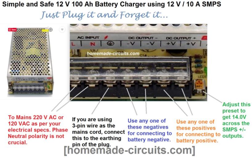
Another easy way is to use a ready made 12 V SMPS 10 Amp unit as the input source, with an adjustable preset. The SMPS will have a small preset at the corner which can be tweaked to 14.0 V.
Remember you will have to keep the battery connected for at least 10 to 14 hours, or until your battery terminal voltage reaches 14.2 V.
Although this level may look slightly undercharged than the standard 14.4 V full level, this ensures your battery can never get over charged and guarantees a long life for the battery.
All the details are presented in this infographic below:
However, if you are an electronic hobbyist and interested to build a full fledged circuit with all the ideal options, in that case you can go for the following comprehensive circuit designs.
[New Update] Current Dependent Battery Auto Cut OFF
Normally, a voltage detected or voltage dependent automatic cut off is used in all conventional battery charger circuits.
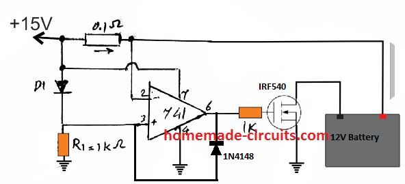
However, a current detection feature can be also employed for initiating an auto cut off when the battery reaches its most optimal full charge level. The complete circuit diagram for the current detected auto cut off is shown below:
How it Works
The 0.1 Ohm resistor acts like a current sensor by developing an equivalent potential difference across itself .
The value of the resistor must be such that the minimum potential deference across it is at least 0.3V higher than the diode drop at pin 3 of the IC, until the battery has reached the desired full charge level.
When the full charge is reached this potential should come down below the diode drop level.
Initially , while the battery is charging, the current draw develops a negative potential difference of say -1V across the input pins of the IC.
Which means that the pin 2 voltage now becomes lower than the pin3 voltage by at least 0.3V. Due to this pin 6 of the IC goes high allowing the MOSFET to conduct and connect the battery with the supply source.
As the battery charges to its optimal level, the voltage across the current sensing resistor drops to a sufficiently lower level causing the potential difference across the resistor to become almost zero.
When this happens, pin 2 potential rises higher than pin3 potential, causing pin 6 of the IC to go low, and switching OFF the MOSFET.
The battery thus gets disconnected from the supply disabling the charging process. The diode connected across pin 3 and pin 6 locks or latches the circuit in this position until power is switched OFF and ON again for a fresh cycle.
The above current dependent charging circuit can be also expressed as given below:
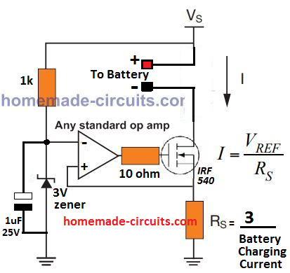
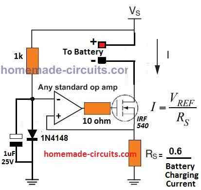
When power is switched ON, the 1 uF capacitor grounds the inverting pin of the op amp causing a momentary high at the op amp output, which switches ON the MOSFET. This initial action connects the battery with the supply via the MOSFET and the sense resistor RS.
The current drawn by the battery causes an appropriate potential to develop across RS which raises the non-invering input of the op amp above the reference inverting input (3V).
The op amp output now latches ON and charges the battery, until the battery is almost fully charged. This situation reduces the current through RS such that the potential across it drops below 3 V reference and the op amp output turns low, switching OFF the MOSFET and the charging process for the battery.
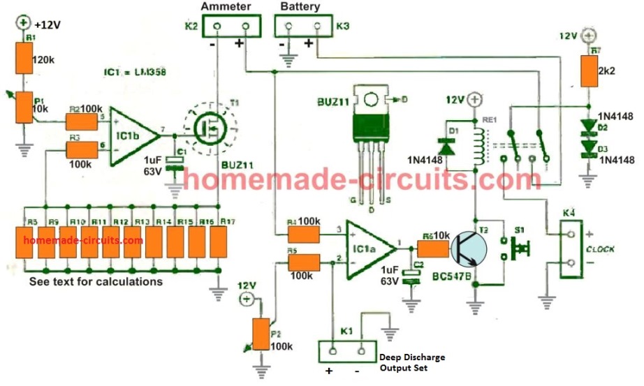
The above current dependent battery charging system design can be understood more elaborately in the below comprehensively drawn diagram, which can be used for charging very high capacity batteries in the order of 200 Ah to 500 Ah very safely:
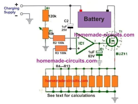
Adjust the 10 k preset so that just around 0.3 V or 0.4 V is available at the (-) input of the op amp, and set the R4---R13 resistor bank such that their net resistance is:
R = 1 / Max charging current.
Suppose the battery is 100 Ah, then the max charging current will be 10 amps, therefore,
R = 1 / 10 = 0.1 Ohms
Calculating the Parameters Accurately to Improve the above Design
The gate resistor affects the charging and discharging of the MOSFETs gate capacitance, which determines the switching speed. The formulas and explanation for improving the circuit are given as shown below:
Sense Resistor (Rs): We can calculate the charging current through the sense resistor:
I = Vref / Rs
Where:
I is the battery charging current.
Vref is the reference voltage applied to the op-amp's non-inverting input.
Rs is the sense resistor value.
To calculate Rs we can use the following formula:
Rs = Vref / I
For example if Vref = 0.6 V and the target charging current is 1 A:
Rs = 0.6 / 1 = 0.6 ohms
The power dissipation across Rs is given by: PRs = I2 * Rs
For a 1 A charging current:
PRs = 12 * 0.6 = 0.6 W
Please Choose a resistor with a power rating of at least 1 W for safety margin.
Reference Voltage (Vref): You must adjust the Vref to be stable and can be generated using a precision voltage reference IC or a resistor-divider network with a Zener diode. If you want the charging current needs to be adjustable then a potentiometer can be used to vary Vref.
Capacitor (1 µF): This capacitor stabilizes the op-amp input. It s value can be estimated using the time constant:
Tau = R * C, Where the Tau is the time constant, the R is the equivalent resistance seen by the capacitor and C is the capacitance value.
Make sure to Use a low ESR ceramic capacitor to ensure proper filtering.
MOSFET (IRF540): The IRF540 has a threshold voltage (Vgs(th)) of ~4 V. You must ensure that the op-amp can supply sufficient gate voltage for full enhancement. If the op-amp supply voltage is low (e.g., 5 V) then you must replace the IRF540 with a logic-level MOSFET like IRLZ44N.
Diode (1N4148): This diode ensures the proper operations but for better efficiency it can be replaced with a Schottky diode which has a lower forward voltage drop.
Op-Amp Selection: You must choose an op-amp with rail-to-rail output if the gate drive voltage of the MOSFET is close to the supply voltage. The Examples include LM358 (basic design) or TLV2372 (for better performance).
Example Calculation:
Let us Assume that a 12 V battery with a desired charging current of 1 A:
Vref = 0.6 V Rs = 0.6 / 1 = 0.6 ohms (use a 1 W resistor or higher)
Power dissipated in Rs:
PRs = 12 * 0.6 = 0.6 W
Then you must Choose the IRLZ44N as the MOSFET (logic level). Use a 1 µF ceramic capacitor for stabilization.
1) Using a Single Op amp
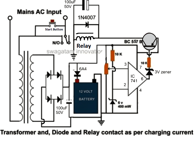
Looking at the first high current circuit for charging large batteries, we can understand the circuit idea through the following simple points:
There are basically three stages in the shown configuration viz: the power supply stage consisting of a transformer and a bridge rectifier network.
A filter capacitor after the bridge network has been ignored for the sake of simplicity, however for better DC output to the battery one can add a 1000uF/25V capacitor across the bridge positive and negative.
The output from the power supply is directly applied to the battery which requires to be charged.
The next stage consists of an opamp 741 IC voltage comparator, which is configured to sense the battery voltage while it is being charged and switch its output at pin #6 with the relevant response.
Pin #3 of the IC is rigged with the battery or the supply positive of the circuit via a 10K preset.
The preset is adjusted such that the IC reverts its output at pin #6 when the battery becomes fully charged and reaches about 14 volts which happens to be the transformer voltage at normal conditions.
Pin #2 of the IC is clamped with a fixed reference via a voltage divider network consisting of a 10K resistor and a 6 volt zener diode.
The output from the IC is fed to a relay driver stage where the transistor BC557 forms the main controlling component.
Initially, power to the circuit is initiated by pressing the "start" switch. On doing this, the switch bypasses the contacts of the relay and powers the circuit momentarily.
The IC senses the battery voltage and since it will be low during that stage, the output of the IC responds with a logic low output.
This switches ON the transistor and the relay, the relay instantly latches the power via its relevant contacts such that now even if the "start" switch is released, the circuit remains switched ON and begins charging the connected battery.
Now as the battery charge reaches about 14 volts, the IC senses this and instantly reverts its output to a high logic level.
The transistor BC557 responds to this high pulse and switches OFF the relay which in turn switches of the power to the circuit, breaking the latch.
The circuit gets completely switched OFF until the start button is pressed once again and the connected battery has a charge that's under the set 14 volt mark.
How to set up.
It's very easy.
Do not connect any battery to the circuit.
Switch ON power by pressing the start button and keep it depressed manually, simultaneously adjust the preset such that the relay just trips or switches OFF at the given rated transformer voltage which should be around 14 volts.
The setting is complete, now connect a semi discharged battery to the shown points in the circuit and press the "start" switch.
Due to the discharged battery, now the voltage to the circuit will drop under 14 volts and the circuit will instantly latch, initiating the procedure as explained in the above section.
Circuit Diagram for the proposed battery charger with high ampere capacity is shown below
2) 12V, 24V / 20 amp Charger Using two opamps:
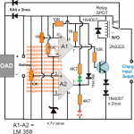
The second alternative way of achieving battery charging for a lead acid battery with high amperage can be observed in the following diagram, using a couple of op amps:
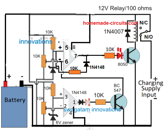
The working of the circuit can be understood through the following points:
When the circuit is powered without a battery connected, the circuit does not respond to the situation since the initial N/C position of the relay keeps the circuit disconnected from the charging supply.
Now suppose a discharged battery is connected across the battery points. Let's assume the battery voltage to be at some intermediate level, which may be between the full charge level and the low charge level.
The circuit gets powered through this intermediate battery voltage. As per the setting of the pin 6 preset, this pin detects a low potential than the pin 5 reference level. which prompts its output pin 7 to go high.
This in turn causes the relay to activate and connect the charging supply to the circuit and the battery via the N/O contacts.
As soon as this happens, the charging level also drops to the battery level and the two voltages merge at the battery voltage level. The battery now begins charging, and its terminal voltage begins increasing slowly.
When the battery reaches it full charge level, the pin 6 of the upper opamp becomes high than its pin 5 causing its output pin 7 to go low, and this switches off the relay, and the charging is cut off.
At this point another thing happens. The pin 5 is connected to the negative potential at pin 7 via the 10k/1N4148 diode, which further lowers the pin 5 potential compared to pin 6.
This is called hysteresis, which ensure that even if the battery now drops to some lower level that won't trigger the op amp back to charging mode, instead the battery level now has to drop significantly down until the lower op amp is activated.
Now, suppose the battery level keeps dropping due to some connected load, and its potential level reaches the lowest discharge level.
This is detected by pin 2 of the lower op amp whose potential now goes below its pin 3, which prompts its output pin 1 to become high and activate the BC547 transistor.
The BC547 grounds the pin 6 of the upper op amp competely. This causes the hysteresis latch to break due to pin 6 potential dropping below pin 5.
This instantly causes the output pin 7 to go high and activate the relay, which yet again initializes the charging of the battery, and the cycle repeats the procedure as long as the battery remains connected with the charger.
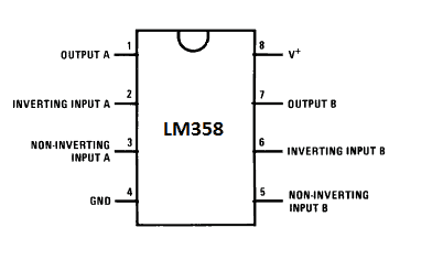
LM358 Pinout
For more auto cut-off charger ideas, you can read this article regarding opamp automatic battery charger circuits.
Video Clip:
The set up of the above circuit can be visualized in the following video which shows the cut off responses of the circuit to the upper and the lower voltage thresholds, as fixed by the relevant presets of the opamps
3) Using IC 7815
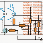
The third circuit explanation below details how a battery may be charged effectively without using any IC or relay, rather simply by using BJTs, I have explained the procedures:
The idea was suggested by Mr. Raja Gilse.
Charging a Battery with a Voltage Regulator IC
I have a 2N6292 . My friend suggest me to make the simple fixed voltage high current DC power supply to charge an SMF battery.
He had given the attached rough diagram. I don't know anything about the above transistor. Is it so ?
My input is 18 volt 5 Amp transformer. He told me to add 2200 uF 50 Volt capacitor after rectification. Is it works ?
If so , is there any heat sink necessary for transistor or/and IC 7815 ? Is it stops automatically after battery reaches 14.5 volt ?
Or any other alteration needed ? Please guide me sir
Charging with an Emitter Follower Configuration
Yes it will work and will stop charging the battery when around 14 V is reached across the battery terminals.
However I am not sure about the 1 ohm base resistor value...it needs to be calculated correctly.
The transistor and the IC both may be mounted on a common heatsink using mica separator kit.
This will exploit the thermal protection feature of the IC and will help safeguard both the devices from overheating.
Circuit Diagram
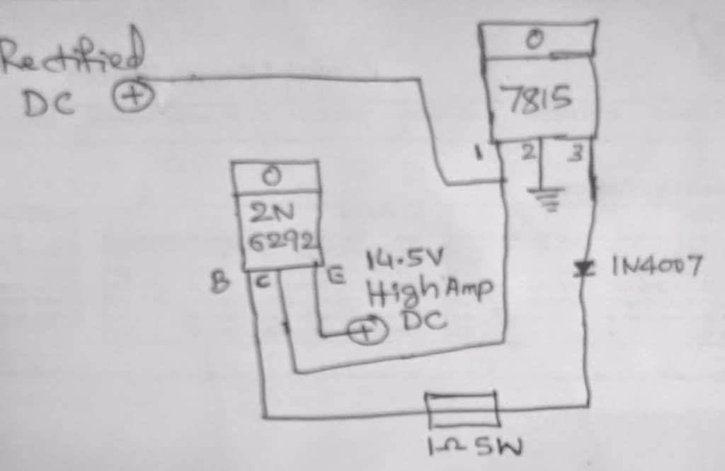
Circuit description
The shown high current battery charger circuit is a smart way of charging a battery and also achieving an auto shut off when the battery attains a full charge level.
The circuit is actually a simple common collector transistor stage using the shown 2N6292 power device.
The configuration is also referred as an emitter follower and as the name suggests the emitter follows the base voltage and allows the transistor to conduct only as long as the emitter potential is 0.7V lower that the applied base potential.
In the shown high current battery charger circuit using a voltage regulator, the base of the transistor is fed with a regulated 15 V from the IC 7815, which ensures a potential difference of about 15 - 0.7 = 14.3 V across the emitter/ground of the transistor.
The diode is not required and must be removed from the base of the transistor in order to prevent an unnecessary drop of an extra 0.7 V.
The above voltage also becomes the charging voltage for the connected battery across these terminals.
While the battery charges and its terminal voltage continues to be below the 14.3 V mark, the transistor base voltage keeps conducting and supplying the required charging voltage to the battery.
However as soon as the battery begins attaining the full and above 14.3 V charge, the base is inhibited from a 0.7 V drop across its emitter which forces the transistor to stop conducting and the charging voltage is cut off to the battery for the time being. As soon as the battery level begins going below the 14.3 V mark, the transistor is switched ON again...the cycle keeps repeating ensuring a safe charging fr the connected battery.
Base resistor = Hfe x battery internal resistance
Here's a more appropriate design which will help to achieve optimal charging using IC 7815 IC
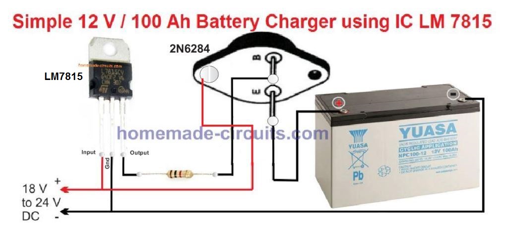
As you can see, a 2N6284 is used here in the emitter follower mode. This is because 2N6284 is a Darlington transistor with high gain, and will enable optimal charging of the battery at the intended 10 amp rate.
This can be further simplified by using a single 2N6284, and a potentiometer as shown below:
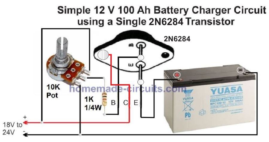
Make sure that you adjust the pot to get a precise 14.2 V at the emitter of the battery.
All the devices must be mounted on large heatsinks.
4) 12V 100 Ah Lead Acid Battery Charger Circuit
The proposed 12V 100 ah battery charger circuit was designed by one of the dedicated members of this blog Mr. Ranjan, I have explained more regarding the circuit functioning of the charger and how it could be used as a trickle charger circuit also.
The Circuit Idea
My self Ranjan from Jamshedpur, Jharkhand. Recently while googling I came to know about your blog, and become a regular reader of your blog. I learned a lot of things from your blog. For my personal use I would like to make a battery charger.
I have a 80 AH tubular batery and a 10 Amps 9-0-9 volts transformer. So I can get 10 amps 18-0 volts if I use the two 9volts leads of transformer.(Transfomer is actually obtained from an old 800VA UPS).
I have constructed a circuit diagram based on your blog. Please have a look on it and suggest me. Please note that,.
1) I am belonging to very rural area hence there is a huge power fluctuation it varies from 50V ~ 250V. Also note that I will draw very less amount of current from the battery( Generally using LED lights during power cuts) approx 15 - 20 Watt.
2) 10amps transformer i think safely charges 80AH Tubular Battery
3) All diodes used for the circuit are 6A4 dides.
4) Two 78h12a used as parallel to get 5+5 = 10 amps output. Although I think Battery must not draw full 10 amps. as it will be in charged condition in day to day use so internal resistance of battery will be high and will draw lesser current.
5) A switch S1 is used thinking that for normal charge it will be kept in off state. and after fully charging the battery it switched to on state to maintain a trickle charge with lower voltage. NOW question is that is this safe for the battery to kept in charge unattended for long time.
Please reply me with your valuable suggestions.
100 Ah battery charger circuit diagram designed by Mr. Ranjan
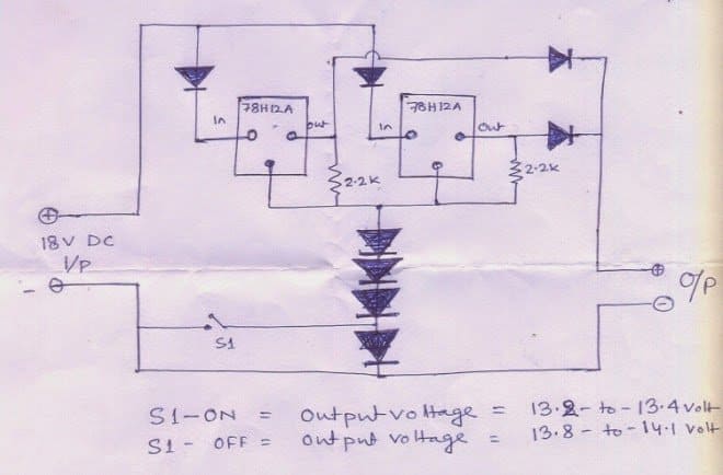
Solving the Circuit Request
Dear Ranjan,
To me your high current VRLA battery charger circuit using IC 78H12A looks perfect and should work as expected. Still for guaranteed confirmation it would be advisable to check the voltage and current practically before connecting it with the battery.
Yes, the shown switch can be used in the trickle charge mode and in this mode the battery can be kept permanently connected without attending, however this should be done only after the battery has been fully charged upto around 14.3V.
Please note that the four series diodes attached with the GND terminals of the ICs could be 1N4007 diodes, while the remaining diodes should be rated well over 10amps, this could be implemented by connecting two 6A4 diodes in parallel at each of the shown positions.
Also, it is strongly recommended to put both the ICs over a single large common heatsink for better and uniform thermal sharing and dissipation.
Caution: The shown circuit does not include a full charge cut-off circuit, therefore the maximum charging voltage should be preferably restricted between 13.8 to 14V. This will ensure that the battery is never able to reach the extreme full charge threshold, and thus remain safe from over charge conditions.
However this would also mean that the lead acid battery would be able to attain only around 75% charge level, nevertheless keeping the battery undercharged will ensure longer life for the battery and allow more charge/discharge cycles.
Using 2N3055 to Charge a 100 Ah Battery
The following circuit presents a simple and safe alternative way of charging a 100 Ah battery using 2N3055 transistor. It also has a constant current arrangement so the battrey can e charged with the correct amount of current.
Being an emitter follower, at the full charge level the 2N3055 will be almost OFF, ensuring the battery is never over charged.
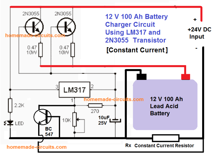
The current limit can be calculated using the following formula:
R(x) = 0.7 / 10 = 0.07 Ohms
Wattage will be = 10 watts
How to Simply Add a Float Charge
Remember other sites may present unnecessarily complex explanation regarding float charge making it complex for you to understand the concept.
Float charge it simply a small adjusted current level which prevents self discharge of the battery.
Now you may ask what's self discharge of the battery.
It's the declining level of charge in battery as soon as the charging current is removed. You can prevent this by adding a high value resistor such as a 1 K 1 watt across the input 15 V SOURCE and the battery positive.
This will not allow the battery to self discharge and will hold the 14 V level as long as the battery is attached to the supply source.
5) IC 555 Lead Acid Battery Charger Circuit
The fifth concept below explains a simple, versatile automatic battery charger circuit. The circuit will allow you to charge all types of lead acid battery right from a 1 Ah to a 1000 Ah battery.
Using IC 555 as the Controller IC
The IC 555 is so versatile, it can be considered the single chip solution for all circuit application needs. No doubt it's been utilized here too for yet another useful application.
A single IC 555, a handful of passive component is all that's needed for making this outstanding, fully automatic battery charger circuit.
The proposed design will automatically sense and keep the attached battery up to date.
The battery which is required to be charged may be kept connected to the circuit permanently, the circuit will continuously monitor the charge level.
If the charge level exceeds the upper threshold, the circuit will cut off the charging voltage to it, and in case the charge falls below the lower set threshold, the circuit will connect, and initiate the charging process.
How it Works
The circuit may be understood with the following points:
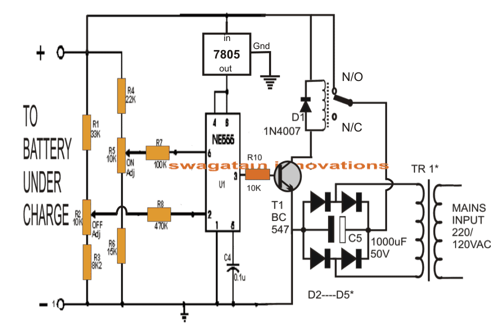
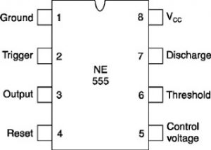
Here the IC 555 is configured as a comparator for comparing the battery low and high voltage conditions at pin#2 and pin#6 respectively.
As per the internal circuit arrangement, a 555 IC will make its output pin#3 high when the potential at pin#2 goes below 1/3 of supply voltage.
The above position sustains even if the voltage at pin#2 tends to drift a little higher. This happens due to the internal set hysteresis level of the IC.
However if the voltage continues to drift higher, pin#6 gets hold of the situation and the moment it senses a potential difference higher than 2/3rd of supply voltage, it instantly reverts the output from high to low at pin#3.
In the proposed circuit design, it simply means that, the presets R2 and R5 should be set such that the relay just deactivates when the battery voltage goes 20% lower than printed value and activates when the battery voltage reaches 20% above printed value.
Nothing can be as simple as this.
The power supply section is an ordinary bridge/capacitor network.
The diode rating will depend on the charging current rate of the battery. As a rule of thumb the diode current rating should be twice that of the battery charging rate, while the battery charging rate should be 1/10th of the battery Ah rating.
It implies that TR1 should be around 1/10th of the connected battery Ah rating.
The relay contact rating should be also selected as per the ampere rating of TR1.
How to set the battery cut off threshold
Initially keep the power to the circuit switched OFF.
Connect a variable power supply source across the battery points of the circuit.
Apply a voltage that may be exactly equal to the desired low voltage threshold level of the battery, then adjust R2, such that the relay just deactivates.
Next, slowly increase the voltage up to the desired higher voltage threshold of the battery, adjust R5 such that the relay just activates back.
The setting up of the circuit is now done.
Remove the external variable source, replace it with any battery which needs to be charged, connect the input of TR1 to mains, and switch ON.
Rest will be automatically taken care of, that is now the battery will start charging and will cut off when its fully charged, and also will get connected to power automatically in case its voltage falls below the set lower voltage threshold.
IC 555 Pinouts
IC 7805 Pinout
How to Set Up the Circuit.
The setting up of the voltage thresholds for the above circuit may be done as I have explained below:
Initially keep the transformer power supply section at the right hand side of the circuit completely disconnected from the circuit.
Connect an external variable voltage source at the (+)/(-) battery points.
Adjust the voltage to 11.4V, and adjust the preset at pin#2 such that the relay just activates.
The above procedure sets the lower threshold operation of the battery. Seal the preset with some glue.
Now increase the voltage to about 14.4V and adjust the preset at pin#6 to just deactivate the relay from its previous state.
This will set up the higher cut off threshold of the circuit.
The charger is now all set.
You may now remove the adjustable power supply from the battery points and use the charger as explained in the above article.
Do the above procedures with lot of patience and thinking
Feedback from one of the dedicated readers of this blog:
Hi, you have made a mistake on preset R2 and R5, they should not be 10k but 100k, I just made one and it was a success, thank you.
As per the above suggestion, the previous diagram may be modified as shown below:
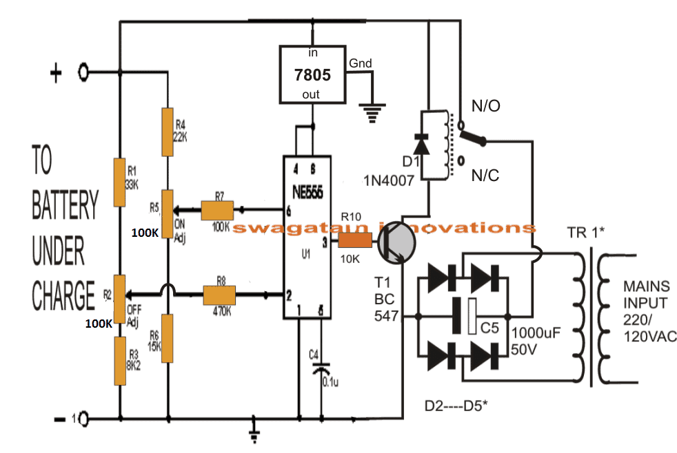
Design Steps for Automatic Lead-Acid Battery Charger using IC 555
Specifications:
- Upper cutoff voltage (V_cutoff): 14.4V (fully charged battery).
- Lower restart voltage (V_restart): 11.8V (recharge threshold).
- IC 555 supply voltage (V_CC): 12V.
Step 1: Voltage Divider for Battery Voltage
The battery voltage must be scaled to match the internal reference levels of IC 555:
- Lower reference: V_CC/3.
- Upper reference: 2 × V_CC/3.
The voltage divider is designed using resistors R1 and R2. The scaled voltage V555V_555V555 is calculated as:
V_555 = V_battery × (R2 / (R1 + R2))For proper operation:
- At V_cutoff (14.4V), V_555 = 2 × V_CC / 3.
- At V_restart (11.8V), V_555 = V_CC / 3.
Use these conditions to calculate R1 and R2
Step 2: Calculations for R1 and R2
For Upper Cutoff (14.4V):
At V_battery = 14.4V, the scaled voltage is:
V_555 = 2 × V_CC / 3
V_555 = 2 × 12 / 3 = 8V
Using the voltage divider formula:
8 = 14.4 × (R2 / (R1 + R2))
R2 / (R1 + R2) = 8 / 14.4 = 0.555
Choose R1 + R2 = 100kΩ (standard value for simplicity):
R2 = 100kΩ × 0.555 = 55.5kΩ
R1 = 100kΩ - 55.5kΩ = 44.5kΩ
For Lower Restart (11.8V):
At V_battery = 11.8V, the scaled voltage is:
V_555 = V_CC / 3
V_555 = 12 / 3 = 4V

Using the voltage divider formula:
4 = 11.8 × (R2 / (R1 + R2))
R2 / (R1 + R2) = 4 / 11.8 = 0.338 Choose R1 + R2 = 100kΩ:
R2 = 100kΩ × 0.338 = 33.8kΩ
R1 = 100kΩ - 33.8kΩ = 66.2kΩ
Step 3: IC 555 Connections
- Pin 2 (Trigger): Connected to the voltage divider to monitor the lower threshold.
- Pin 6 (Threshold): Connected to the voltage divider to monitor the upper threshold.
- Pin 4 (Reset): Tied to V_CC (12V) to avoid accidental resets.
- Pin 3 (Output): Drives a relay or NPN transistor to control charging.
Step 4: Output Control
- Use the output of Pin 3 to drive a relay or an NPN transistor (e.g., BD139).
- Add a flyback diode (e.g., 1N4007) across the relay coil to protect against voltage spikes.
Final Component Values
Voltage Divider Resistors:
- R1 = 44.5kΩ (for cutoff), 66.2kΩ (for restart).
- R2 = 55.5kΩ (for cutoff), 33.8kΩ (for restart).
Relay: Rated for the charging current (e.g., 5A for a 12V 7Ah battery).
Flyback Diode: 1N4007.
Power Supply: Stable 12V for IC 555 (use a voltage regulator if needed)
IC 555 Current Dependent Battery Charging
The IC 555 lead acid battery charger circuit could be also built using a current sensor at its pin#2.
The complete circuit diagram is shown below:

- R1, R3 = 10k
- R2 = 100k
- LED resistor can be 1k
- Pin#6 resistor R4 can be shorted with jumper link
- R5 = 1 / max charging current
- Relay = 12V relay for 12V battery.
- Relay diode = 1N4007
- T1, T2 = BC547
How it Works
The circuit is actually configured as a set/reset latch circuit.
The R4 can be replaced with a wire short.
At the start when power is applied, the relay contact being at the N/C, the circuit does not respond.
Pressing the PB1 push button, initializes the circuit by momentarily supplying the current throgh the PB1 to the battery.
The battery acts as the load, and creates a voltage drop across R5, which triggers ON the T2.
With T2 conducting pin#2 of the IC is held low, which prompts the output pin#3 to become high, and switch ON the relay.
The relay contacts now changes to N/O point and the circuit gets latched. The PB1 pressing is thus only required momentarily, and then it can be released.
As the battery gets charged, the voltage across R5 keeps getting lower, until the point when the battery is almost fully charged, when the R5 voltage drop is unable to hold the T2 ON any longer.
T2 switches OFF, causing pin#2 to go high again, and this in turn causes the pin#3 to go low, and turn OFF the relay and turn OFF the charging supply to the circuit and the battery.
Wrapping it up
In the above article I have explained 5 great techniques which could be applied for making lead acid battery chargers, right from 7 Ah to 100 Ah, or even 200 Ah to 500 Ah, simply by upgrading the relevant devices or the relays.
If you have specific questions regarding this concepts, please feel free to ask them through the comment box below.


Questions & Answers
Thanks, I appreciate your attempt, here are more precise answers:
AH signifies the charge or the discharge rate of the battery. ideally it indicates the full charge or full discharge rate of the battery in an hours period.
Opamps are excellent comparators and they work very well in battery charge cut off applications.
hysteresis is surely needed so that the relay doesn't keep switching ON/OFF at the thresholds due to the extreme accuracy and sensitivity of the opamp.
Hysteresis delays the relay actions and makes the response slower so that it doesn't chatter…… without hysteresis the relay would snap rapidly producing rapid switching at the thresholds.
A hysteresis can be added in the above diagram to avoid the same.
In the above diagram the position of the relay switches OFF power completely, right from the transformer, so it becomes much safer and reiable.
…the 100uF is not required, because its inclusion actually makes no difference, so it can be removed
Sir,
Thank you once again.
would it be possible to add a charging current controller?
would you please kindly explain us what type of component need to be use ?
Thank you and with best regards
Maung Pru
Hi Maung,
can you specify your current requirement, if it's upto 10 amps then it can be simply done using ICs like 338, 196 etc, otherwise it would become sightly complicated.
Sir,
Thank you very much for your quick reply. 10 amps would be enough for me , would you be able guide us for using ICs like 338, 196 etc on this circuit ? it would be very useful for you.
Thank you once again sir
With best regards
Maung Pru
Hi Maung,
You can try the last circuit given in this article:
https://www.homemade-circuits.com/2012/07/making-simple-smart-automatic-battery.html
Replace the IC LM338 with LM196 for 10 amp specs.
yes you're right sir! thanks for the response! can you design that for me sir? thank you so much and more power!
it would be possible to you design that circuit? thank you so much swagatam
Hi Daz,
Thanks!
I have noted it, will try to update the article soon.
thank you so much my friend… youre so very kind and very quick when it comes in response.. once youre circuit done and it worked for me, i will then donate something to you. i am very interested with this design to build. thank you so much and more power swagatam! please keep update me soonest possible. thanks again.
Thank you Daz,
It might take some days to complete it, I'll inform you as soon as it's done.
thanks my friend.. looking forward in your design.
Hi Daz, please check it out here:
https://www.homemade-circuits.com/2013/08/automatic-dual-battery-charger-with.html
remove push-button connections, connect the trafo directly to mains, and connect the battery positive to bridge positive via relay N/O and pole contacts.
Thanks very much, you can do the following things:
Connect an LED in series with the transistor base 10k (anode to base, cathode to 10k) for indication.
Keep the transformer disconnected, and apply an external power supply of 14.4v across IC supply pins.
Now flick the preset to and fro until you find a point where the LED toggles ON/OFF, adjust this point to just switch ON the LED.
Your circuit is all set now.
Now carry on with its normal operations through the trafo.
While adjusting the preset do not connect the battery.
…during normal charging operation switch ON the circuit only after connecting the battery to the shown points.
Hi Swagatam,
I wish I had seen your blog earlier. In my set up, I need my charger, connected to the 220 Volts AC mains to start automatically to charge the battery when the voltage drops to 11 and stop the charger when the battery is charged to 14 volts.
Your advise and guidance would be of immense value.
Regards
NG
Thanks NG,
you can try the last circuit from the following link:
https://www.homemade-circuits.com/2011/12/how-to-make-simple-low-battery-voltage.html
You will see two relays in the diagram, the lower relay is not required so you can just eliminate it from the design.
Hi Swagatam,
Thanks for your prompt and positive response.
I just read, – Hire me for Designing Circuits – Circuit Ideas, Inventions for Sale – in your blog.
I have a special requirement for my set up, the details I will send to your email ids you have mentioned, would you be kind enough to reply whether there is any scope for making them and your charges as well?
Regards
NG
Thanks Naga, I have replied to your email, please check it.
thank you for the replayed sir,no i did not make any modifications but one thing is that i use 1n5399 for the 4 diode showing there and also i used In540(16A4) the one that connect to the battery positive is it 6A or 6.4A? sir i build one of your circuit How to Make a Simplest 200 VA Uninterrupted Power Supply UPS Circuit i build only the charger it work very well but i don't think it can charge 24vDC battery two 12v battery? if it can chard what can i do sir help me with the circuit thank you jah guide you and hop to hear from you soon..
Daniel, Referring to the charger circuit shown in this article:
https://www.homemade-circuits.com/2012/02/how-to-make-simplest-200-va.html
You can use it for charging 24V batt also…you just have to upgrade the circuit with a 0-24V transformer and 24V relays. R1 should be replaced with 10k resistor.
Remember the transformer current should 1/10th of battery AH.
if i just avoid the rectifier portion and use a varying dc source, will the circuit work .please let me know
i did not understad what you are trying to implement…pls make it clearer
I have a modified pc smps that gives 14v and 20A
so I want a circuit that charges a 12v 100ah battery automatically ie it should turn off the smps when battery is full and turn on the smps when the battery is low
you can try the second circuit from the following article:
https://www.homemade-circuits.com/2011/12/how-to-make-simple-low-battery-voltage.html
Hi, this system would serve me to charge a solar battery and 300Ah 24v?
thank you very much
you are welcome popipo
Plz swagatam 100 AH 12 V battery charg. And inverter system circuit send me
My mail : sharanbs.basava39@gmail.com
you can use the above circuit for the charging the battery or the second circuit from the following link:
https://www.homemade-circuits.com/2011/12/how-to-make-simple-low-battery-voltage.html
for the inverter I'll need more info regarding its specs
Plz swagatam videos URL send me
sorry sharanab, there's no video for this circuit.
Sir, can I use this circuit for charging lead acid battery 24v?
yes you can do it….
Oke. Thankyou sir, by the way I need to change that ic or not? Example that relay, comparator, or something else?
yes, just forgot to tell you, you can use a LM321 IC as it's rated to work with upto 32V…the IC 741 IC will burn at over 22V so won't work with 28V inputs
oke, thankyou so much sir..
Hi Swagatam,
I need to change 50-64 amp car battery. Can I use this circuit? How much amp transformer I would be required. And also is there any other changes with capacitors and diode are need to be done here?
Hi Nabeel, yes definitely you can use this circuit for charging a 50AH 0r 60AH battery, the transformer current rating should not be more than 8 amps.
the bridge rectifier diodes must be rated at 10amps each…or a single 10amp bridge module will also work at the indicated position
What if I have to charge 7.5 v battery from wall?
use a 10V DC input
Pls reply
Can I connect a fixed resistor without using variable resistor
yes you can, after correctly calculating it..
Pls sir, I need an auto-cut off 96volts/600amps car battery charger circuit diagram, tnx alot
you can try this
https://www.homemade-circuits.com/2016/01/high-voltage-360v-battery-charger.html
sir.. is there any other way to test the circuit (if it is working) without using a battery?
erwin, you can use a 5amp 12V power supply for testing it
sir after i finished making the circuit on the breadboard and tested it… the output voltage of my charger becomes 16~17 vdc even though my battery was discharged…when i pressed the pushbutton, the relay latched but when the battery is fully charged it did not tripped or turn off the charger… i followed your circuit in every detail…by the way sir thank you for your reply on my first question..
erwin, connect an LED in series with the base of the transistor…anode to base and cathode 10K…this will give the exact idea how the opamp is behaving.
I am assuming you have done preset adjustment correctly as per the given instructions