In this post I have explained a battery charger circuit specifically designed for camper and motorhome applications, so it can serve as an effective camper/motorhome battery charger circuit operating through any shore power supply source. The idea was suggested by "music girl".
Battery Charger for Motorhomes
Based on this customized battery charger circuit I would like to see this used on a Camper, motorhome situation. Most campers/motorhomes have a 120Volt to 12Volt converter. When you connect to shore power, the converter runs all 12 volt appliances... so no battery is needed...however we should consider disconnecting the battery from the camper's 12 volt circuit to establish a charge analysis, since the 120 volt to 12 volt converter is running all 12 volt circuits, the battery is not needed. So a power relay arrangement using your modified circuit, would be to disconnect the battery... isolating it to use your charger. When battery is in a floating charge state, the charger then waits for the converter to be disconnected for whatever reason. then the relays change state and connect the battery to the 12 volt system for use.Just a possible enhancement consideration..Music girl
Circuit Diagram
The Design
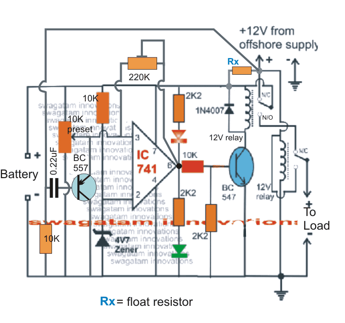
As per the above suggestion, the simple automatic battery charger can be designed using an opamp and a couple of relays as shown in the above diagram for camper, motorhome usage.
The circuit functioning can be understood as follows:
The 741 opamp is configured as a comparator, wherein its pin#3 compares the battery voltage with the reference voltage at its pin#2 which is set at a fixed potential using a zener diode network
The shore supply can be seen applied to the circuit and the battery via the N/C contacts of the relay.
The relay contacts stay connected at the N/C position during the charging period of the battery, and switches to the N/O position as soon as the full battery charge level is reached.
The Rx resistor is the float resistor which is always connected with the battery and the moment the relay contacts switch from N/C to N/O this resistor becomes active and enables the battery to switch at the float charge mode.
The second relay plays an important and in fact becomes responsible for executing the changeover function between the shore power and the battery power.
While the shore supply is ON and the battery is charging, the lower relay stays activated through the shore supply and powers the load through the same supply, however as soon as the shore supply is removed for whatever reason, the lower relay quickly changes over to its other other pair of contacts connecting the load with the N/O of the upper relay.
The upper relay contact position switches at the N/O point only when the battery is fully charged and is cut-off by the opamp pin#6 high logic response. Once this happens the contacts lock-on into this position due to the presence of the 220K hysteresis resistor across pin#6 and pin#3.
This resistor enables the relay to latch ON once triggered at the full charge situation and release when the battery voltage drops to some lower threshold, this lower threshold voltage at which the relay is supposed to restore supply back to the battery is determined by the value of the hysteresis resistor....higher values provide shorter gaps between the full charge and low charge triggering, and lower values provide bigger gaps between the full charge and the lower charge level triggering of the relay (upper relay).
The BC557 is positioned for resetting the opamp latch in situations where the battery may not be fully charged rather only partially charged.
This ensures that even if the battery is charged intermediately it connects with the load at drastic times when the shore power is removed, otherwise the opamp latch would keep the upper relay in the N/C position and fail to connect the battery supply with the N/C of the lower relay.
If you have any doubts regarding this camper or motorhome battery charger circuit, you can feel free jot in your comment below....


Need Help? Please Leave a Comment! We value your input—Kindly keep it relevant to the above topic!