In this post, I will show how to construct a over discharge protection circuit for 12v battery using Arduino which can protect 12V SLA battery against over discharge, and also protect the connected load from over voltage in case of overcharged battery is connected.
Understanding Battery Charge/Discharge Rates
All the batteries have natural decline, but most of them get damaged due to ignorance from the users part. The life span of battery will get shorten if the voltage of a battery goes below certain degree, in case of 12V SLA battery, it must not go below 11.80 V.
This project could be accomplished with comparators, but here we are using microcontroller and coding to accomplish the same.
This circuit is well suitable for resistive loads and other loads which don’t generate noise in the supply during operation. Try to avoid inductive loads such as brushed DC motors.
Microcontrollers are sensitive to noise and this setup may read error voltage values in such case, and it may cut-off the battery from load at wrong voltage.
How it Works
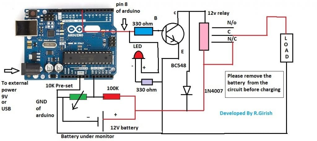
The discussed over discharge protection circuit for 12v battery consists of a voltage divider which is responsible for stepping down the input voltage and reduce to narrow range where arduino can read the voltage.
The 10k pre-set resistor is used to calibrate the readings on arduino; these readings are used by arduino to trigger the relay, the calibration of this setup will be discussed later part of the article.
A LED indicator is utilized for indicating the status of the relay. The transistor drives the relay on/off and a diode is connected across the relay for arresting high voltage spike generated from relay, while switching it on/off.
When the battery voltage goes below 11.80V, the relay gets turned on and disconnects the battery from load and LED indicator also turns on, this happen same when the circuit reads overvoltage from the battery, you can set the overvoltage cut-off in the program.
When the battery goes below 11.80V, the relay disconnect the load, the relay will reconnect the load to battery only after when the battery voltage attains above nominal voltage which is set in the program.
The nominal voltage is normal operating voltage of the load. The above stated mechanism is done because; the battery voltage rise after disconnecting from load and this must not trigger the relay ON at low battery state.
The nominal voltage in the program set as 12.70 V which is full battery voltage of typical 12V SLA batteries (Full battery voltage after disconnecting from charger).
Program Code:
//---------Program developed by R.Girish----------//

float cutoff = 11.80; //Cutoff voltage

float nominal = 12.70; //Nomial Voltage

float overvoltage = 14.00; //Overvoltage

int analogInput = 0;

int out = 8;

float vout = 0.0;

float vin = 0.0;

float R1 = 100000;

float R2 = 10000;

int value = 0;

int off=13;

void setup()

{

pinMode(analogInput,INPUT);

pinMode(out,OUTPUT);

pinMode(off,OUTPUT);

digitalWrite(off,LOW);

Serial.begin(9600);

}

void loop()

{

value = analogRead(analogInput);

vout = (value * 5.0) / 1024;

vin = vout / (R2/(R1+R2));

if (vin<0.10)

{

vin=0.0;

}

if(vin<=cutoff)

{

digitalWrite(out,HIGH);

}

if(vin>=nominal && vin<=overvoltage && vin>cutoff)

{

digitalWrite(out,LOW);

}

if(vin>=overvoltage)

{

digitalWrite(out,HIGH );

delay(10000);

}

Serial.println("INPUT V= ");

Serial.println(vin);

delay(1000);

}

//---------Program developed by R.Girish----------//
Note:
float cutoff = 11.80; //Cutoff voltage
float nominal = 12.70; //Nomial Voltage
float overvoltage = 14.00; //Overvoltage
You can change the cut-off, nominal and overvoltage by changing the above values.
It is recommended not modify these values unless you are working with different battery voltage.
How to calibrate:
The calibration for this battery over discharge protection circuit must be done carefully; you need a variable power supply, a good multimeter and a screw driver for adjusting the pre-set resistor.
1) The completed setup is connected to variable power supply without load.
2) Set the 13 volt on the variable power supply, verify this using multimeter.
3) Open the serial monitor and rotate the 10k preset resistor clock or counter clock wise and bring the readings close to the readings of multimeter.
4) Now, reduce the voltage of variable power supply to 12V, the multimeter and serial monitor must read same or very close value.
5) Now, reduce the voltage to 11.80 V the relay must trigger on and LED must light up.
6) Now, increase the voltage to 14.00V the relay must trigger on and LED light up.
7) If the above sets are successful replace the variable power supply with a fully charged battery, the readings on serial monitor and multimeter must be same or very close to same.
8) Now connect the load, the readings on both must remain same and synchronized.
If the above steps are successful your circuit is ready to serve the battery.
NOTE:
Please note this point while calibrating.
When the relay is triggered on due to low voltage cut-off or due over voltage cut-off, the readings on serial monitor will not read the correct voltage as on multimeter, and shows higher or lower than on multimeter.
But, when the voltage falls back to normal operating voltage the relay will turns off and starts showing correct voltage.
The conclusion of the above point is that, when the relay is trigged ON, the readings on the serial monitor show some significant variation and you need not to calibrate again at this stage.


Questions & Answers
i have lithium ion battery pack (nominal 14.8v, with cut off voltage 12v)
can i used the same circuit with same componet values to protect my pack from under voltage at discharge?
Yes you can use the same circuit
I have a fun challenge. I assemble portable power packs for charging personal electric vehicles(EV) like skateboards and onewheels. I use lithium ion 7s4p battery packs built with a boost converter to boost the 29.4v power to up to 63v for the charge. The boost converter has 3 circuits for output voltage, current limiting, and supply low voltage cutoff.
I am trying to figure out a method to allow the charge to be initiated with a time delay to eliminate the spark when plugging into the EV and voltage check from the EV to initiate the timer. Once charge current drops to .5amps auto shut off. I would like to be able to have the ability to adjust the input start voltage to meet the low voltage from the battery being charged. This would be to replace a manual on/off switch that a user must engage to start/stop the charge cycle.
-7s4p 29.4v high and 20.8v low as source.
-Boost converter with output voltage, current limit, and low cutoff on input voltage
-Capacity indicator
The adjustable time delay feature is possible!
Boost converter is possible!
The current based auto shut off is also possible.
However, I could not understand what you exactly meant by the following statement:
“I would like to be able to have the ability to adjust the input start voltage to meet the low voltage from the battery being charged…”
The input voltage is supposed to be constant regardless of the low voltage level of the battery, according to me.
Nice work you are doing.
I tried the circuit the voltage value is not stable the relay is just switching off and on what might be the cause
It can be difficult to troubleshoot the fault without seeing your circuit practically, and without a detailed information about the fault.
Pls I guess this circuit required two relays one for fully charge and one for low battery.
yes, it is only for over discharge protection, the over charge protection will required additional upgrade
Hi. What is the purpose of the 10k Potentiometer in this diagram?
Battery 18650 Li-ION
3.7 V 2200mA , upto 4.2 V
discharge @2AH
Cut-off required 2.8V or battery temp >55 degree
for this battery I need cut off voltage setable with preset and also need temperature protection .
Load on this battery is small pump .
can you design for it ,please reply at email
You can build the first circuit from this article;
https://www.homemade-circuits.com/li-ion-battery-charger-circuit-using-ic/
Hiya
I am trying to use your circuit for an electronic project in college in Electronic Engineering. Would many changes need to be made if a PIC were used instead of an Arduino?
Hi, Sorry I have no idea about the question you have asked, however, since Arduino also uses a PIC, it might be possible to do that!
i copy the above code for battery protection and paste it into arduino sketch when i upload it….an erro appear at the end below saying…
void
exit status 1
“stray ‘ \342’ in program
it can’t upload…
I confirmed it in my Arduino IDE, it compiled perfectly, please check your IDE, may be there’s something missing in it.
Can the load be the arduino project including the arduino itself?
No, because Arduino takes times to boot and may cause the circuit to behave erratically.
Need some leads about how to do the same.
I want to recharge the batteries for the arduino and the rest of the project without using one extra arduino. Also need to sense the bat levels and a overcharge cutoff circuit.
I don’t think you can have two programs in one Arduino
I want a standalone battery operated project and when the battery is charged it should not power the load and the charger should power the load and charge the battery in parallel.
Do you think a tp4506 with load sharing circuit should do my purpose?
You can use any battery charger for load sharing as long as the charger is rated to provide the required amount of current for the battery as well as the load.
Sir this circuit only 9v 12 battery charging enogh 9v ? And can you make with LCD for monitoring
Aslam, this circuit is an over discharge protector for the battery and over voltage protector for the load….it will not charge the battery. Moreover the 9V is only for the Arduino.
How can I control the battery charging and discharging automatically when it reaches determined low and high voltage while charging?
also the current rating is 100A (100A load can be connected for discharging)
battery output max is 100V.
CAN YOU PLEASE HELP ME TO SOLVE THIS PROBLEM??????
I explained many battery charger circuit in this website, you can select any one of them appropriately and use it for the purpose.
For 100V you can apply the following circuit:
https://www.homemade-circuits.com/high-voltage-360v-battery-charger/
Hii sir,
https://www.homemade-circuits.com/make-this-48v-automatic-battery-charger/
The ckt diagram in above link can satisfy the charging discharging of four 12V,12AH batteries in series means is it suitable for 48V. operation.?
# Upto 42V the battery should be discharge
# Two loads connected in parallel for discharging first is heavy load and 2nd is light load & switching should be happen after voltage dropped to 42V.
ok sir, you have to only tell me the Rating of mosfet and the green diode used near the mosfet please tell this so that I can start my project…..please help
Naman, MOSFET is IRF540, and green diode can be a green led or a red led. Please note that the first 3 diagrams do not have automatic low voltage detection and re-charging facility, it will only cut off when battery reaches full charge level, and MOSFET will shut off permanently until power is switched OFF and ON again..
Thankuhh sir I must try it….can you please tell me details of all equipments used in the ckt. because in some diodes full details are not mention I have to buy all the things used in this ckt.
please share bills of materials so that I am able to do it………and thanks again for your support .
I’ll try to do it soon…
Hi Naman, yes you can use the diagrams for your battery, but make sure you always use the batteries in series only, never use them separately otherwise they may get affected with differing charging characteristics.
If possible I’ll try to update an improved design using lm393 iC which is a better comparator than IC 741
i just watch your circuit about Li-ion Emergency Light Circuit with Over charge and Low Battery Cut off Features. is it related to my desired circuit like i mention above? or it just for overcharge protection?
No it's not as per your requirement. The first circuit from the following link might satisfy your requirement.
https://www.homemade-circuits.com/2012/07/make-6v-4ah-automatic-battery-charger.html
can you give me a circuit to auto on and off cell phone charger. Detail is:
1. the charger will charge the phone and it will stop charging when 100% full(overcharge protection)
2 the charger will start charging again if the user didn't unplug the charger from the phone. it will start charging again when the battery shows only 20% capacity in phone screen
Li-ion can also be charged with the above circuit, just make sure the input current is as per the rating of the batt
this circuit can it be done with 3.7v battery? which component that i need to change?
All cellphones have an in-built overcharge cut off and a low charge restart, so an external circuit is never required. Even if the charger remains connected permanently the internal cut-off circuitry of the phone will keep the battery safely charged.
By the way Li-Ion batts should be never discharged to 20%….