In this post I have explained a circuit configuration which facilitates a multi-step low voltage selection and cut-off for the battery being used and monitored. The circuit was proposed by Mr. Pete.
Technical Specifications
Dear Swagatam,
Your assistance during the past few days has been incredible, thanks to which I think I have managed to get close to this 4 step low battery cut off circuit I need.
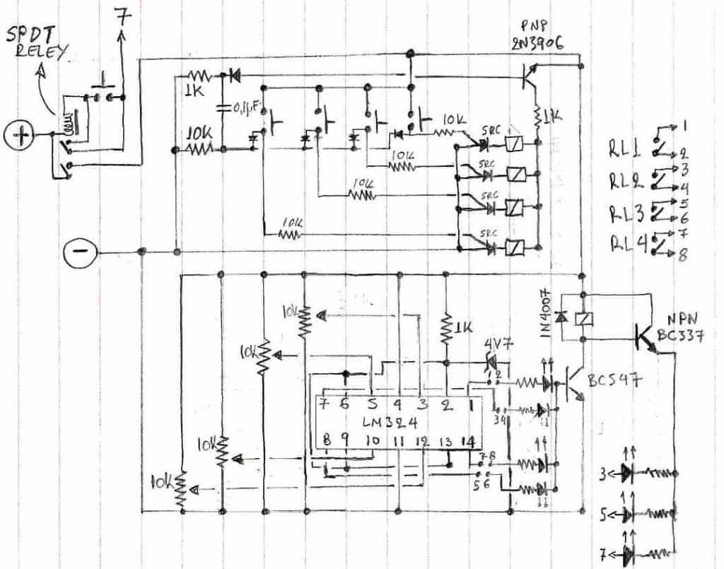
Having combined your info, a selector circuit I found in a different source and by adding my own ideas I came up with the following circuit:
I know there are issues which with my knowledge I cannot solve, but I think I am close (I will list these issues at the end of this post).
My knowledge is limited (I am neither an expert nor a novice in electronics), so I would like to hear your opinion and recommendations.
To my understanding, what I expect it to do is as follows:
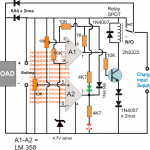
LM324 will monitor the voltage and turn off the relay at the bottom of four scales: 18.5-20V, 20-22V, 22-24V, 24-28V adjusted by the various 10K presets.
The circuit starts (battery full) with the relay armed (load connected) and the 24-28V LED on (left hand side set of LEDs).
The selector circuit (top part) assures that only the selected OPAMP arms the relay although all of the OPAMP outputs will be high at the same time (this I need for a later function, see end of next paragraph).
During discharge, when 24V is reached the equivalent output (1) will go low and the relay will disarm, disconnecting the load. At the same time BC337 (NPN) will conduct and light up the three right hand side LEDs, to indicate scale options that are available.
Once a button on the selector is pressed for a lower scale (i.e 22-24V), the relay at the lower circuit will arm by the second OPAMP (output 7) and the load will be connected. Same goes for the equivalent left hand side LED. The same applies for the 20-22V scale, but only 2 LEDs will light from the right hand side set).
Now, if the last scale (18-20V) is selected, when 18V is reached the 4th OPAMP of the LM324 will disconnect the load once again but at the same time the SPDT relay at the top left of my picture which is connected as a latching relay will disarm and take power completely off of the circuit to minimize consumption as the battery will be very deeply discharged now.
In order to start the system again, manual reset will be required via the push button near the latching relay, once the battery is charged again.
The purpose of this circuit is for a solar system used to power an emergency communications station. This is the reason it cannot be set in a completely automatic way.
Although deep discharging of the batteries is not recommended, in such stations the operator will have to judge whether he must deep discharge the battery or not, in case the type of emergency makes it inevitable.
Under normal situations, the power will cut off at 24V automatically protecting the batteries, but it is important that the operator will have the option to continue drowning the batteries if necessary.
So here are my circuit issues:
1. I have a fear that in the way the circuit works, the outputs go high, not low when thresholds are met. If it is so the circuit will not operate in the intended way, especially the latch relay function.
2. I have a feeling that there will be a lot of small and big flaws in my additions to the design. I am confident in building it when it is all designed, but designing of circuits is a skill I only have to certain extend.
3. I wonder if I can substitute the relays of the top part of the circuit with some kind of low power MOSFET. If so, please give me a clue as to how to connect them.
4. I am also thinking that the disconnection of the load will cause the system to do some chasing effect, so I wonder if some small hysteresis can be added.
Please get back to me with you thoughts; I believe this can be a useful 4 step low battery cut off circuit if ever completed for many people (maybe by adjusting the thresholds to higher values, not everybody needs to drain their batteries so much).
My gratitude once again for the tones of information you have helped me to collect during the past week.
Regards,
Pete
Simplified Diagram for the above Circuit Issue [Solved]
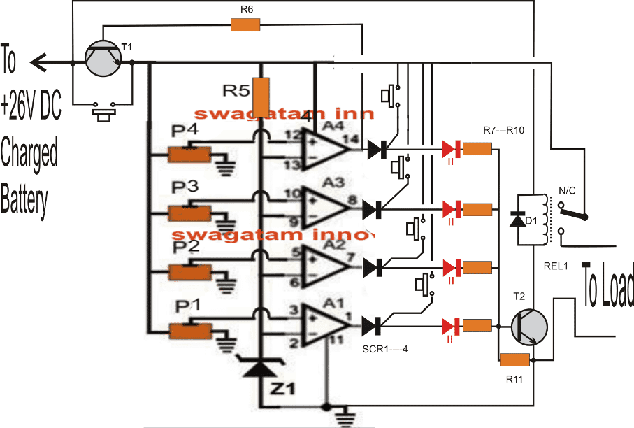
Parts List
All resistors can be 10K 1/4 watt
All presets = 10K
T1, T2 = BC547
Relay = 24V/SPDT
Scr = BT169
IC = LM324
D1 = 1N4007
Z1 = 6V/400mW

Questions & Answers
This excellent website certainly has all of the information and facts I needed about this subject and didn’t know who to ask.
Thank you, glad it helped!
can this schematic/ equipment be modified for use on a 144 vdc battery used in a Honda high bread.
I made a charger from another site but need a safe way to discharge so as to have a good balance when recharging.
michael
"…need a safe way to discharge" I did not understand this, please explain it clearly.
Thank you! I wrote the reply in that article.
-David
Hi David,
I have addressed it here:
https://www.homemade-circuits.com/2013/10/low-battery-cut-off-with-indicator.html
Thank you Pete!
I am sure your involvement and contribution would be appreciated too by the viewers.
Feel free to express your thoughts and queries as you move ahead with this project and possibly many more in the future.
technically it looks feasible, might require some practical adjustments…
you are welcome!
The 1K resistor should be removed otherwise the relays might not operate, also the relay coils would work better at the anodes of the scrs rather than at the cathodes.
The diagrams are drawn with dashed lines which is making it very difficult to follow and time consuming.
My previous suggestion can be implemented by simply adding another relay with T2 and wiring its contacts with push button common joint.
What do you think?
Thanks Pete! I appreciate your feelings!
If SCR1 is the device which needs to be triggered then it may be done as shown in your diagram, but it will need to done via a 1uF cap in series with the 5th opamp output.
The other issue, relating to the preventing of simultaneous scr triggering can probably be solved by cutting the push-button common point joint from the shown positive supply, and connecting it to the relay N/C contact. I hope you will understand the reason behind this.
cheers!