In this post I will explain one useful SCR relay battery overcharge cut off circuit, which also has automatic latching and small trickle charging feature, so now when battery becomes fully charged then charger disconnects automatically, but still a tiny current keeps going into battery slowly.
Main Features
Main interesting thing here is the SCR latch action, because relay does not keep doing ON OFF chatter near cutoff voltage, which normally happens in many simple relay charger circuits. Another great thing is the trickle charge feature which makes sure the battery is immediately switched into trickle charging mode, as soon as the full charge level is reached and auto cut-off is implemented.
Audio/Video Representation
Circuit Parts and stages
We have IC 741 here, one BT169 SCR, one relay, zener diode, some resistors and capacitors, that is mainly all the parts used.
Circuit can be seen like four small sections, one battery sensing side, one reference voltage side, then SCR relay latch side, and lastly trickle charging side.
How the Circuit Works
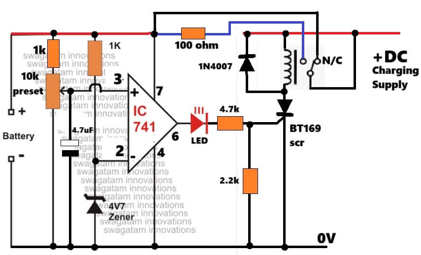
So now starting from the sensing section, the 10k preset together with two 1k resistors samples battery voltage and feeds it into pin number 3 of IC 741, which is the non-inverting input side.
Preset is adjusted for the exact full battery voltage level which we want the circuit to detect.
That 4.7uF capacitor helps calm noise a bit, otherwise relay may chatter randomly.
Pin number 2 gets fixed reference voltage from the 4V zener diode, so now op amp keeps comparing both sides continuously.
At pin 2 there is fixed reference.
At pin 3 there is battery sample voltage.
As long as battery voltage stays lower than preset level then pin 3 voltage also stays lower than pin 2, therefore output pin 6 remains low.
Since output stays low, LED remains OFF, SCR remains OFF, and relay also stays inactive.
Now see relay contact carefully, charging supply goes through the N/C contact of relay.
Since relay is OFF initially then N/C contact stays connected, so charging current reaches battery normally and charging keeps happening.
Now when battery voltage slowly rises during charging then voltage at pin 3 also rises slowly.
The moment pin 3 voltage becomes slightly higher than pin 2 reference, IC output instantly goes high.
That high output now does three things together.
LED turns ON first, which shows full charge condition.
Then high signal passes through LED and 4.7k resistor into gate of BT169 SCR, and SCR switches ON immediately.
Once SCR conducts then current starts flowing through relay coil, from positive supply through relay coil then SCR and finally ground.
So now relay energizes.
This is where the clever part comes.
Relay Latching Feature with SCR
When relay energizes, relay contact shifts away from N/C point, therefore main charging line disconnects from battery and charging stops immediately.
But relay contact arrangement also keeps supplying power to relay coil after switching, so now even if op amp output fluctuates slightly afterward then SCR and relay still remain latched ON.
That is very important because relay chattering near cutoff voltage gets stopped.
Relay stays locked like that until charging supply is removed manually.
Trickle Charging Feature
Now coming to the trickle charging side, even after main charging path disconnects, battery is not completely separated from charger.
One 100 ohm resistor still remains connected between charger positive and battery positive, therefore a very small current keeps flowing into battery continuously.
That small current works like trickle charging and helps compensate battery self discharge.
Since resistor value is fairly high, current stays small and safe.
For example if charger voltage is 15V and battery voltage is 14V then current becomes roughly around 10mA.
Now we see the diode connected across relay coil.
That 1N4007 diode acts like flyback protection diode.
Whenever relay switches OFF then relay coil produces reverse voltage spike, so diode absorbs it and protects SCR, IC and LED from damage.
One big advantage of this circuit is the SCR latch system, because cutoff becomes stable and relay does not oscillate near threshold voltage like ordinary relay cut off circuits.
Important Note
One practical point also here, IC 741 was originally designed for dual supply operation, therefore modern op amps like LM358 or LM393 work much better on single supply 12V battery systems.
These ICs give more reliable switching performance.
Still the old 741 version can also work reasonably well for basic battery charger applications.


Need Help? Please Leave a Comment! We value your input—Kindly keep it relevant to the above topic!