In this post I have explained how to recharge and use bad, defective discarded batteries using an innovative battery charging process invented by John Bedini.
Lead acid batteries can sometimes be a problem to get rid of. They can also be high priced to upgrade. In case discarded in the wrong way, they have a tendency to finish up in the land fill up or even rotting of in your junkyard.
Contribution of John Bedini
John Bedini has presented a bequest to the world which can bring back and enrich the used, abandoned, sulfated batteries.
In case your battery is sulfated from typical utilization, it may commonly be recovered using this discovery.
Batteries which have material impairment or have warped plates are worthless. The Bedini SSG (Simplified School Girl) generator can separate the sulfation on the battery plates and energize the batteries. On many occasions, the battery will in fact acquire further voltage, workable power compared to the time it had been purchased.
By means of routine utilization, a battery would probably gradually drop its potential to hold electricity. This can be witnessed by the necessity to charge the battery far sooner every time. Typical battery chargers often give rise to this consequence due to heating effect of the battery.
Because the plates get hot by way of charging, these are steadily weakened. A battery may have less electrical power every time it is utilized.
With the Bedini charger, that is not the situation. I have reconditioned batteries which were found resting around in a trash.
A couple of such batteries that possessed a charge of below 2 volts each presently are running my electric boat generator.
These types of batteries were not consuming a charge with regular chargers. After a while and many rounds with the Bedini charger, the batteries have become superior to brand new.
How Bedini SSG Function
This electric motor would not self start. You need to provide it with a little bit force to pick it up going, however once it begins rotating it is going to turn up by itself and self adjust its very own acceleration and speed depending on the dimensions and charge condition of the batteries getting charged.
Since a magnet moves down the coil, a tiny electric current is stimulated into the main coil.
This activates the transistor to switch on, enabling electricity from the operated battery to stream by way of the supplementary coil.
The magnetic field generated in the secondary coil provides the cycle a tiny lift up on its path past the coil.
As the magnetic field sets off the coil, the transistor is turned back off. This leads to the magnetic field in the supplementary coil to drop (back emf).
During this period, the vibrant electric power makes its way into the process which is emptied via a diode into the batteries to be charged.
This method could be demonstrated to generate additional energy on the recharging aspect compared to the need to steer the motor. In the method presented, the input current amounts between 150-200 mA.
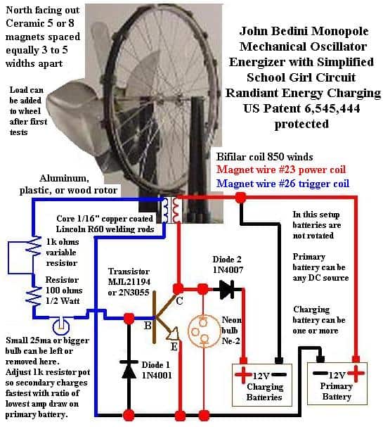
John Bedini Monopole Mechanical Oscillator Energizer with Simplified School Girl Circuit Overview
This diagram is showing the full circuit setup of John Bedini Monopole Mechanical Oscillator Energizer, which is popular as Bedini SSG or Simplified School Girl circuit.
This arrangement is mainly designed for radiant energy battery charging system and it comes under US Patent 6,545,444 protection.
The entire setup is combining one mechanical rotor wheel with magnets and one electromagnetic circuit having bifilar coil, transistor switching mechanism and two separate battery sets.
Rotor and Magnet Assembly
At top side of this setup, one well balanced wheel is mounted which is working as rotor. The rotor wheel can be made using non-magnetic materials like aluminum, plastic or wood so that magnetic interference will not happen.
On the outer rim of wheel, ceramic grade 5 or grade 8 magnets are fixed properly.
All magnets must be placed keeping North pole facing outward only. The gap between each magnet should be kept equal, around 3 to 5 magnet widths distance apart.
If you want to add some mechanical load on wheel, you can attach it after finishing initial testing process.
Bifilar Coil and Core Details
Just below rotor wheel, electromagnetic coil assembly is placed which interacts whenever magnets pass over it.
Center core of coil is constructed using 1/16 inch copper coated Lincoln R60 welding rods cut into equal length pieces.
Coil is wound using bifilar method with total 850 turns. It is having two separate magnet wires wound together at same time.
First one is gauge 23 magnet wire used as power coil, shown with red color path in diagram.
Second one is gauge 26 magnet wire used as trigger coil, shown with blue color path in diagram.
Trigger Circuitry and Adjustment Settings
Trigger circuit is catching magnetic pulse from rotating wheel and switching transistor ON and OFF automatically.
One side of gauge 26 trigger coil is going directly to base terminal of transistor.
Moving along blue line path, signal goes through 1k ohm variable resistor potentiometer and 100 ohm 1/2 watt fixed resistor connected in series.
One small bulb of 25mA capacity or bigger is connected in series along trigger line. You can keep this bulb for checking trigger current visually or remove it later after full setup.
One 1N4001 diode named Diode 1 is connected between base terminal and common ground wire coming from emitter.
By adjusting 1k potentiometer knob, you have to tune circuit in such way that secondary output battery is charging at maximum speed while primary input battery is drawing minimum possible current.
Power Circuitry and Transistor Hookup
Main power switching part handles high voltage radiant energy spikes created when coil magnetic field collapses.
Transistor used here is MJL21194 or standard 2N3055 power transistor.
Base terminal receives trigger signal from blue path. Emitter terminal connects directly to common ground wire going to negative side of Primary Battery.
Collector terminal is attached to output end of gauge 23 red power coil. One Ne-2 neon bulb is wired across collector and emitter terminals.
This neon bulb acts like safety feature to bypass high voltage voltage inductive spikes if output charging battery gets accidentally disconnected during running condition.
Battery Connections and Output Wiring
Circuit uses two separate battery banks so input power side remains fully separated from output charging side. In this basic layout, batteries are not swapped or rotated automatically. Primary source can be any fixed DC power supply or 12V DC battery.
Positive terminal of Primary Battery connects straight to input side of red power coil.
Negative terminal connects to ground rail joining emitter and Diode 1. On output side, one or more 12V batteries can be connected in parallel for charging.
High energy flyback pulses leave collector terminal, pass through 1N4007 diode named Diode 2, and connect to positive terminal of Charging Battery.
Negative terminal of Charging Battery is connected back directly to positive terminal of Primary Battery.




Questions & Answers
Hi. Good day Sir.In the Bendini circuit ,the positive line is connected to the charging battery. Is this correct .
Good Morning Raj,
The positive of the charging battery is connected to the BJT collector via a diode, and its negative is connected to the positive of the primary battery….
hi sir, good day. i have replicated this device and charges well, especially those old ones. can you design a battery swapper or a simple cap dump circuit implementing a comparator circuit. thank you
Hi Alinader,
I have a related concept in this blog, which can be modified for your application, you can read it here:
https://www.homemade-circuits.com/multiple-battery-charger-using-dump-capacitor/
Kako da napravim strujno kolo 12, 24, 36, 48 V DC struje da menjam voltažu i da menjam frekfenciju od 500 KHz. Za elektrolizu vode.
Kako da upotrebim struju iz bobine za elektrolizu vode.
Hi Swagatam,
Can you demonstrate how to make the coil/s using R60 copper coated Lincoln rods. How to make them or I mean how many R60 rods will be used, and its physical appearance after made as a “core” before winding the 850 turns magnet wires on both windings?
Sorry Egay, I do not have the required information regarding how to make R60 copper coated Lincoln rods
How the PH and TDS value of Distilled water affect the Battery life. Can any one explain in detail, with chemical formula.
If the water has been distilled the TDS will be 0. Pure water is also neutral so the Ph should be 7.
Hi Sir,
Do you happen to have a battery swapper circuit which can be implemented in this Bedini circuit diagram. I have seen your "Twin or Split Battery Charger Circuit ' (https://www.homemade-circuits.com/2014/05/twin-or-split-battery-charger-circuit.html). Can this be integrated with the Bedini circuit diagram . If YES, what modification should be done on this circuit .The aim is to let the motor run without having to physically stop and swap the battery , making it almost overunity unit.
Many thanks in advanced.
….moreover the primary battery never gets discharged according to the theory
Hi Naser,
both the batteries are differently rated so cannot be swapped….the primary battery is any used, discarded, sulphated low AH battery while the other one is a good battery….I don't think swapping the batteries is recommended in the design.