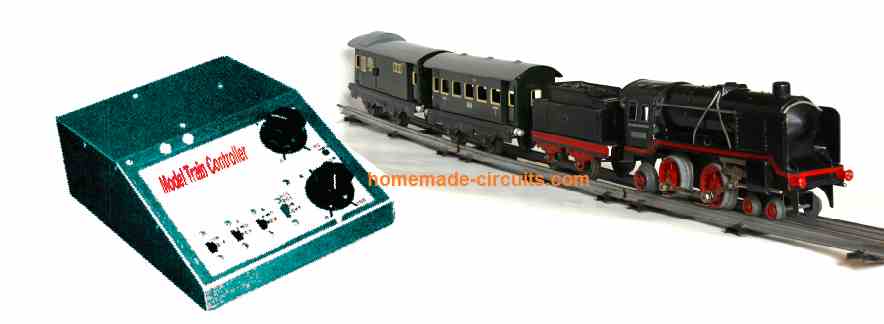
In this post I have explained how to build a simple yet a realistic model train controller circuit, which can be integrated with the rail tracks of an existing motorized train system and used for controlling its speed, acceleration, deceleration with original effects.
How the Circuit Works
A schematic diagram for the Train Controller can be witnessed Fig. 1 below. As demonstrated, a 555 timer (U1) is set up for an astable multivibrator (oscillator) having a duty cycle of 400:1 duty cycle and also a frequency of 40 Hz.
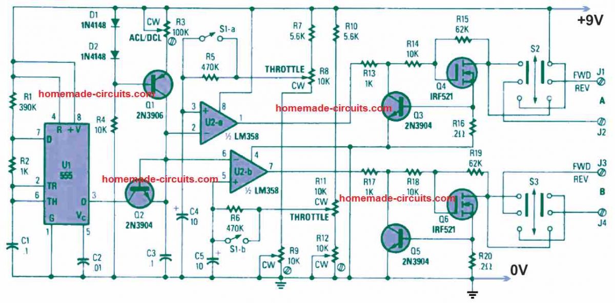
This frequency reduces flickering of the train headlight but yet makes it possible for the motor armature to get pulsed so that it is able to change over gradually for crawling and slow-speed control. As soon as power is given to the circuit, it discharges the capacitor C1 which can be seen connected to pin 6 of U1. The IC 555 output which is utilized to shunt current is held low. Capacitor C1 starts charging by means of R1 and R2 and gradually moves towards the positive supply level.
As soon as the charge across the C1 extends to around 2/3rd of the positive supply, the U1 555 output at pin 3 becomes high.
At this juncture C1 starts to discharge via R2. The moment the charge inside C1 drops to approximately 1/3rd of the supply voltage, the U1 555 output comes back to the low logic condition, and this high/low changeover cycle goes on repeating as long as power remains connected to the circuit.
When the U1 555 output goes low, C3 gets discharged via U1 pin3 transistor Q2. Next, as soon as U1 pin 3 turns high, C3 now charges by means of a current source which involves diodes D1, D2, resistors R3, R4, and transistor Q1.
The repetition of charge/discharge across the capacitor C3 causes the generation of a string of pulses which are applied to the inverting inputs of U2a and U2b which are the op amps from the IC LM358 dual op amp.
A couple of resistive potential divider circuits including resistors R7, R8, and R9, and resistors R10, R11, R12 establish the reference voltage which is given to the non-inverting pin3 and pin5 inputs of U1a and U1b. Variable resistors or pot controls R9 and R12 are used for adjusting the low DC duty cycle between 5 to 10 % of U1a and U1b.
The pots are adjusted to ensure that the headlights of the train illuminate optimally but with minimal humming noise on the train motors. Potentiometer R3 is used for setting up the C3 ramp rate for 100% duty cycle when the throttle adjust is set to maximum. A DPST switch (S1a snd S1b) is incorporated to include R3/C4 and R4/C5 into the circuit.
The network comprising of resistors and capacitors R5/C4 and R6/C5 force the reference voltages introduced to the non-inverting inputs to U2a and U2b to switch extremely slowly whenever the throttle is flipped upward and moved downward. Due to this action the train movement behaves as if it is making an attempt to counter a high level of inertia while it is just starting or stopping.
When the ACL/DCL button is switched off, the throttle-divider resistance networks tend to be a lot lesser compared to those of R5 and R6, therefore the reference voltages applied on C4, C5 adjust "quickly" for the fresh throttle setting. This allows steering clear of possible accidents or derailments while operating the model trains.
The model train output motor controllers incorporate resistors R13 to R15, and transistors Q3 and Q4 for energizing output "A;" and resistors R17 to R20, and transistors Q5 and Q6, for energizing output "B."
The parts that includes R13/R16/Q3 and R17/R20/ Q5 are configured to limit the Q4 and Q6 output drive currents to around three amperes each. Resistors R14/R15 and R18/R19 are used fir biasing and switching Q4 and Q5, respectively, just before the over voltage is reached to stop any harm to the output driver transistors and also neutralize the back EMF transients released from the inductive motor loads.
Power Supply
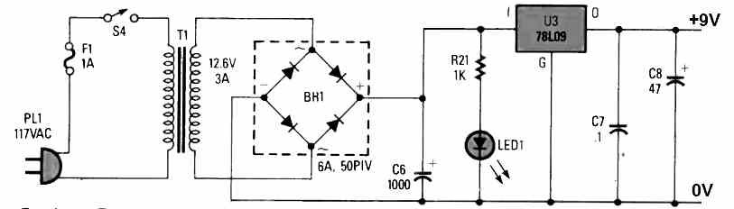
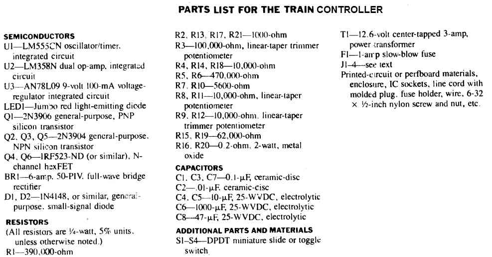
The power supply is configured to provide 18 volts to the model railway tracks, which is obtained from the points across C6. The voltage regulator U3 which is a IC 78L09 9 volt, 100 mA voltage regulator, is configured to provide the required regulated 9 V power to the control circuits, comprising of the op amps, transistors etc..
Construction
The author's model train controller circuit had been initially put together over a section of perfboard or strip board. A neat little PCB layout was subsequently developed for the proposed Train Controller circuit. The complete PCB layout (along with specified measurements) can be witnessed in Fig. 3 below.
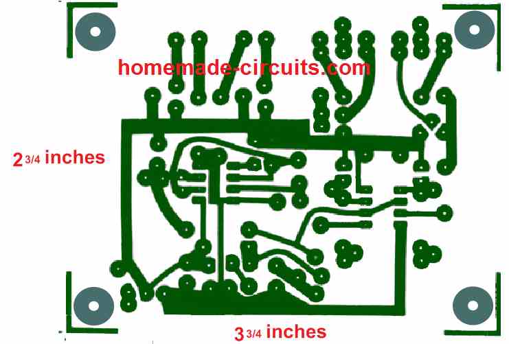
It is possible to do the etching work of your own board or make to order from one of the relevant online suppliers. Once the PCB is obtained, it is just about fitting all the parts on the board and test the unit by doing the necessary connections with the railway tracks.
J1---J4 can be any suitable connectors, such as speaker connectors, which can be used for hooking up wires across train controller and the railway tracks.
Parts List
How to Add a Soft Delayed Acceleration and Braking to any Model Train Controller
The following idea of a delayed acceleration and braking effect was requested by an avid reader of this blog, Mr. Rocco. Here's what exactly he wanted to implement for his model train controller setup:
I’d like to build a simple power supply for electric trains, for example using the basic circuit with an LM317. In this case, the minimum output will be 1.25, so I thought I’d add two diodes to the output to reduce it to zero.
My question is that in addition to the potentiometer that regulates the output voltage, I’d like two more, one to delay acceleration and the other braking.
Can you help me?What do you think of the LM317 as a power supply for electric trains? Or can I use something different?
Why LM317 Is Not Good for Electric Trains
Actually the LM317 cannot go down to 0V. Its lowest output is 1.25V. of course you can add two diodes at the output to drop that voltage down to 0V so the train can stop. But adding acceleration and braking delay knobs to an LM317 is very hard because its pins pull current and mess up the delay timing. Also linear regulators like the LM317 waste a lot of power as heat when the train runs slowly, causing the motor to lose power and stop working easily.
A Simple and Better Idea: PWM with Delays
Instead of using an LM317, it is much better to divide the circuit into two simple parts:
- A small delay circuit using a capacitor to make speed change slowly.
- A 555 timer PWM circuit to run the motor smoothly without making heat.
By using two simple diodes, we can charge and discharge the capacitor through two separate paths. This gives you one knob for acceleration delay and one knob for braking delay.
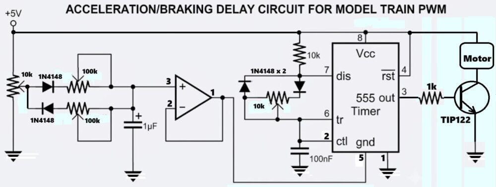
How the Circuit Works Step-by-Step
1. Main Speed Knob and Diodes A 10k speed knob gives a voltage from 0V to 5V. Two small 1N4148 diodes split this voltage into two different paths.
2. Acceleration and Braking Paths
- Acceleration Path: When you turn the speed knob up, then current goes through the top diode to charge a 1µF capacitor slowly. This makes the train speed up slowly like a real heavy train.
- Braking Path: When you turn the speed knob down, then current flows back out through the bottom diode to empty the capacitor slowly. This makes the train slow down gradually to a complete stop.
3. LM358 Op-Amp Buffer The voltage on the 1µF capacitor goes into an LM358 op-amp buffer. This buffer protects the capacitor voltage so the rest of the circuit does not drain it too fast.
4. 555 Timer PWM Output The output from the LM358 connects to Pin 5 of a 555 timer chip. The 555 timer turns this smooth voltage into fast ON/OFF pulses for the motor. This gives the train full motor power even at very slow speeds.
How to Use the Controller
- Setup: Turn the main speed knob to maximum. Then adjust the small 10k trimmer on the 555 timer until the train reaches a good top speed without motor noise.
- Set Delays: Adjust the acceleration knob for how fast the train speeds up, then adjust the braking knob for how long it takes to coast to a stop.
- Run the Train: Set the main speed knob to any speed you want. The circuit will automatically speed up the train slowly, keep it running smoothly, and brake it gently when you lower the knob.
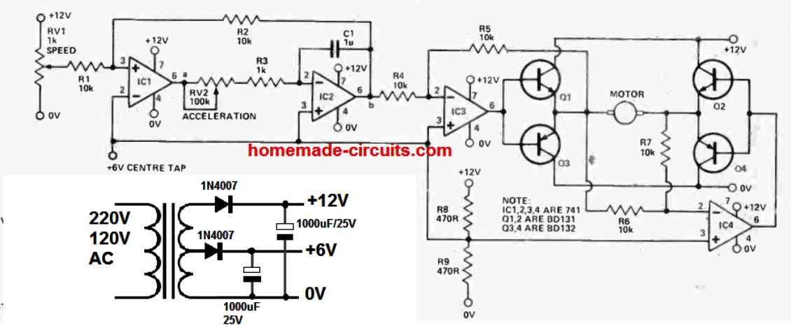
Another Simple Model Railway Controller Circuit
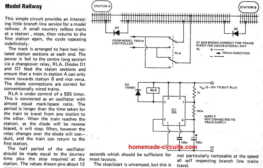
Model Train with Soft Start


Questions & Answers
If I credit you and link your article can I build the controller and write an article about it on my page ?
Yes, you can.
I just finished drawing a PCB and a Gerber file. I added an LM317 to regulated the incoming voltage so you can power the board with wallwarts from 12v to 24v.
Sounds great, all the best to you.
Hi do you have a PCB layout for the components ? that would be appreciated!
I just drew a PCB and the Gerber files.
Hi, Sorry, I do not have the PCB component layout for the above project.
Thanks for these great schematics.
On the first one, Q2 has its emitter connected to its base. Is this on purpose? I think it will act as a diode, not as a transistor, right?
Do you have the other side of the PCB so we know where each component goes?
You are right, it seems Q2 is configured to work like a diode.
Sorry, I do not have the other side of the PCB layout.