In this post I have explained a simple automatic High Voltage Battery Charger Circuit which can be used for an automatic charging control of any preferred high voltage battery bank such as a 360V battery bank. The idea was requested by "resonance".
Circuit Objectives and Requirements
- I found all your circuit and projects interesting but please I need a special assistance.
- I want to build a Low and high battery full cutoff that can handle about 360VDC (30 Batteries in series) such that when battery is full at 405VDC charging Voltage will cutoff and when battery drop to like 325VDC it also cutoff battery low.
- Please, do share this experience with me.
Circuit Diagram
The Design
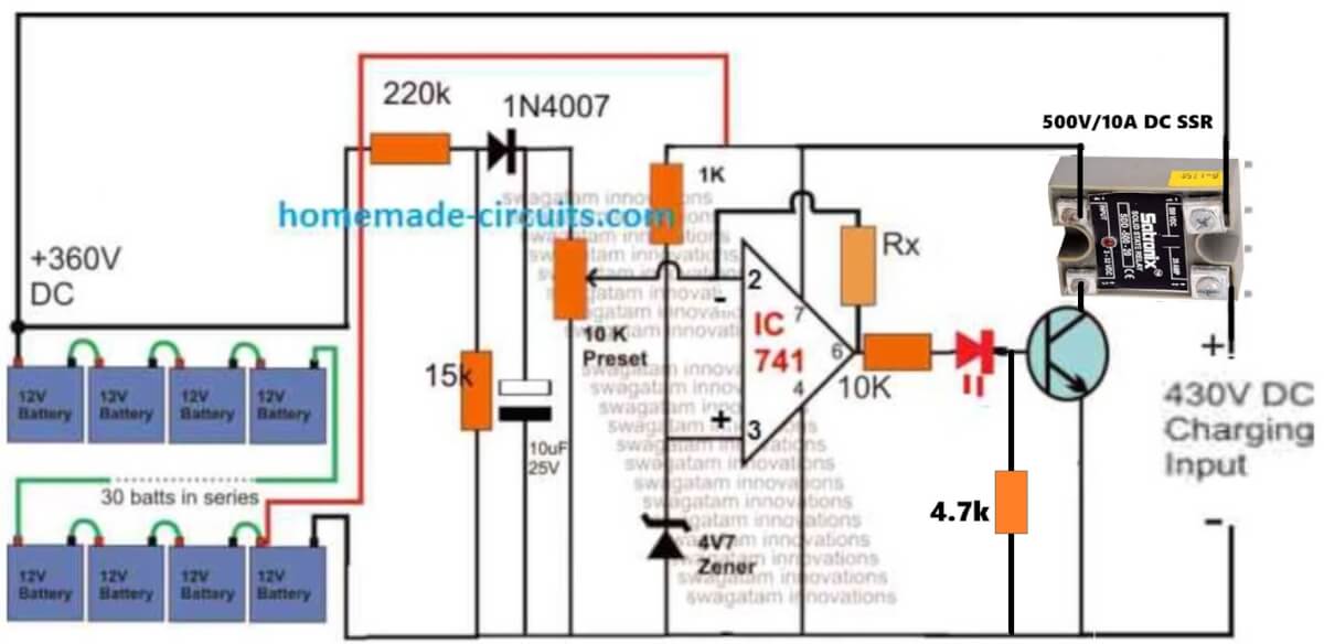
The figure above shows a straightforward configuration for achieving the proposed automatic high voltage battery charger circuit in the order of 360V.
The idea is based on the standard opamp based comparator principle, which is also implemented in many of the earlier 741 based battery charger circuits.
The circuit functionality can be understood as I have explained below:
The 360V is achieved by adding 30 nos of 12V batteries in series, which constitutes 430V level as the full charge threshold, and 330V as the full discharge level threshold.
The battery bank voltage needs to be controlled within these limits for ensuring a safe charging environment for the batteries.
The opamp circuit is configured for implementing the above mentioned high voltage charging control as indicated in the diagram.
The 360 V is stepped down to a suitable proportional level for the opamp sensing input at its inverting pin#2 applied via a 10 k preset. This is done through a potential divider network using a 220 k and a 15 k resistor.
The non-inverting pinout of the opamp is clamped at 4.7 V through a zener diode for providing a reference to its complementing pin#3 sensing input.
The operating supply voltage for the opamp pin#7 is extracted from one of the batteries associated with the negative line of the system.
Preset Adjustment
The preset is adjusted such that the opamp output pin#6 just becomes high and triggers the transistor when the battery voltage reaches at around 430V.
The above action forces the SSR to operate and cuts off the supply charging voltage to the battery bank.
As soon as this happens, the battery voltage tends to go down a bit which normally prompts the opamp to trigger back the SSR ON, however the presence of the feed back resistor connected across pin#6 and pin#3 holds the opamp situation, and prevents this from happening.
This is also called the hysteresis resistor which temporarily latches the opamp to a certain voltage range depending on the value of this resistor (Rx).
Here it must be selected such that the opamp stays latched until the voltage of the battery bank drops to about 330V, after which the opamp could be expected to restore the SSR back in its ON position initiating the charging process for the batteries.

Questions & Answers
hi, swagt, you are the right person i have ev scooter, battery 60v 23amp, it has 71.5vdc 3amp charger, i am turning to transformer based charger, which is better since my smps based is has blow 3 times, so i need a variable high and low cut off of 60v -72v, pls can you help? normal module available only can adjust till 60vdc …..in advance.. thank you
Hi John,
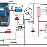
you can try the following circuit, let me know if you have any issues with the implementations:
Hi swagatam sir, I need variable auto cut off circuit for charging different lithium & lead acid batteries. ex:- 12v – 100v & 20-100amp batteries. . can I use this circuit. Please clear that is this ok for that or any changes I have to do.
-This circuit works on which min. & max. voltages & charging amp support? ?
-What will be the relay configuration for max 20 amp charging current?
-Can I use variable resistor in Rx place?
-Any Zener diode modification?
Hi Subroto,
The above circuit will need many modifications to charge batteries from 12V to 100V.
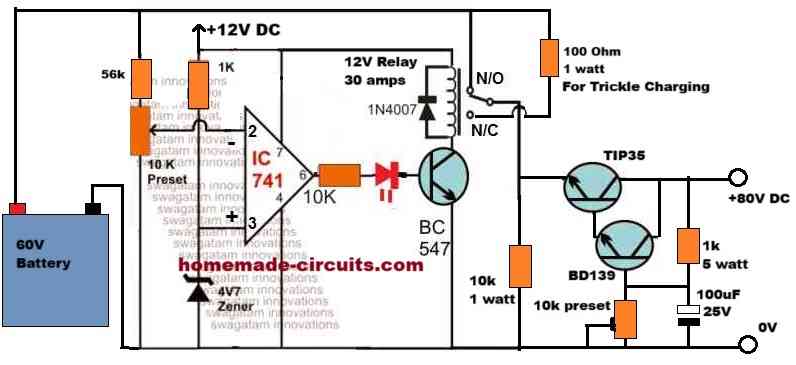
Instead I would recommend trying the last circuit from the following article:
https://www.homemade-circuits.com/make-this-48v-automatic-battery-charger/
Hello sir, a/c ur recommendation 48v last circuit if I use, what voltage range of lithium batteries will work on that circuit. Means for 48v, 60v ,72v , atleast I need.
Or could u please make a auto cut off circuit diagram for 48v ,60v ,72v lithium batt.( as li-ion & Lpf has diff.cut off volt ) with voltage set preset . ampere preset not required bcz the amp. Can adjusted from input boost convertor. The circuit will support atleast 15amp of charging current ..
Hello Subroto,
You can charge all those batteries using the previous linked circuit but the setting of the trimpot will be different for each battery. As it is difficult to adjust the trimpot again and again for the different batteries, so I would recommend making separate circuits for the 3 batteries. Also make sure to replace the BC546 with TIP31C so that upto 72 V battery can be charged..
The circuit has an auto cut off feature included in it.
The last circuit has a current control which you can set as per the battery specifications.
Circuit will support 15 amps.
Sir plz clear which one is preset & which one resistor, not mentioned . I am using ur 48v circuit having tip36 without current control . from 48v battery side there is 22k &10k in series , one more 22k parallel to 22k . another wire of 56v input ,10k between base & collector point of tip36 & bc546.
I thank 10k preset is on 48v side which is connected to 2no. Pin of ic 741.
22k preset??
Red led is on 6no.pin -right..
Green led ???
Subroto, Yes, the 10K connected with pin#2 of the 741 IC is the preset.
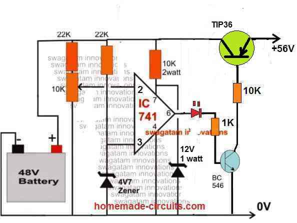
One 22K K is connected in series with the above 10K preset.
Another 22K preset is connected with the pin#3 zener diode.
RED LED connected at pin#6 or the output of the IC.
There’s no room for a Green LED.
Thank u sir, I will try this.
how to control the current in this schematic ? and if its NO position , isn’t the 430v charging input supply is directly short circuiting with the battery bank ?
You are right, the 430 V must be current controlled. You can add a series non-polar capacitor with the AC source of the 430V for controlling current. a 1uF capacitor will restrict the current to around 50 mA. Using this benchmark you can calculate the value of the capacitor depending on how much current limiting your battery requires.
I love this setup. What happens when the batteries are not upto 30
You can adjust the 10K preset to adjust the relay cut off according to the full charge level of the batteries. The charging supply will also need to be appropriately adjusted as per the battery total full charge voltage spec.
hi, I have to design a charger system for 400Vdc and required 1C to full charging of 108Adc.. can U help me?
Hi, what is your battery specification? Is the battery rated at 400 V, 108 Ah?
The batteries are all the same type.
They are 12V 7Ah batteries I think the model# is a D7S(T1)?
lead acid.
Full charge Level Rating? I am not sure what that is.
it has on the label:
TYPE | Voltage Regulation| Initial Current
———————————————————————–
Standard use| 13.6-~13.80V | Less than 2.1A |
Cycle Use | 14.50~14.90V | Less than 2.1A|
———————————————————————–
The 14V battery that you have mentioned is actually a 12V battery I think with 14V being the full charge level. For 24 V setup the full charge voltage level will be 28V, and for the 36V battery setup the full charge voltage level will be 42V.
You will need the IC LM317 HV for making the charger. Once you get the IC you will have to configure the circuit as shown in the following figure. THe orange colored things are resistors which you will need to calculate to get the 14V, 28V, 42V outputs at the respective positions.
Let me know if you have more questions.
Hi Bud,
I am looking for a circuit that can charge my electric lawnmowers. I have 2 mowers, 1 is 36VDC, other is 24VDC, and a 3rd one is 14VDC but that is only part of a WISH LIST. Is there a SELECTABLE charger so I can use 1 single charger for both of these mowers?
Hi, Can you please provide the exact specifications of the 3 batteries, meaning what are their Ah ratings, full charge level ratings, and whether they are lead acid, or Li-ion?
l want to know if it is possible to generate high voltage electricity from feaces.
From where did you get this idea?
Dear Swagatam
Thanks for all your guidance for solving my circuit issues.
I have made a 10 mins to one hour timer using 555 IC for my toilet exhaust fan & is working well. Since it is understood not to exceed the capacitor value to more than 1000mfd,using a 555 IC, I request you to give me a circuit for a 10 min to 2 hour timer which i want to use for my phone charger to avoid it getting overcharged.
I appreciate your kind reply and thank you
Regards
Vee
Dear Vee, can you please post this question under a related article? As you can see the above article is about high voltage battery and not a timer. You can repeat the same question under the following article:
https://www.homemade-circuits.com/interesting-timer-circuits-using-ic-555-explored/
I will surely help you!
Gud evening ,I am very interested in your work,pls I need your assistance for project.i want to design a an automatic battery charger voltage 110vdc charging voltage.pls how do I do it cos I want the battery to stop charging or cut off when reach 115vdc and star charging when voltage drop below 110Vdc. and the charger circuit be of high current capacity.though I have three phase transformer 7.5kva pls help me out
Hi, the above circuit will do exactly what you are looking for. The Rx resistor will have to be experimented to get the lower threshold charging initialization.
Hi!
I’m supposed to design a charger for a formula1 car that has a 600vdc battery at 80kW.
The charging input is 230V and 16A.
Do you have any circuit examples or designs on that? I cant find any.
The charger should have AMS, Temperature, Shutdowncircuit and a manual shutdown button
Hi, that looks almost impractical. Because, first the 230V will be boosted 600+V, which will reduce the current to less than 7 amps. Now charging a 80kW battery with 7amps may take weeks to get it fully charge…so I don’t it may sensible to use the specified source for charging…nonetheless I will try to present an article on this soon with all the possible details.
Hello I l’ve ben looking for a few months for a high voltage charging system and had no luck until now and love your build. This is my situation, I have a ups station 192vdc input 3ph 120/240AC output (12.1kva 10kw). I want to build a off grid system but need a way to charge the batteries with a low voltage cut off and over voltage protection. also with 3 stage because in using sealed led acid battery(170ah 12v) 16 in series my source will be pma alternator.
Glad you found the right design for your application. A 3 stage may make the design very complicated, so I wouldn’t recommend that. You can build the same design as explained above, and get the required results effectively. For 3 phase to DC conversion, you will need a 6 diode bridge rectifier which will covert the 3 phase into the required DC for charging the batts. Just make sure the alternator output is not rated more than 20 amps
Thanks for your reply, okay well I don’t think the batteries would ever be at the point for trickle charging anyway, just bulk Charging because the inverter will be in use 24/7. So I just need a charger with a high enough output to charge the batteries back at the same time supplying dc power to the ups.
The charger supply must be correctly rated as per the battery specifications, otherwise the batteries can get permanently damaged. Or may be a current limiter could be added to the circuit to ensure the batteries are charged safely under any circumstances.
Okay, lets say I just want to go with this for right now, what do I need to change/add in your circuit diagram to charge my bank back to full 192vdc from 240vac input source.
First you will need to set the preset, in the following manner:
Initially keep the preset slider to ground position.
Remove Rx resistor.
Connect 192V DC from the battery side (across 220K end and ground line)
Connect a separate 12V across pin7 and ground line.
Slowly adjust the preset until the RED LED just lights up and the relay clicks.
That’s all your circuit is set for the 192V cut off.
Finally join the Rx across the points, this could an arbitrarily selected 100K resistor or may be a precisely calculated value
This circuit is close to what I need, but not quite!
I would like to charge a battery pack consisting of 72 SAFT VL41M LiPo cells wired in series (operational voltage ~270V). Charge time non critical, preferred current <5A, to be charged from 240V AC.
Do you have a circuit diagram that would suit?
Great site by the way.
I think the above concept will work exactly as per your requirement. You may only have to tailor the input supply with respect to your battery specs. However, this circuit will not balance charge the batteries separately, instead charge the entire series block together, therefore it may be essential to first ensure all the cells in the series have exactly identical specs in terms of voltage, current, health, age etc.
Thanks for the fast response. I am aware of the problems of individual Li-Ion cell ageing (in one or more of the 72 SAFT cells); that said do you have a battery charging circuit that will produce ~270V starting from 230V AC? Thanks.
Great site, very impressive!
Thanks, yes I have a related circuit which you find in the following link
https://www.homemade-circuits.com/220v-lithium-ion-battery-bank-charger/
But please beware that the circuit is not isolated from mains AC, so it is extremely dangerous to touch while it is powered.
Hello sir, I want to ask that the DC voltage produced by a rectified voltage from 48v step down transformer, is it the same as 48v DC supply from battery.
Hello Favour, Both are DC but rectified DC will have a lot of ripples.
Thanks sir, please how best to filter the rectified DC
You will need large capacitor after the bridge, more details are furnished here:
https://www.homemade-circuits.com/calculating-filter-capacitor-for/
sir do you have any schematic for a 12v/24V 50/100/150AMP battery charger with automatic cut off when the battery is fully charged and resume charging when the battery drops down to 6v if its 12v battery or 12v if working with 24v?
Jeo, you can try the last circuit shown in the following article:
https://www.homemade-circuits.com/high-current-10-to-20-amp-automatic/
Thankx you sir i really appreciate
thank sir but i like this circuit most
https://www.homemade-circuits.com/opamp-low-high-battery-charger/ can i do it instant of this circuit
yes you can use it, it is more accurate
ok sir but the resistive divider in the circuit is 15k and 220k. am i correct??
yes that’s right, eliminate the entire stage.
Alternatively You can try the following concept instead
https://www.homemade-circuits.com/make-6v-4ah-automatic-battery-charger/