My friend Steven has updated a few more of his findings related to his sec exciter experiment, I have explained more what Mr. Steven has to say.
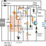
NEW SEC EXCITER POWERED HV CAP CHARGER WITH HV DC OUTPUT
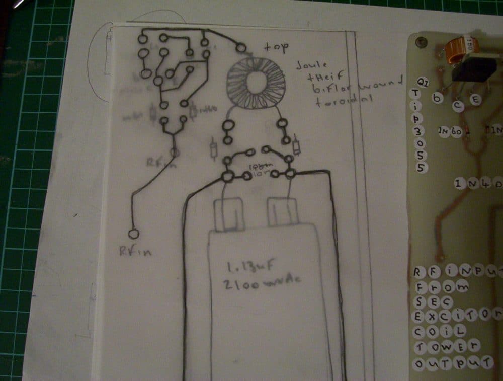
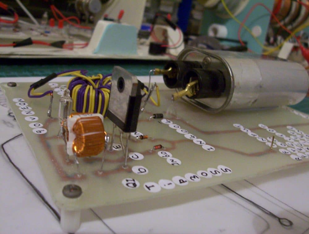
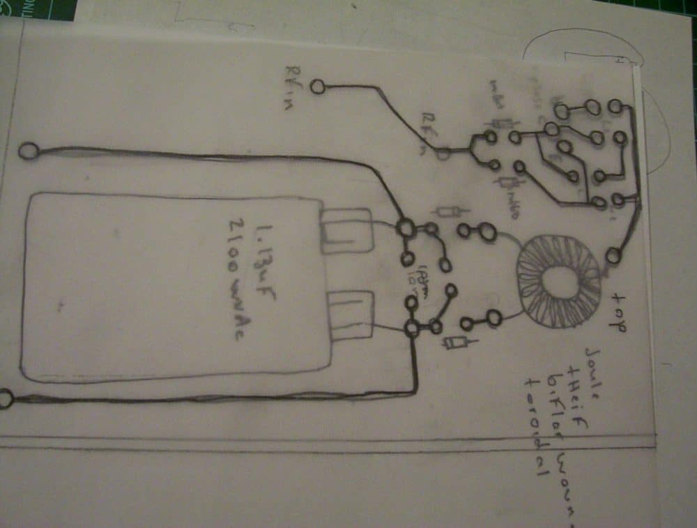
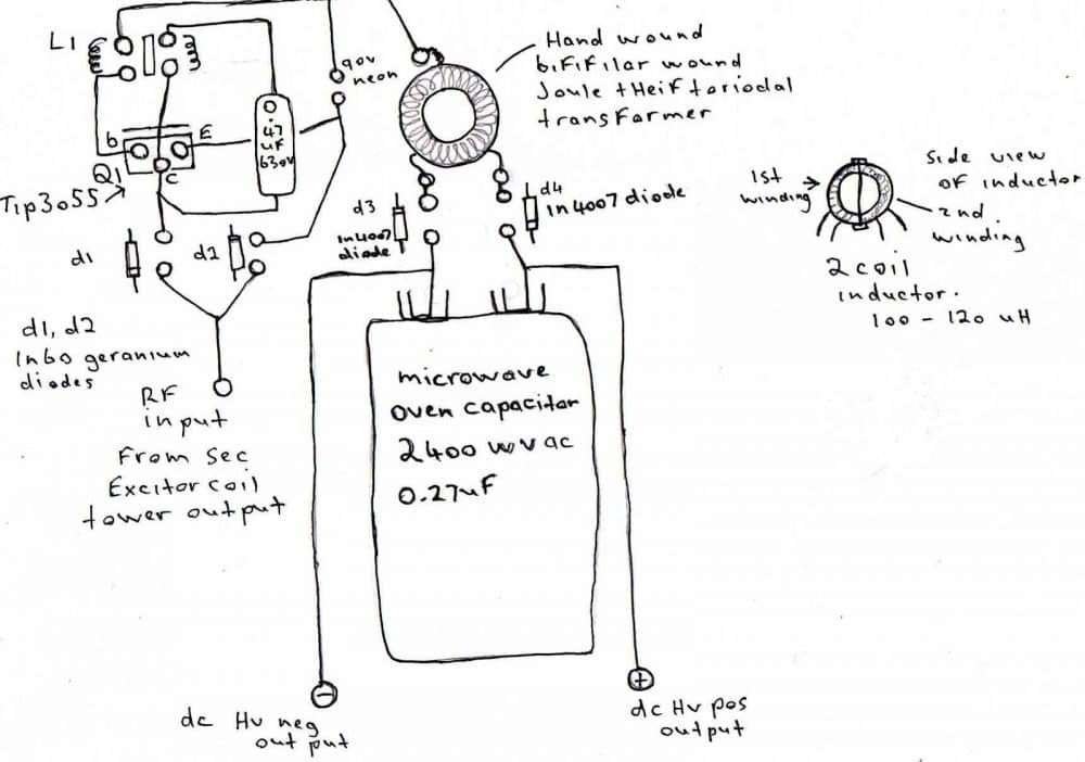
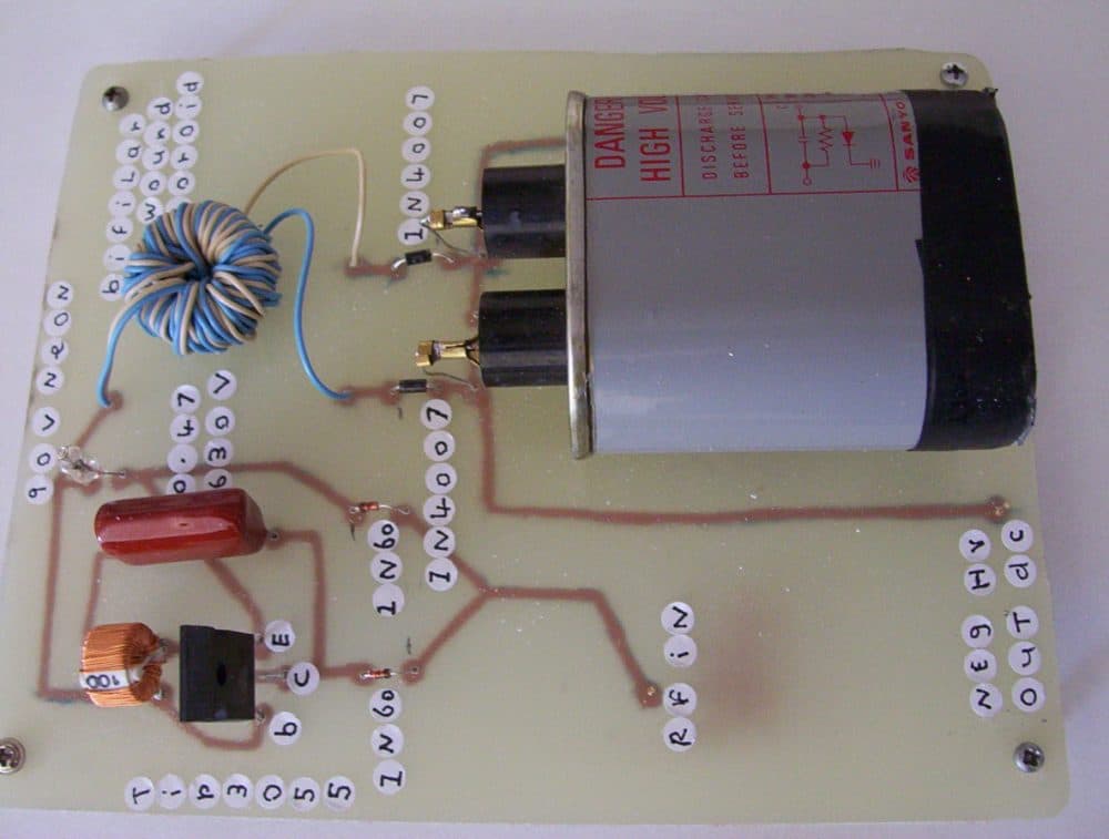
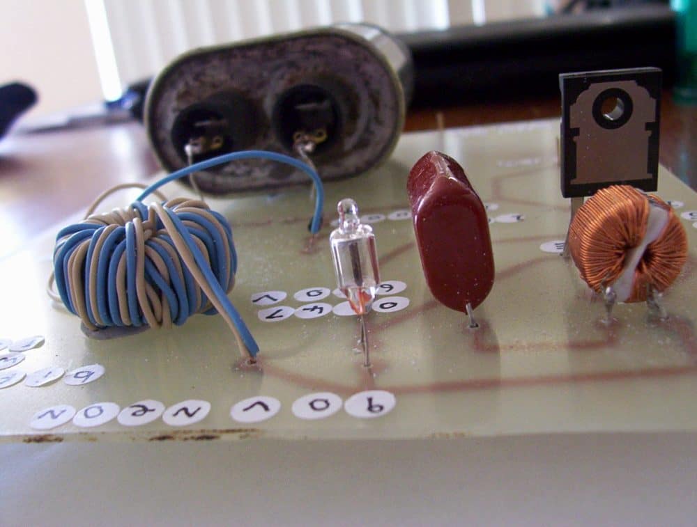
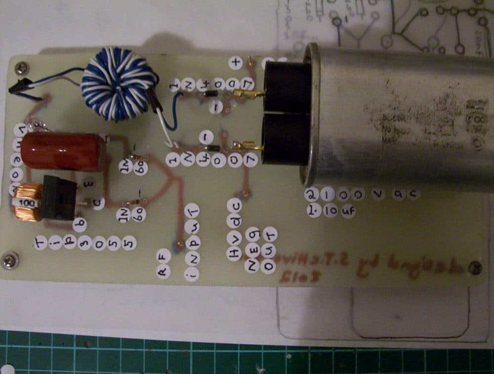
Here's the newest circuit originally it was a 3 piece circuit i found on YouTube so i modified it and upgraded it and threw in some ideas to get this beauty , now it has the tip3055 and inductor as on the YouTube video, and a ac light but you can see all the changes I've done to it to make it suitable to power off the single rf output of the sec exciter tower
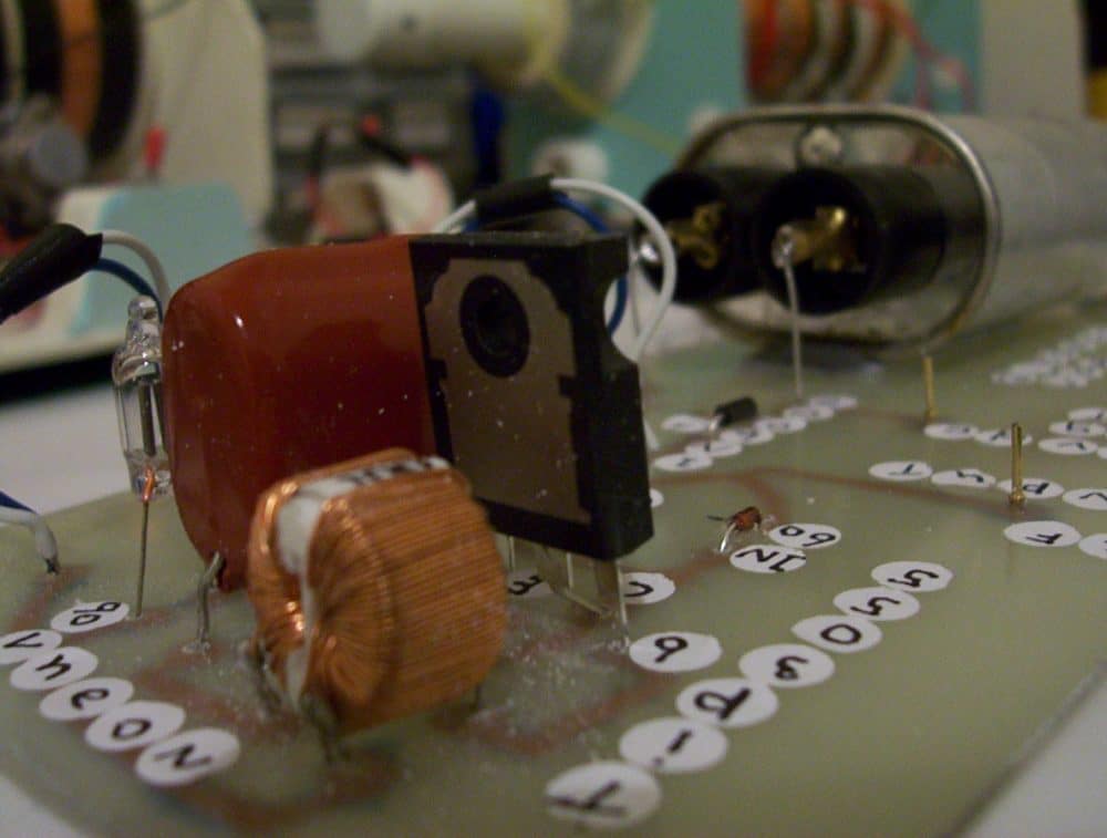
i threw in the microwave cap look carefully the inductor has 2 coils one runs through the collector of the tranny and back to above the second av plug diodes i used in the modified circuit so for all i can say its acting as an rf antennae to and opposite to the other coil so if there's any induction going on then maybe it explains why i get a fast voltage reading till it gets to 454 volts dc then stays there and as for the current output
well its high enough to zap you and i had some problems in measuring the current output so i may have to get it done by using a regulator circuit so i can get a steady reading ,
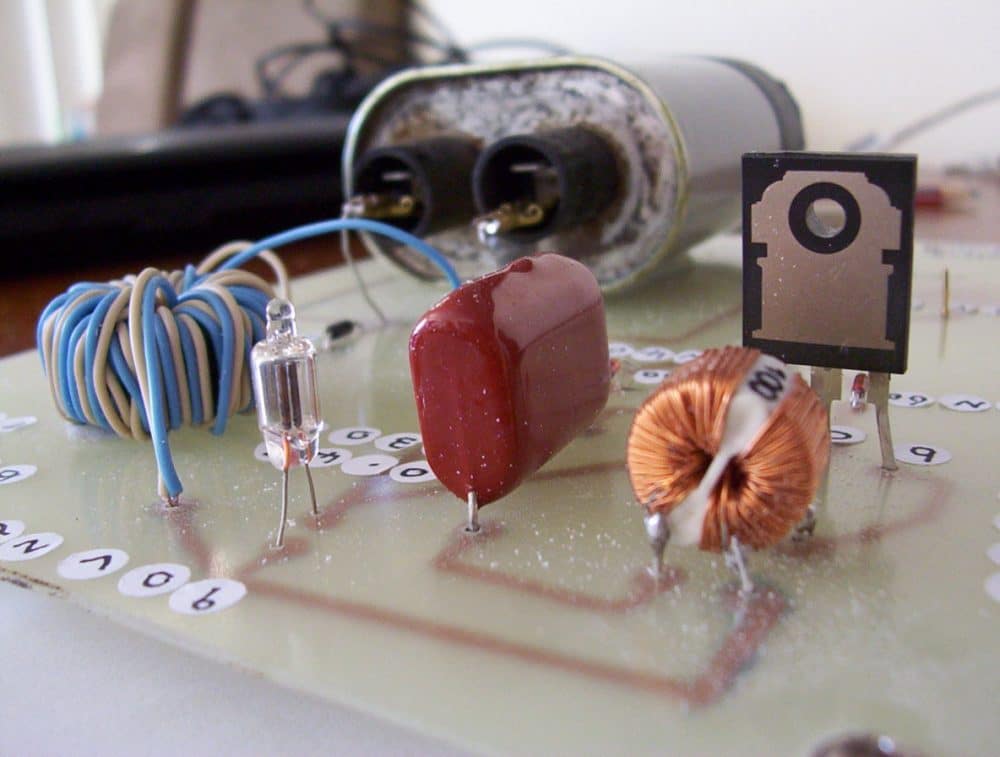
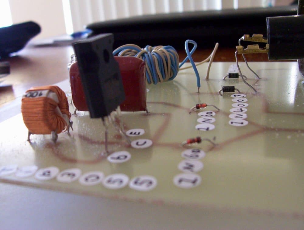
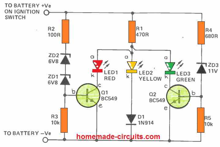
but I'm sure its high enough as when the cap seems to charge and output the dc voltage it sure zaps you when you touch the hv outputs , so this is not bad for a sec exciter powered hv cap charger , i threw in the hand wound bifilar wound joule thief toroid to and all diodes which are 1n60 germanium and the inductor has 120 on top of it it was from my parts draws which i have collected parts from old TVs etc ,
so when i fire my sec exciter up and connect the single RF output to this circuit it doesn't take long to charge up so i have to do some more tests and experiments and see what else i can get out of this , so add this to the circuits that use microwave caps as the only other ones are microwave oven circuits , so my collection of new ideas and circuits i modify to be powered from a single output from an sec exciter grows more and more.
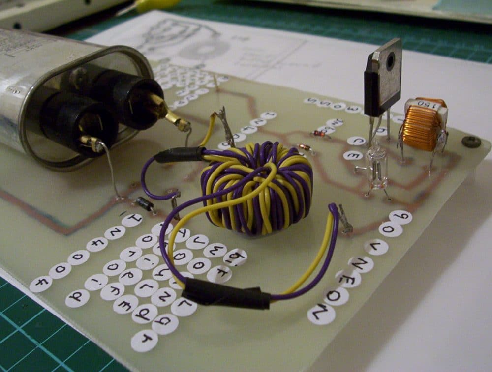
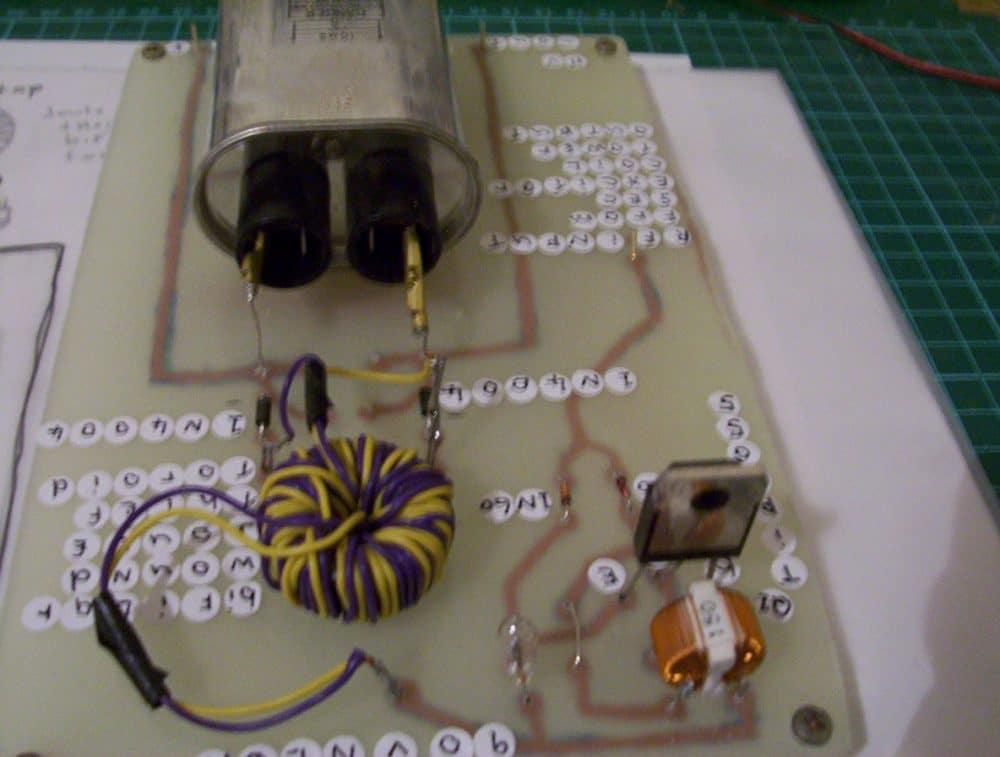
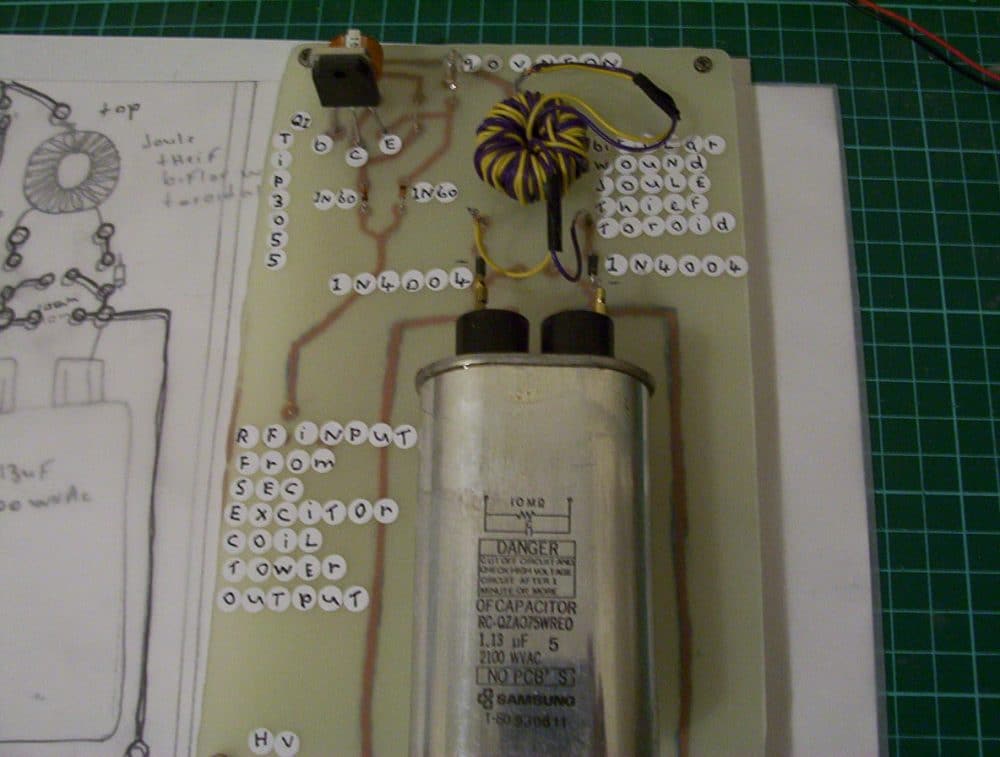
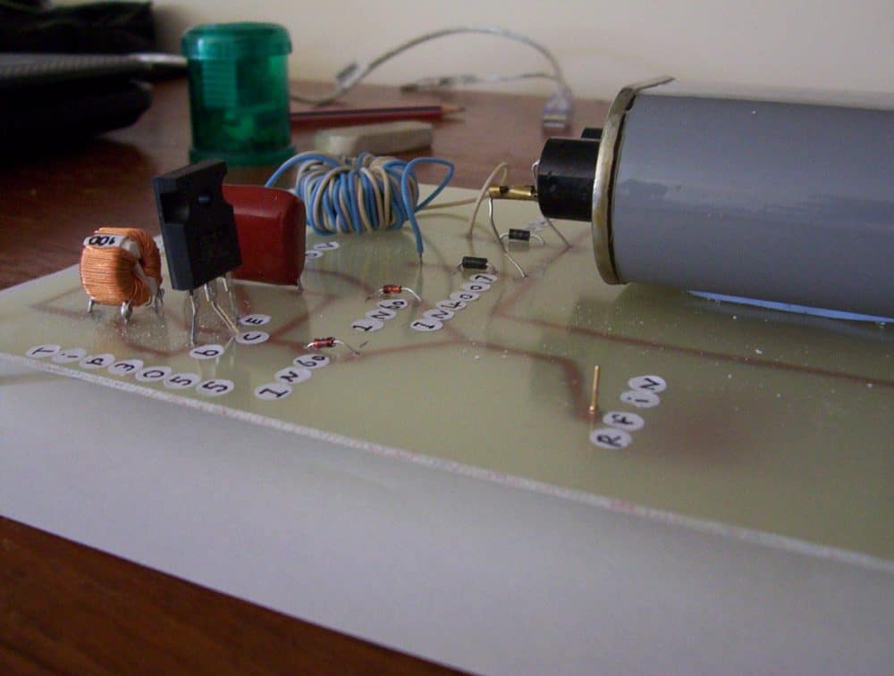
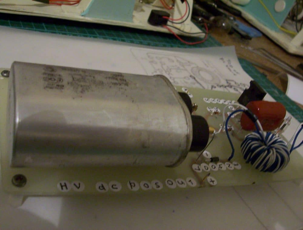
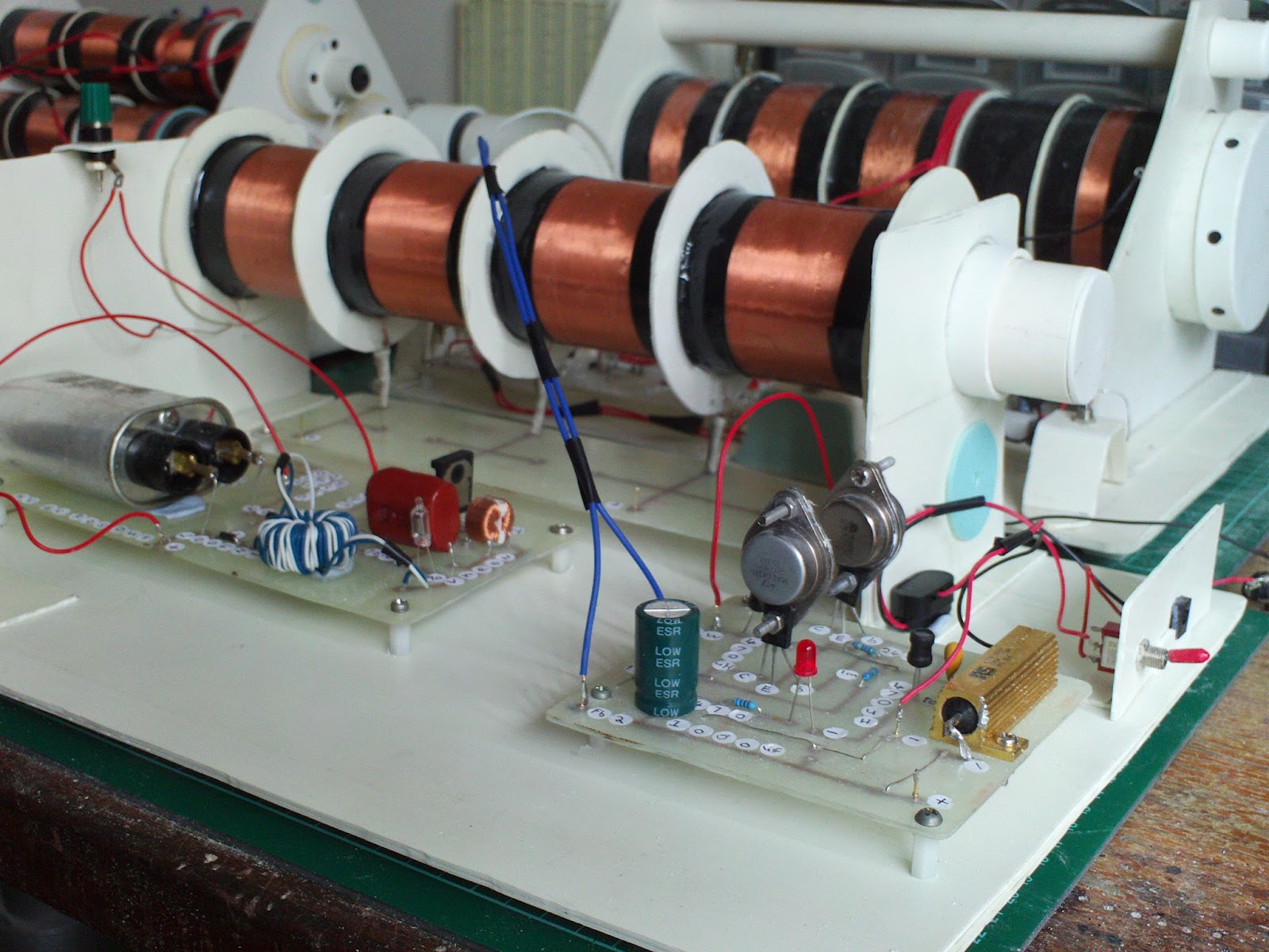
Here are the pics of another newer sec exciter powered hv dc output circuit,
this one puts out more voltage than the other 2 similar circuits and it exceeds the 1100 volts ac rating of the microwave cap even though its dc and the current well up to 13 set to amps on a clamp meter i have top be sure i read it right but it sure gives a shock,

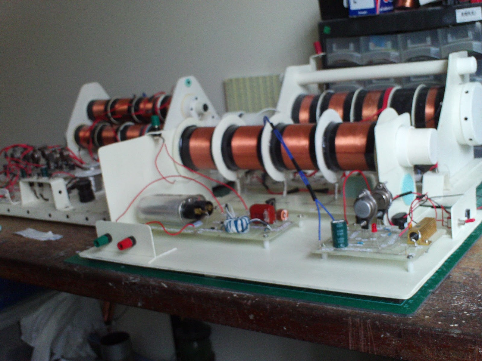
Here are 7 new pictures of the first out of 3 news sec exciters completed,
the series coils have their taps running to a printed circuit board under the coil , these taps are for testing the coil to insure continuity through all the coils . tap number 5 runs to the new circuit via a plug at the top wall this last tap is the power coil tap where all the power comes out of and goes into the hv, dc, ac and rf booster or amp section its outputs run to the terminals on the side the driver circuit and its switch are at the front end where the input starts at no 1.
the series center core goes inside a pvc pipe and it slides in and out for tuning purposes through the center of the series coils you can see the pvc pipe sticking out each end , that is the sliding flux concentrating core housing pipe


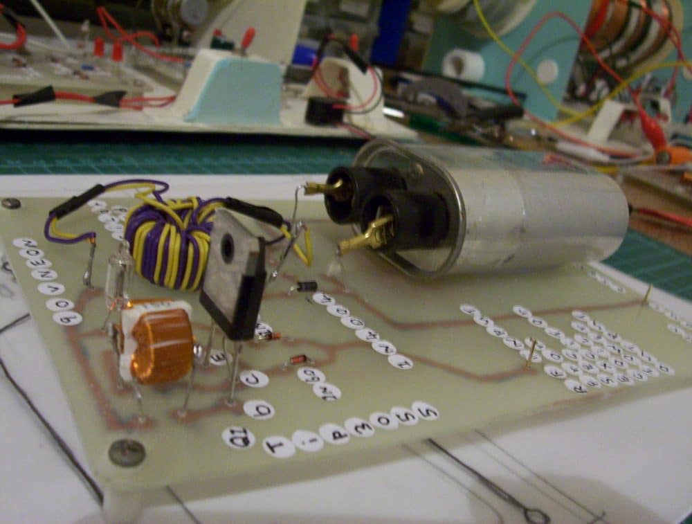
I've done a test of the newest sec exciter coil tower etc etc first the transistors didn't come on and oscillate so that was easy to fix by bridging a metal, object from one transistor to the other .
take note of the power transistors they are used as heat sinks for the bd139 transistors so they have no legs so i bridged the metal object across them both to kick start the transistors into oscillation, when i did that i felt no output at the hv circuit till i inserted the core which i borrowed from my other sec exciter series coil tower projects,
then i held a neon by one leg above each of the series coil sections and the neon lit up well and from a good range to but some spots the neon was less brighter , so i move the flux concentrating core out till the neon started to get brighter ,
i then new that the flux concentrating core was working in tuning the sec exciter for maximum output, as the neon would get brighter near some of the coil sections and the last coil which is the power coil it got bright there to when i pulled the core out so far and that was when the hv dc, hv ac, and RF booster kicked in and gave the high outputs so it all worked ,
I've swapped the feed backs over since the first test as it sometimes helps in the transistors oscillation without having to kick start them,

Questions & Answers
Its like you read my mind! You seem to know a lot about this, like you wrote the book in it or something. I think that you could do with a few pics to drive the message home a bit, but instead of that, this is magnificent blog. A great read. I’ll certainly be back.