In this post I have explained about a simple battery current sensor with indicator circuit which detects the amount of current consumed by the battery while charging. The presented designs also have an auto cut off when the battery stops consuming current at its full charge level..
Why Current Drops as Battery gets Charged
We already know that while a battery charges initially it draws higher amount of current, and as it reaches towards full charge level, this consumption begins dropping, until it reaches to almost zero.
This happens because initially the battery is in the discharged state and its voltage is lower than the source voltage. This causes a relatively bigger potential difference across the two sources.
Due to this wide difference, the potential from the higher source which is charger output, begins rushing towards the battery with much higher intensity causing higher amount of current to enter the battery.
As the battery charges to the full level, the potential difference across the two sources starts closing, until the two sources have identical voltage levels.
When this happen, the voltage from the supply source is unable to push further current towards the battery, resulting in a reduced current consumption.
This explains why a discharged battery draws more current initially and minimum current when it is full charged.
Commonly most battery charging indicators utilize the voltage level of the battery to indicate its charging condition, here instead of voltage the current (amps) magnitude is used for measuring the charging status.
Using current as the measuring parameter enables a more accurate assessment of the battery charging status. The circuit is also capable of indicating the instantaneous health of a connected battery by translating its current consuming capability while its being charged.
Using LM338 Simple Design
A simple current cut off battery charger circuit could be built by suitably modifying a standard LM338 regulator circuit as shown below:
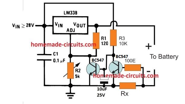
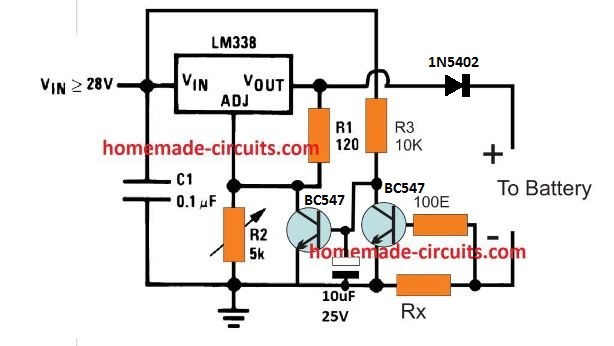
I forgot to add a diode at the battery positive line, so please make sure to add it as shown in the following corrected diagram.
How it Works
The working of the above circuit is rather simple.
We know that when the ADJ pin of the LM338 or LM317 IC is shorted with the ground line, the IC shuts down the output voltage. We use this ADJ shut down feature for implementing the current detected shut off.
When input power is applied, the 10uF capacitor disables the first BC547 so that the LM338 can function normally and produce the required voltage for the connected battery.
This connects the battery and it starts charging by drawing the specified amount of current as per its Ah rating.
This develops a potential difference across the current sensing resistor Rx which switches ON the second BC547 transistor.
This ensures that the first BC547 connected with the ADJ pin of the IC remains disabled while the battery is allowed to charge normally.
As the battery charges, the potential difference across Rx begins dropping. Ultimately when the battery is almost fully charged this potential drops to a level where it becomes too low for the second BC547 base bias, shutting it down.
When the second BC547 shuts down the first BC547 switches ON, and grounds the ADJ pin of the IC.
The LM338 now shuts down completely disconnecting the battery from the charging supply.
Rx can be calclated using Ohm's law formula:
Rx = 0.6 / Minimum Charging Current
This LM338 circuit will support up to 50 Ah battery with the IC mounted on a big heatsink. For batteries with higher Ah rating, the IC may need to be upgraded with a outboard transistor as discussed in this article.
Using IC LM324
The second design is a more elaborate circuit using an LM324 IC which provides accurate step wise battery status detection and also complete switch off of the battery when the current draw reaches the minimum value.
How the LEDs Indicate the Battery Status
When the battery is consuming the maximum current the RED LED will be ON.
As the batery gets charged, and the current across Rx drops proportionately, the RED LED will turn OFF, and the GREEN LED is switch ON.
As the battrey gets charged further, the Green LED will turn OFF, and the Yellow will turn ON.
Next, when the battery is near fully charged level, the Yellow LED will turn OFF, and the white will turn ON.
Finally when the battery is fully charged, the white LED will also turn OFF, meaning all the LEDs will be switched OFF, indicating a zero current consumption by the battery due to a fully charged status.
Circuit Operation
Referring to the shown circuit, we can see four opamps configured as comparators where each op amp has it own presetable current sensing inputs.
A high watt resistor Rx forms the current to voltage converter component which senses the consumed current by the battery or the load and translates it into a corresponding voltage level and feeds it to the opamp inputs.
At the begining, the battery consumes the highest amount of current which produces a corresponding highest amount of voltage drop across the resistor Rx.
The presets are set in such a way that when the battery is consuming the maximum current (fully discharged level), the non-inverting pin3 of all the 4 op amps have a higher potential than the refernce value of pin2.
Since the outputs of all the op amps are high at this point, only the RED LED connected with the A4 lights up while the remaining LED stay shut off.
Now, as the battery gets charged, the voltage across Rx begins dropping.
As per the sequential adjustment of the presets, A4 pin3 voltage drops slightly below the pin2, causing A4 output to go low and RED led to shut off.
With A4 output low, the A3 output LED lights up.
When batttery charges a bit more, A3 op amps pin3 potential drops below its pin2, causing the output of A3 to go low, which shuts off the GREEN LED.
With A3 output low, A2 output LED lights up.
When the battery gets charged a little more, the pin3 potential of A3 drops below its pin2, which causes the output of A2 to become zero, shutting off the yellow LED.
With A2 output low, the white LED now lights up.
Finally when the battery is almost fully charged, the potential at pin3 of A1 goes below its pin2, causing A1 output to become zero, and the white LED shuts.
With all the the LEDs shut off, indicates the battery is fully charged, and the current across the Rx has reached zero.
Circuit Diagram
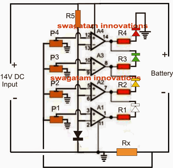
Parts List for the proposed battery current indicator circuit
- R1----R5 = 1k
- P1-----P4 = 1k presets
- A1-----A4 = LM324 IC
- Diode = 1N4007 or 1N4148
- Rx = As I have explained below
Setting the Current Sensing Range
First, we have to calculate the range of the maximum and minimum voltage developed across Rx in response to the range of current consumed by the battery.
Let's assume the battery to be charged is a 12 V 100 Ah battery, and the maximum intended current range for this is 10 amps. And we want this current to develop around 3 V across Rx.
Using Ohm's law we can calculate the Rx value in the following manner:
Rx = 3 / 10 = 0.3 Ohms
Wattage = 3 x 10 = 30 watts.
Now, 3 V is the maximum range in hand. Now, since the refernce value at pin2 of the op amp is set using a 1N4148 diode, the potential at pin2 will be around 0.6 V.
So the minimum range can be 0.6 V. Therefore this gives us the minimum and maximum range between 0.6 V and 3 V.
We have to set the presets such that at 3 V, all the pin3 voltages of A1 to A4 are higher than pin 2.
Next, we can assume the op amps to turn off in the following sequence:
At 2.5 V across Rx A4 output goes low, at 2 V A3 output goes low, at 1.5 V A2 output goes low, at 0.5 V A1 output goes low
Remember, although at 0.5 V across Rx all the LEDs shut off, but 0.5 V may still correspond to 1 amp current being drawn by the battery. We can consider this as the float charge level, and allow the battery to remain connected for some time, until we finally remove it.
If you want the last LED (white) to stay illuminated until almost zero volt is reached across Rx, in that case you can remove the reference diode from the pin2 of the op amps, and replace it with a resistor such that this resistor along with R5 creates a voltage drop of around 0.2 V at pin2.
This will ensure that the white LED at A1 shuts off only when the potential across Rx drops below 0.2 V, which in turn will correspond an almost fully charged and removable battery.
How to set the Presets.
For this you will need a dummy potential divider built using a 1K pot connected across the supply terminals as shown below.
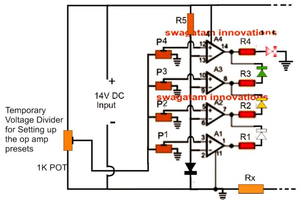
Initially, disconnect the P1---P4 preset link from the Rx and connect it with the center pin of the 1 K pot, as indicated above.
Slide the center arm of all the op amp presets towards the 1K pot.
Now, adjust the 1K pot so that 2.5V is developed across its center arm and the ground arm. You will find only the RED LED is ON at this point. Next, adjust the A4 preset P4 so that the RED LED just shuts off. This will instantly switch ON A3 Green LED.
After this adjust the 1K pot to reduce its center pin voltage to 2V. As above, adjust the A3 preset P3 so that the Green just shuts OFF. This will switch ON the yellow LED.
Next, adjust the 1K pot to produce 1.5V at its center pin, and adjust the A2 preset P2 so that the Yellow LED just shuts off. This will switch ON the white LED.
Finally, adjust the 1K pot to reduce its center pin potential to 0.5V. Adjust the A1 preset P1 such that the white LED just shuts off.
The preset adjustments is now over and done!
Remove the 1K pot and reconnect the preset output link back to Rx as show in the first diagram.
You can can start charging the recommended battery and watch the LEDs respond accordingly.
Adding a Auto Cut OFF
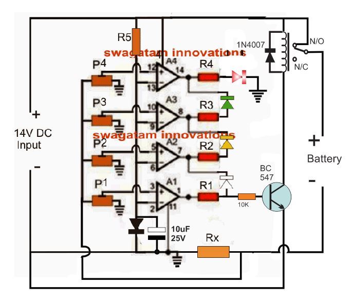
When the current reduces to almost zero, a relay could be switched off for ensuring an auto cut to the current sensed battery circuit circuit, as shown below:
How it Works
When power is switched ON, the 10uF capacitor causes a momentary grounding of the pin2 potential of the op amps, which allows the output of all the op amps to go high.
The relay driver transistor connected at A1 output switches ON the relay, which connects the battery with the charging supply via the N/O contacts.
The battery now starts drawing the stipulated amount of current causing the required potential to develop across Rx, which is sensed by the pin3 of the op amps via the respective presets, P1---P4.
In the meantime, the 10uF is charged via R5 which restores the reference value at pin2 of the op amps back to 0.6V (diode drop).
As the battery charges the op amp outputs respond correspondingly as explained previously, until the battery gets fully charged, causing A1 output to go low.
With A1 output low, the transistor switches OFF the relay and the battery is disconnected from the supply.
Another Useful Current Sensed Battery Cut-off Design
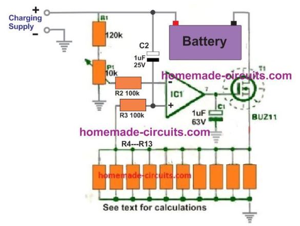
The working of this design is actually simple. The voltage at the inverting input is fixed by the P1 preset at a level that is just lower than the voltage drop across the resistor bank R3---R13, corresponding to the recommended charging current of the battery.
When power is switched ON, C2 causes a high to appear at the non-inverting of the op amp which in turn causes the op amp output to go high and switch ON the MOSFET.
The MOSFET conducts and allows the battery to be connected across the charging supply, enabling the charging current to pass through the resistor bank.
This allows a voltage to develop at the non-inverting input of the IC, higher than its inverting pin, which latches the output of the op amp to a permanent high.
The MOSFET now continues to conduct and the battery is charged, until the current intake of the battery decreases significantly at the full charge level of the battery. The voltage across the resistor bank now drops, so that the inverting pin of the op amp now goes higher than the non-inverting pin of the op amp.
Due to this, the op amp output turns low, the MOSFET is switched OFF, and the battery charging is finally halted.



Have a question or feedback? Feel free to ask below—just make sure it relates to the post above!