• Skip to main content
  • Skip to primary sidebar

Homemade Circuit Projects

Need circuit help? Post them in the comments! I've answered over 50,000!

Blog | Categories | About | Hire Me | Contact | Calculators-online
You are here: Home / Automobile Electronics / LC Resonance Calculator for EV Battery Charger Circuits

LC Resonance Calculator for EV Battery Charger Circuits

Last Updated on July 11, 2026 by Swagatam Leave a Comment

This calculator helps estimate resonant frequency or compensation capacitor for a wireless EV charging primary coil. It is for first-step design and learning, not final tuning...

Table of Contents
  • EV Wireless LC Resonance Calculator
    • 1) What You Are Actually Calculating
    • 2) Measure Coil Inductance First (Very Important)
    • 3) Choose What You Want To Calculate
    • 4) Enter The Two Known Values
    • 5) Enter The Coupling Coefficient (k)
    • 6) Click CALCULATE
    • 7) Choosing Nearest Standard Capacitor Value
    • 8) Important Check
    • 9) Recommended Oscillator Or Driver Setup (Wireless Charge Transmitter)
Calculator by homemade-circuits.com
<a href="https://www.homemade-circuits.com/3-led-battery-level-indicator-circuit/">EV</a> Wireless LC Resonance Calculator

EV Wireless LC Resonance Calculator

Stay within 50–100 kHz for mid-range EV wireless power. Remember that secondary coupling modifies the effective primary inductance. Use measured L values.

1) What You Are Actually Calculating

In wireless charging, primary coil is always used with a resonance capacitor, together forming an LC tank. This calculator finds one unknown when two others are already known.

  • Coil inductance (L).
  • Resonant capacitor (C).
  • Target operating frequency (f).

You must already know at least two, otherwise nothing works.

2) Measure Coil Inductance First (Very Important)

Before using the calculator, let us be clear.

  • Build the actual primary coil.
  • Mount ferrite backing if used.
  • Measure inductance using an LCR meter.

Always measure inductance in microhenry (µH). Do not rely only on online coil formulas. This measured value is what you enter as Primary Inductance.

3) Choose What You Want To Calculate

At the top, select Calculate.

  • Resonant Frequency: when L and C are known.
  • Capacitance: when L and frequency are known.
  • Inductance: when C and frequency are known.

For beginners, mostly you will use Capacitance (µF), that is common case.

4) Enter The Two Known Values

Typical example.

You measured:
Primary inductance = 110 µH.

You want:
Operating frequency = 85,000 Hz.

So enter:
One field: 110 and select Primary Inductance µH.
Other field: 85000 and select Frequency Hz.

Order does not matter, calculator will handle it.

5) Enter The Coupling Coefficient (k)

This shows how well primary and secondary coils couple magnetically.

If unsure, use safe beginner values.

  • Coils very close and aligned: k = 0.3 to 0.4.
  • Moderate air gap or slight misalignment: k = 0.2 to 0.3.
  • Poor alignment: k = 0.15.

For first designs, 0.25 is a good starting value. This matters since coupling changes effective inductance. Ignoring k gives wrong resonance prediction.

6) Click CALCULATE

Calculator will show either:

Estimated resonant frequency or required resonance capacitor value.

This is starting design value we can use....

7) Choosing Nearest Standard Capacitor Value

Exact capacitor value never exists in real life.

Example:
Calculated value = 0.148 µF.

Use:
0.15 µF, or combine capacitors in parallel.

Always use polypropylene film capacitors, high voltage rating, low ESR. Electrolytic capacitors are not suitable.

8) Important Check

This calculator gives theoretical resonant point only.

  • In real wireless EV charging:
  • Vehicle position changes
  • Coupling changes
  • Load changes
  • Frequency shifts slightly

So expect fine-tuning, expect small frequency or capacitor adjustment, this is normal and unavoidable. All commercial systems do this.

9) Recommended Oscillator Or Driver Setup (Wireless Charge Transmitter)

Once resonance values are known, use one of these.

Best option, industry standard.

Phase-shifted full H-bridge
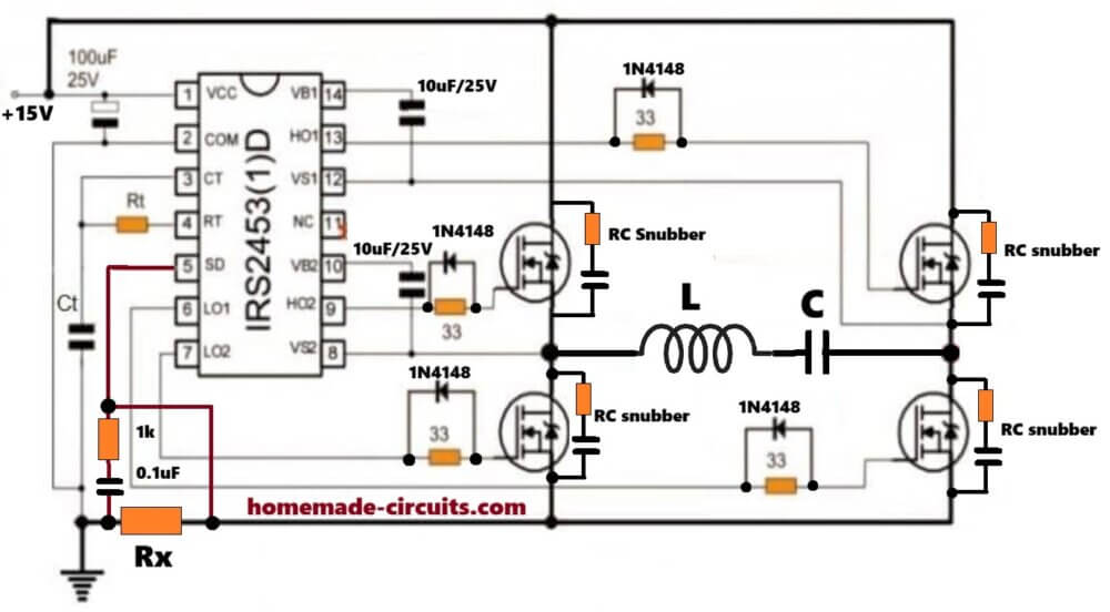
  • Fixed frequency
  • Controlled power
  • ZVS Control through deadtime control
  • Suitable as EV chargers

Medium power option.

Half-bridge resonant inverter
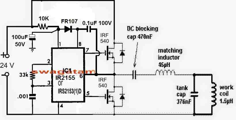
  • Simpler
  • Good efficiency
  • Still controllable

Learning only.

Self-oscillating ZVS (Royer/Mazzilli)
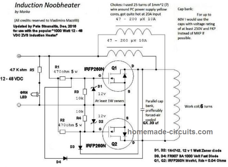
  • Easy to build
  • Frequency drifts
  • Not suitable for professional EV systems

You'll also like:

  • carsecuritycallbackcircuitCell Phone Call Alert Security Circuit
  • Self Regulating Battery Charger Circuit
  • SequentialLEDPart2Sequential Bar Graph Turn Light Indicator Circuit for Car
  • AutomaticAutomobileLightDipperCircuitDiagram252CImageAutomatic Vehicle Headlight Dipper/Dimmer Circuit

Filed Under: Automobile Electronics, Battery Charger Circuits Tagged With: Battery, Calculator, Charger, EV, Tool, Wireless

About Swagatam

I am an electronics engineer and doing practical hands-on work from more than 15 years now. Building real circuits, testing them and also making PCB layouts by myself. I really love doing all these things like inventing something new, designing electronics and also helping other people like hobby guys who want to make their own cool circuits at home.

And that is the main reason why I started this website homemade-circuits.com, to share different types of circuit ideas..

If you are having any kind of doubt or question related to circuits then just write down your question in the comment box below, I am like always checking, so I guarantee I will reply you for sure!


Previous Post: « How To Use And Program ATmega Microcontrollers From Scratch Without Arduino
Next Post: Make this EV Battery Charger Circuit »

Reader Interactions

Need Help? Please Leave a Comment! We value your input—Kindly keep it relevant to the above topic! Cancel reply

Your email address will not be published. Required fields are marked *

Primary Sidebar


Categories

  • Arduino Projects (95)
  • Audio and Amplifier Projects (134)
  • Automation Projects (18)
  • Automobile Electronics (104)
  • Battery Charger Circuits (90)
  • Datasheets and Components (109)
  • Electronics Theory (150)
  • Energy from Magnets and Earth (41)
  • Games and Sports Projects (11)
  • Grid and 3-Phase (20)
  • Health related Projects (27)
  • Home Electrical Circuits (13)
  • Indicator Circuits (16)
  • Inverter Circuits (98)
  • Lamps and Lights (161)
  • Meters and Testers (72)
  • Mini Projects (28)
  • Motor Controller (68)
  • Oscillator Circuits (30)
  • Pets and Pests (15)
  • Power Supply Circuits (91)
  • Remote Control Circuits (50)
  • Security and Alarm (65)
  • Sensors and Detectors (107)
  • SMPS and Converters (46)
  • Solar Controller Circuits (62)
  • Temperature Controllers (44)
  • Timer and Delay Relay (50)
  • Voltage Control and Protection (44)
  • Water Controller (37)
  • Wireless Circuits (31)


Circuit Simulator

circuit simulator image


Subscribe to get New Circuits in your Email


Other Links

  • Privacy Policy
  • Cookie Policy
  • Disclaimer
  • Copyright
  • Videos
  • Sitemap

People also Search

555 Circuits | 741 Circuits | LM324 Circuits | LM338 Circuits | 4017 Circuits | Ultrasonic Projects | SMPS Projects | Christmas Projects | MOSFETs | Radio Circuits | Laser Circuits | PIR Projects |


Recent Comments

  • Swagatam on Simple Low Dropout Regulator Circuits Explained
  • Swagatam on How to Calculate Transformerless Power Supply Circuits
  • Swagatam on 5 Simple Water Level Controller Circuits
  • Swagatam on Control a Relay ON OFF Using SIM Card, Mobile Phone, and Arduino
  • Louis83 on Control a Relay ON OFF Using SIM Card, Mobile Phone, and Arduino

Social Profiles

  • Twitter
  • YouTube
  • Instagram
  • Pinterest
  • My Facebook-Page
  • Stack Exchange
  • Linkedin

Calculators

  • ZVS Induction Heater + Tank Calculator Tool
  • Zener Diode Calculator
  • Wire Current and Thickness Calculator (Ampacity Calculator)
  • Voltage Divider Calculator
  • Transistor Base Resistor Calculator
  • Transistor Astable Multivibrator Calculator
  • TL431 Calculator
  • Solar Panel, Inverter, Battery Calculator
  • Ferrite Core Air Gap Calculator Tool
  • Parallel MOSFET Calculator Tool: How to Connect MOSFETs in Parallel Safely
  • LC Resonance Calculator for EV Battery Charger Circuits
  • LED String Series Resistor Calculator
  • Calculator to Design a High Power 3kW PFC (Power Factor Correction) Circuit
  • Passive Power Factor Correction (PFC) Calculator
  • LM567 IC Calculator Tool
  • SMPS Flyback Boost Converter Calculator
  • Shunt Resistor Calculator for Ammeters
  • SCR and Triac Gate Resistor Calculator
  • Battery Back up Time Calculator
  • Boost Converter Calculator (Non-Isolated)
  • Bootstrap Capacitor Calculator
  • Buck Converter Calculator
  • Buck-Boost Converter Calculator
  • Capacitance Reactance Calculator
  • DCM Flyback Transformer & Wire Gauge Wire Size Calculator Tool
  • Filter Capacitor Calculator
  • IC 4047 Calculator (Frequency and PWM)
  • IC 4060 Calculator
  • IC 555 Astable Calculator
  • IC 555 Monostable Calculator
  • IC SG3525, SG3524 Calculator
  • Inductance Calculator
  • Induction Heater Inductor and Resonant Frequency Calculator
  • Induction Heater Work Coil Calculator
  • Inverter LC Filter Calculator
  • LC Resonance Calculator
  • LED Current Calculator
  • LM317, LM338, LM396 Calculator
  • NAND/NOT Gate RC Values Calculator
  • NOT, NAND Gate Frequency Calculator
  • Notch Filter Calculator Tool
  • Ohm’s Law Calculator
  • Phase Angle Phase Shift Calculator
  • Power Factor (PF) Calculator
  • RC Filter Calculator
  • Reactance Calculator
  • Sine Table Calculator for SPWM Arduino Code
  • Small Signal Transistor(BJT) and Diode Quick Datasheet
  • SMPS Calculator for Toroidal Ferrite Transformers
  • SMPS Flyback Transformer Calculator – Design by Target Duty Cycle
  • TL431 Calculator

© 2026 · Swagatam Innovations