So here we are talking about one small board called T856-C. We use this little module when we want to make one DIY power bank at home, like those we use to charge phones and other USB things. It can charge one 3.7V Li-ion battery like 18650 and also give us 5V output to run or charge other gadgets from USB.
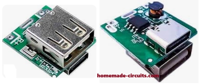
Ports and Pins – What We See On This Module
USB Type-C Port:
This port is used for charging the battery. We give 5V DC input here, from phone charger or power adapter.
Current needed is around 1A, not more than that.
USB-A Port (big normal USB):
This one is the output. From here we get 5V output to charge mobile or run USB fan or something. Max current here can go around 1A or a little more, depending on battery power.
Battery Points:
On the board we see + and – markings where we solder the 3.7V Li-ion battery.
If we want long backup then we can join 2 or 3 batteries in parallel (not in series, only parallel) but all batteries must be same voltage and type.
Battery Details – What Battery We Use
Best battery is 3.7V 18650 Li-ion cell, single or more in parallel.
When we give charge, board sends 4.12V to 4.20V to battery side. If we join more than one battery then we always connect them parallel, not series.
LED Indicators – What Lights Tell Us
| LED Light Doing This | What That Means |
|---|---|
| Blinking | Charging is going on now |
| Always ON | Battery is full or giving power out |
How We Connect Things – Step by Step
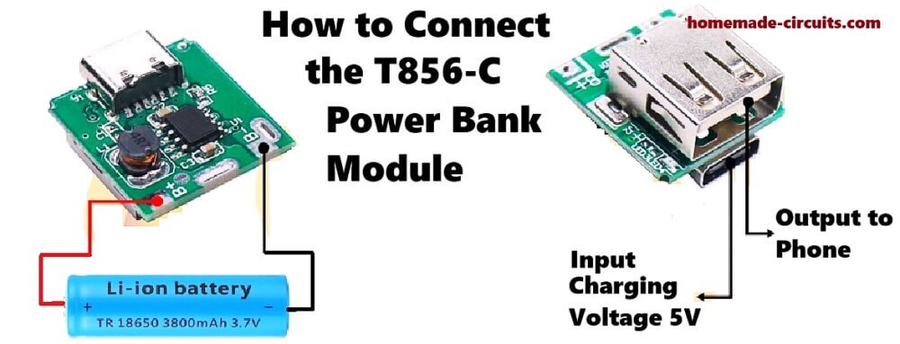
First we solder battery:
Take the + and – of battery, solder to board's battery pads marked + and –. Be very careful, if we reverse battery wires then it can damage the board.
Then we charge:
Take normal 5V USB charger, then connect it to Type-C port. Now charging will start.
Then we use output: When battery is charged, then we plug USB device in the big USB port, and it starts working. Output comes as 5V, can run or charge any USB thing.
Protections Inside This Module
This board is smart and has few protection features like:
- It stops overcharging the battery, and protects from over-discharge.
- If something short happens, it cuts off the output.
- It boosts battery 3.7V to 5V automatically.
Some Tips and Advice
We must use good and healthy battery, not damaged or over-discharged one. If we want long backup then we can connect 2 or 3 batteries in parallel, but all must be same brand and type.
Never try to connect batteries in series, it will mess up the circuit. This small board is good for DIY power bank, also useful for solar charging projects or making small USB power supply.


Questions & Answers
I’m Michael from nigeria and am glad to be one of your students, sir I want to ask if I can add more than one battery to this charging module in parallel?..
You are welcome Michael. You can add one more battery in parallel, but then the charging process will become slow, and take 2 times more time for the batteries to get charged, compared to using a single cell…
ALSO voltage should at least
❤️ be boosted to top of PD spec for PDO
5v PDO: 5.25v
This can be done measuring line resistance?
❤️ Or better sampling PD protocol conversation
I would be surprised if there weren’t a github project or arduino project for this
Amazon reviews cannot be trusted especially not the ones with GREEN VINE headers: Amazon Community Team punishes “too many” negative reviews
Worse though are political activist employees selectively punishing reviewers for content NOT-violating standards.
When you help multiple people write their reviews you notice deeply concerning patterns that undermine amazon profitability.
3 second search finds
https://github.com/manuelbl/usb-pd-arduino
Monitor PD voltage at SINK. Then override output pushing up voltage to ceiling at sink side.
Oh, that’s too much thinking for this small board bro 😄
That GitHub link you sent is for active USB PD communication between smart chips. This tiny T-856 module has no microcontroller and no programmable PD controller inside, so it cannot do any protocol talking or live voltage adjusting. It is just a fixed 5V boost converter chip.
In expensive chargers, yes, sometimes they raise the output a little, around 5.2V or so, to reduce cable voltage drop. But they use special hardware for that. For a cheap DIY power bank module with short cables, normal 5V is more than enough and works fine. No need to make it complicated with Arduino code and line monitoring.
And forget those Amazon Vine reviews bro, we are just making simple hobby circuits for fun 😄 Better keep it simple!
This is not a good charge controller
You need
♦️ one thermal probe
♦️ PD30 output with 5volt 9volt 15volt PDO with PPS
♦️ PD input 5v or 9v
While it violates standards many charge modules provide both QC PD on both type C and type A. These are emulating
ABSOLUTELY avoid Anker “IQ” chargers as they have a long history of deleting the 15volt PDO. And anker back channel communicates with the CORRUPT Amazon Community Team to disappear negative reviews.
If you know a tech magazine editor this would be an interesting exposé atop their “inability” to remove paid fake reviews.
Nope, that’s not correct. First of all this a DIY project designed to work superbly under “normal” conditions.
Yet still the module has some smart built-in protections like:
It stops overcharging the battery.
It protects from over-discharge.
If something short happens, it cuts off the output.
And remember the input is from an USB charger which has 5V output, so drastic increase in current will never happen.
So overall, this module is perfectly safe for a standard 3.7V li-ion cell.
Thanks
Dear Sir
i have power bank & one time circuit connect with MOSFET While my time is on power bank gives power & MOSFET ON & while my timer is OFF ,power bank goes into sleepmode.
how can i prevent power bank goes into Standby MODE. May i connect some external load into my circuit?
Hi Nitesh,
Yes, you can try adding any dummy resistor load between 1k and 10k at the power bank output and check if the issue is solved or not…