In this post I have explained what are gel cell batteries and also learn how to build a specialized charger for charging a gel cell battery, with full calculations.
The proposed circuit works in two modes: it starts charging a discharged gel cell battery with constant current, until the full charge voltage is reached across the battery terminals. As soon as the full charge is reached, the circuit changes over from constant current mode to a constant voltage mode.
This changeover from constant current to constant voltage is important for gel cell batteries which protects the battery from overcharging.
What's a Gel Cell Battery
The gel-cell is quite identical to a contemporary automobile battery. The gel-cell supplies high energy density within a sealed multi-cell, maintenance-free, lead-acid battery.
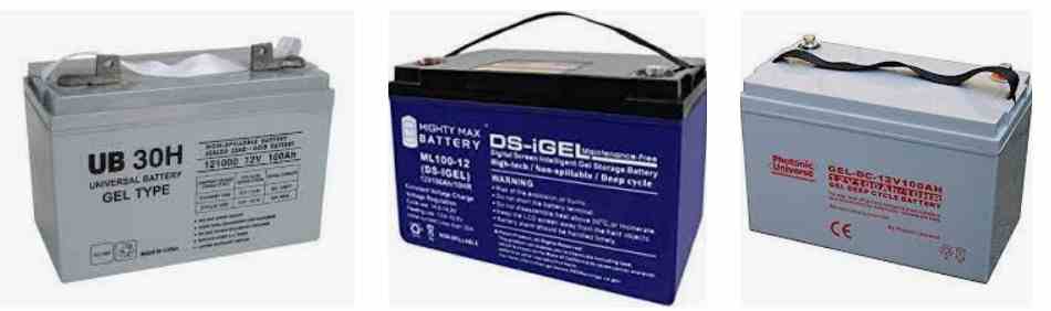
Gel-cells are generally not created in tiny enclosures such as the common AA, C, and D cells.
Instead, these are designed in bigger enclosures which can be available in sizes from a cigarette-pack to a car battery, and in many cases much larger.
Typical gel-cell batteries are available with voltage specs that may vary from 2 to 24, and in Ah capacities which range from 1.2 to 120 Ah (Amp-Hours).
The Ah rating relates to the quantity of current which could be supplied by the battery within a length of time.
For instance, a battery may be specified with 2 volts and 30 Ah. This signifies that the battery must be capable of supplying a current of 1.5 amps consistently during a period of 20 hours.
A correctly handled battery could actually survive for years, however an incorrectly handled battery might remain operative just a few months, or maybe weeks.
The proposed gel-cell battery charger circuit is actually not designed to restore a ruined or mistreated gel-cell battery: it's under your control to take care of your batteries properly.
The quantity of cells in a gel-cell battery can be equivalent to the battery's nominal voltage divided by 2.
A 12 volt battery as a result features six (12/2) cells. Every single cell includes a 2.3 volts output while it is thoroughly charged. Likewise a 6 cell battery nominally specified at 12 volts, in fact provides a fully charged output of 13.8 volts.
It is possible to detect when a gel-cell battery is almost discharged from the simple fact that, when it is without any load or low load situation, it provides an output voltage which is close to its 100 % rated output, but as soon as the battery is subjected to a reasonable to heavy load, voltage falls by approximately 4.6 volts.
The reason behind the two-cell decrease is that a discharged cell basically reverses polarity and starts functioning like a load that "cancels out" the voltage of the good cell.
Therefore you could possibly measure no more than 9.2 volts (13.8 - 4.6 = 9.2) for a 12 volt battery that should be now recharged. And talking about charging, we will now find out how this may be precisely done.
Charging Methods
Gel-cell batteries through various suppliers are created in numerous ways, and these have diverse charging demands.
Many of these batteries could be charged making use of the circuitry I have explained in this article.
That said you need to verify with the manufacturer of your battery in order to be certain. A widespread and trustworthy approach to charging can be as I have explained below.
Initially, a regulated constant current source which is corresponding to 10% of the battery Ah is given to the battery.
As an example, a 12 volt 7 Ah battery could begin using a charging current of 700 mA.
Voltage has to be supervised; as soon as the battery terminal voltage gets to 90% of rated output.
At this stage the circuit disconnects the constant-current source and switches to a regulated voltage in order to accomplish the full charging of the battery.
This changeover is actually important in order to protect against over-charging just in case the battery remains attached with the charger for an extended length of time. The battery could go through a float-charge in this manner forever.
You could work with a charging current other than 10% for instance, intended for "fast-charging." But, if you are using a different current, make sure to comply with the manufacturer's suggestions cautiously.
To figure out how much voltage the gel cell charger circuit needs to produce, multiply the number of cells in your battery by 2.3, then add 5 to account for circuit losses. In order to charge our example 12 volt battery, we'll need a 19 volt unregulated IC supply.
Circuit Description
The constant-current charger circuit is straight from the data book of the manufacturer.
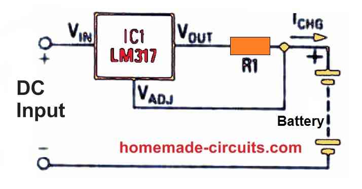
The heart of the charger, as depicted in Figure 1 below, is an LM317 adjustable regulator. If properly heatsinked, an LM317K can deliver up to 1.5 amps of current and can withstand up to 37 volts.
If your battery demands a greater charging voltage, an LM317HV, which can take up to 57 volts, can be used instead.
You might incorporate an LM338, which can generate five amps of current at a maximum of 32 volts, to boost current.
Let's now calculate the value of R1 based on the desired charging current (Icc) and the LM317's 1.25 volt bias:
R1 = 1.25 / Icc
Icc = 0.7 A for a 7 Ah battery, hence R1 = (1.25/0.7) = 1.78 ohms. The wattage of R1 is calculated as follows: 0.7 A x 1.25 V = 0.875 W. Use a 1 watt metal film resistor to just be on the safer side.
Here, the current is taken care of, but what about voltage? Take a look at Fig. 2 below to see what this means.
An LM317 is used as a traditional constant-voltage regulator in this application. R1 should be 240 ohms in most cases, according to the manufacturer.
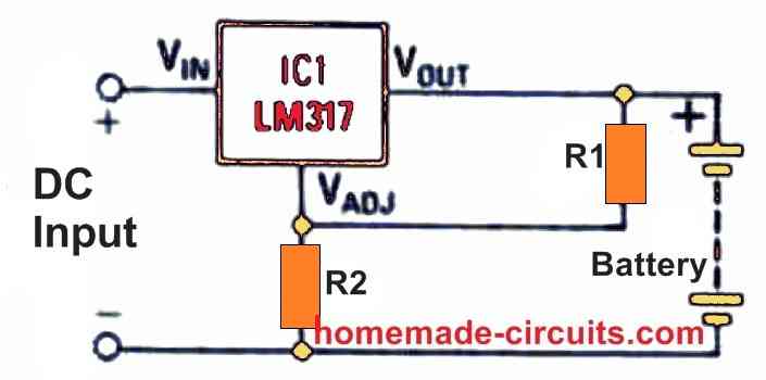
The output voltage is determined by the value of R2, which may be calculated using a complicated formula.
It's normally easier to wire up the circuit using a 5K or 10K potentiometer, select the output voltage, and then replace the potentiometer with the nearest standard fixed resistor.
We now have a voltage regulator and a current regulator. But how do we assemble them to form a combined circuit? Figure 3 shows the situation.
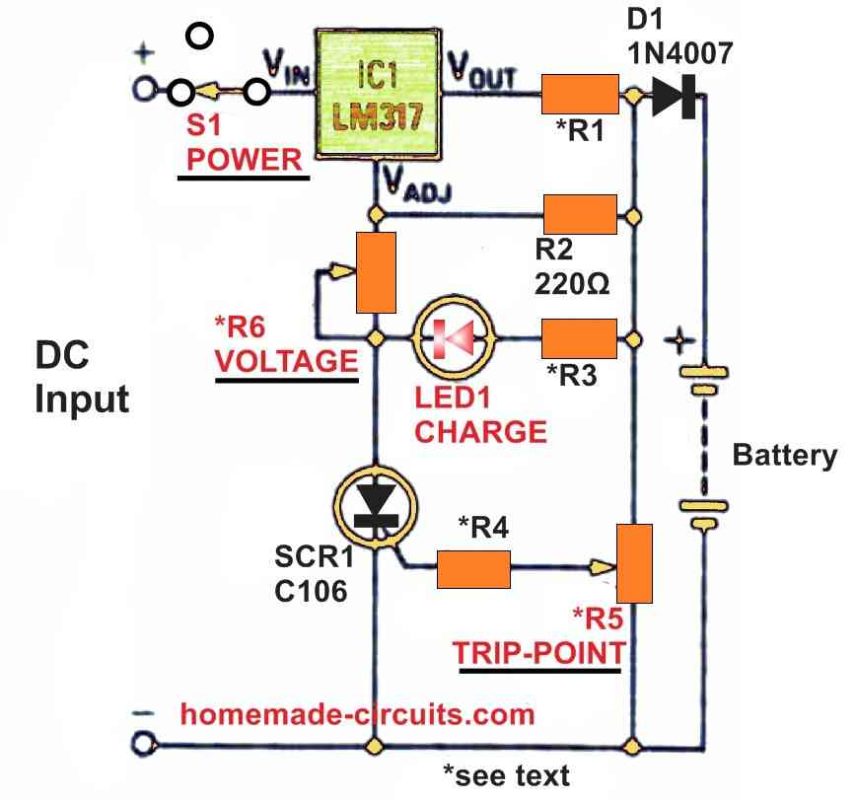
The Complete Gel Cell Battery Charger
Let's go through the circuit's general functionality before looking at how to compute resistor values.
Initially, because SCR1 is turned off when power is connected to the circuit, there is no bias current channel to ground, and the LM317 works as a constant current regulator.
The steering diode D1, limiting resistor R1, and bias resistor R2 connect the LM317 to the battery. This section of the gel cell charger is identical to the circuit depicted in Fig. 1 above.
Once power is disconnected from the circuit, the steering diode prevents the battery from draining through the LED and SCR.
The voltage across the TRIP-POINT potentiometer R5 increases as the battery charges, eventually turning on the SCR.
When the SCR is turned on, it also offers a route to ground for LED1 (through R3).
Because current from the regulator may now pass to ground, the regulator will now operate in the voltage-mode.
When LED1 is turned on, the circuit is in voltage-regulating mode; when LED1 is turned off, the circuit is in current-regulating mode.
Calculating the values of resistors
Let's look at how to compute resistor values now. Consider we're still dealing with a 12 volt, 7 amp-hour battery.
R6 is the voltage adjustment potentiometer, so let's start there. To begin, we must determine a multiplication factor F, which may be calculated by using the following formula:
F = (Vcc / 1.25)+ 1
Vcc is the full charge output voltage of the battery; in our example, Vcc = 13.8, hence:
F = (13.8/1.25) + 1 = 12.04.
The value of R6 is then calculated as follows:
R6 = F(R1 + R2)
We already know that R1 is 1.78 ohms and that R2 is 220 ohms, hence R6 = 12 x (1.78 + 220) = 2661 ohms. This figure is close to what we'll need to get the intended end-of-charge voltage.
To make it simple, just replace R6 with a 4k7 or a 10K pot, that's all, no fuss and no confusions.
Because the voltage drop across the SCR is not taken into consideration, the value is an estimate.
So we just use a 5K potentiometer for R6 and round up to the next highest value. This will allow you to adapt the circuit so that it can be used with different voltage batteries.
R2 should be around 240 ohms, according to the manufacturer of the IC. The series resistance of R1 and R2 is within 5% of 240 ohms, which is acceptable.
If you utilize the high current LM338, you may need to change the value of R2 to accommodate a different charge current, voltage, or both.
The value of TRIP-POINT potentiometer R5, which controls the voltage at which the SCR switches on, now needs to be determined.
For R5 a 5K potentiometer will work nicely if the end-of-charge voltage is less than 20 volts. A 10K potentiometer will work for voltages greater than 20 volts.
R3 is the current-limiting resistor for the LED, and its value is simple to calculate:
R3 = (Vcc - 3) / 20 mA
R3 = (13.8 - 3) / 0.02 = 540 Ω
R3 might be perhaps replaced with a 1K 1/2 watt resistor. This will protect the LED from harm when this gel cell charger circuit is hooked up with batteries with voltages more than 12 V.
The last parameter to compute is R4, which limits the current that may be applied to SCR1's gate.
If the TRIP-POINT potentiometer was rotated too much in the direction of the regulator's output, that current might destroy the SCR1. R4's value may be therefore calculated as follows:
R4 = Vcc / 50 mA
Therefore, R4 = 13.8 / 0.05 = 276 Ω in this scenario.
To give further current limiting, round up to the nearest standard figure of 300 ohms, which should work nicely.
For the indicated SCR, it must be capable of handling the bias current of the LM317K while it is in voltage mode, as well as the full, no load voltage given by your DC source (19 volts in our case).
The SCR mentioned is rated to tolerate 200 volts at 800 mA, thus it should be able to handle any battery you may have.
How to Set Up
In simple way, you can set the gel cell battery charger circuit by directly adjusting the R6 and R5 pots in the following manner:
- Do not connect any battery to the output initially.
- Keep the wiper of R5 pot grounded.
- Connect a 4k7 dummy load at the output of the circuit.
- Connect a volt meter at the output of the circuit, across the 4k7 resistor.
- Switch ON the input supply 19 V to the circuit.
- Adjust the R6 pot until you get an output voltage of 13.8V on the meter.
- Next, adjust the R5 preset until the LED just illuminates at this 13.8V at the output.
- Your circuit is all set now.
What this means?
This means that as long as the battery voltage is below 13.8V, the SCR will be OFF and the circuit will work like a constant current charger.
Meaning, during this time voltage is not controlled, and the battery gets the full voltage that is available at the LM317 output. This voltage may be around 19V which is equal to the input supply.
When the battery terminals reach 13.8V, the SCR triggers ON, and the LM317 IC starts working like a constant voltage regulator, which means now the output voltage is restricted 13.8V.
If you think 13.8V limit is too low, you can raise it to 14V, no issues with this.
While actually charging a gel cell battery, remember to connect the battery first to the circuit and only then switch ON the input supply. If you switch ON the input supply before connecting the battery, then the SCR will detect the 13.8V and switch ON, preventing the initial constant current mode, which will cause the battery to charge slowly, and ineffectively.


Questions & Answers
Hi Swagatam , I trying to figure out if two types of charger are paralleled onto a battery, one charger being a solar regulator 12v 20A and the other a grid powered charger 12v 2A.
When sun is shining 20A is available for charging and at night 2A is available for charging the battery
Will the chargers damage each other or as I understand the battery draws what it can in each instance during daytime and during evening, but the current output from 20A solar regulator wont damage 2A grid charger
Hi Andrew,
The two sources will not damage each other if their positives are isolated through individual rectifier diodes.
You may need two 25 amp and 3 amp diodes, each to be connected in series with the positive lines of the two sources respectively.
Hi Swagatam, One detail I forgot to mention , the the grid powered charger 2A is part of the motor control board. so the battery is feeding power into the control board during power failure, but being charged while grid is active(no power failure). Bidirection power feed on battery terminal.
Another forum mentioned Kirchoff effect which implied that the dominant feed will take over , my concern/question is will high current be a problem. Or is current only sourced by a load as required.
Hi Andrew, Yes the dominant feed will take over, the dominant feed refers to the voltage. The current magnitude is always determined by the load.
If we have isolating diodes as mentioned earlier all concerns become immaterial, and the two sources will have no impact on each other but will keep charging the battery as intended.
However, if a 20A current is fed to a battery rated for 2A charging then definitely the battery can get damaged quickly.
Hi Swagatam,
I would like to know if I can connect a 12V AGM Deep cycle 120A/hr. & a 12V Gel Deep cycle 100A/hr. in parallel, and then drive my 2000W inverter.
If I can use them in parallel would I be able to charge both batteries with this Gel battery charger, or do I need a separate charger for the Gel & and a separate charger for the AGM.
Your advice will be much appreciated.
Regards Jan
Hi Jan,
Yes that’s possible, you can connect the two batteries in parallel. I hope your charger is equipped with an overcharge cut off facility.
Swagatam, Yes my current charger will switch off when 13.8V is reached & also the Inverter is overcharge & undercharge protected.
Can I use your Gel Battery Charger to charge these two batteries in parallel?
What VA should DC in transformer be?
Should I replace the LM371 with a higher amp rating?
Your assistance will be much appreciated.
Regard
Jan
Hi Jan, I would recommend using a simple LM338 circuit for charging your batteries. For increasing the current output you can many of these ICs in parallel. Just make sure to adjust the output to a precise 14V or 14.1V so that the batteries do not get overcharged above 14 V. You can try the concept explained in the following article:
https://www.homemade-circuits.com/how-to-connect-lm338-ic-in-parallel-to-increase-output-current/
Alternatively you can also try the second last circuity from the following article:
https://www.homemade-circuits.com/lm317-with-outboard-current-boost/
Hello mr. Swagatam, thank You for these truly helpful contents, and for your care to readers. I am just a hobbyst and I don’t get the reason why, when the circuit works as a constant current limiter, while the scr is turned off, the limiting resistor is only *R1, and not, as it would appear to me, the series a of *R1+R2, which value would give a much lower current. Can You explain this to me? Best regards
A.
Thank You a lot, I think I am going to choose It just like that, as part of a ‘simple’ online UPS, now looking, here, for a circuit to prevent deep discharge of battery, by automatico load Cut off and then an EMI filter and inverter also. Thank You again
No problem, I have a deep discharge cut off circuit, which you can find in the following link:
Battery Deep Discharge Protection Circuit
However I do not have an EMI circuit for an inverter at this moment.
Thank you Andrea,
When the SCR is cut off, the R2 only acts to trigger the ADJ pin of LM317 so that it can sense the drop across R1, and the current regulation is activated. R2 does not connect in series with R1 and therefore resistances don’t create any interference with each other.
Imagine the following circuit, suppose if a 220 ohm is connected in series with the ADJ link, what would happen? Nothing, the circuit would still continue to work like a current regulator.
Thank you. Very inspiring and helpful website model.
Jack
Thank you for your kind feeedback.
Hello. I’m assembling a battery charger for AGM 5Ah batteries based on the LM317. The constant voltage output will be around 14.4v. I have a transformer rated at 28vac @ 3.6amps which I think will work well.
My test circuit is a bridge rectifier and 1000uF filter capacitor that measures 34vdc no load. I connected a 10ohm load across the output and I get a steady 26.1vdc (2.62amps). My question is what load value would simulate a 12v 5Ah battery?
Thank you for the prompt response. Should the current limiter resistor be placed in series at the output of the rectifier/capacitor and before the LM317 input?
Thank you for your time.
Jack
You will have add a BC547 transistor to accommodate the current limiting resistor. You can see the following diagram for the details. The Rc is the current limiting resistor:
Rc = 0.6 / Max current limit
Hello again…ordered and wired up the current limiting resistor and BC547 transistor circuit. I’m using the LM317 TO3 version of the regulator. Without the battery connected, the output can be adjusted to 14.2vdc. With the battery connected (the battery is charged to 12.56v),
The output measures 12.56v and can’t be adjusted. The potentiometer is a 5k and the resistor connected to the adjustment pin is 240 ohm. I did connect the pot correctly using only 2 of its terminals. Can you briefly describe the function of the transistor? Thank you, Jack.
Hi, Once you connect the battery the output voltage from the 317 will drop to the battery level. It cannot be adjusted because the battery’s discharged level is dragging the output voltage down to 12.56V. In this situation you must allow the battery to get charged. As the battery gets slowly charged the output voltage will rise slowly and reach the 14.2V, after many hours maybe. The transistor does the current limiting. If the current to the battery tries to reach beyond the threshold current, the transistor activates and grounds the 317 ADJ pin cutting it off, this goes on continuously ensuring that the current can never rise above the set threshold.
Threshold current is set by adjusting the resistor Rc value
Rc = 0.6 / Max current limit
Thank you, what you described is exactly what is happening. The initial current reading is 25mA, so to prove the circuit is working I paralleled another power resistor across Rc and the current measures 110mA and the battery voltage is slowly rising. I added a voltage panel meter to the charger output which allows me to set the output to 14.4vdc and then connect the battery and wait for the voltage to rise to 14.4.
Many thanks for your help.
Jack
That is great, glad the problem is solved now. However if you are using 14.4V then you must switch OFF the charger when the battery voltage reaches 14.4V, otherwise you can set it at 14V without the concern of shutting down the charger at 14V.
Yes I see what you mean. I’ve been experimenting with settings from 14.0v to 14.5v and observe the results. I have (4) batteries serving as emergency lights that have a current load of 50mA so I only check and charge the batteries a few times a year.
Time to explore your website for the next project!
Cheers,
Jack
Sure, no problem! let me know if you have more questions.
Hi, For a 5 Ah battery your input current from the transformer must not be over 700 mA. If you are using a 3.6 amp transformer then you must add a current limiter circuit with your IC LM317. This is because the recommended charging current for your 5 Ah AGM battery must not exceed 700mA.
To simulate a 5 Ah battery you can add a resistor that will consume around 700 mA current as the load
Using Ohms law we get:
I = V/R
0.7 = 14.4 / R
R = 14.4 / 0.7 = 20.57 ohms or a 22 ohm will do
Wattage can be = R x I^2 = 22 x 0.7 x 0.7 = 10.78 or simply a 15 watt will do.
बैटरी रिक्सा चार्जर की सर्किट की डिजाइन ,प्रोगरामिंग कराना चाहता हूं।
Battery ka Ah rating batao.
hi sir swag.
i don’t know if this is the right category for asking you about my internet modem 12v/2A. we always have brownout here in our place.i have car and motorcycle batteries.12v65ah-12v/9ah.i want to use it on modem during brownout.
1. how can i connect this to modem with these high ah batteries, can i connect it directly to modem,
2. how to convert ah to amp exactly to know the battery current,and how to calculate charging time and back up time of battery. tnx.
Hi Anton,
You can connect the high Ah battery directly to the modem provided the voltage spec of the battery matches the voltage spec of the modem. Meaning if suppose the modem voltage rating is 12V, then you can connect any 12 V battery to it, regardless of the Ah value.
The Ah value indicates the highest amount of current which the battery can possibly generate and operate the load for 1 hour. For example a 100 Ah battery indicates that it can power a load with 100 amp current for 1 hour max. However, these are only technical specifications, in real life you must never discharge a lead acid battery at its full Ah rate. The recommended charge/discharge rating of a lead battery is 10% of its Ah value….which means it will roughly give a you a backup time of 9 hours with this recommended 10% discharge rate.
sir swag
thank you for very precise answer.now i can use my battery,because that was worries me more that if i connect it directly,the modem might fry badly. we always experience brownout here.big help! thanx
Yes, if your modem voltage and the battery voltage are same, then you can use the battery without worrying about the Ah rating of the battery.
sir swag,
thank you,that adds up even more.keep up sir
Thanks Anton, Glad to help!
Dear Swagatham,
I am looking a BMS for a 12 * 4 100amp c-10 lead-acid battery circuit to keep all the 4 battery equally charged.
I think this could be very simple circuit using mosfets of 100 or 150 amp rated. Any idea ?
Thank you.
Dear Suresh, a BMS is actually not required for a lead acid battery if it charged at 1/10th current of its Ah rating. BMS may be required if a fast charging is employed. If you have a current controller connected with each of the batteries then connecting a constant voltage of 14.2V 50 amp power to all the 4 batts in parallel will do the job nicely.
Dear Swagatam, Thank you for responding.
The batteries are connected in serial to the ups and charging done using Solar panel / MPPT controller. Hence there is no way to do what you mentioned. This is a common setup.
However all the batteries do not get equal charges though theoretically it is so. Due to internal differences of each batteries, they get charged un-equally. Hence not getting the optimum performance from them. BMS is installed to correct this issue so that all the batteries shall be at equal charge.
Su-kam makes such an equalizer which is priced a huge 3600/-. I am sure we can make it for less than 500/-. (100amp mosfet costs only 50/-).
When you get time, pls look into it.
You are welcome Suresh, OK if the batteries are connected in series then you will need a BMS with equalizer which is also called a balance charger circuit. I have one article which explains how to make a balance charger circuit….however I have not tested it practically. Here’s the link to the article for your reference:
https://www.homemade-circuits.com/lipo-battery-balance-charger-circuit/
Hello Mr. Swagatam, thank you for your quick response. I thought that some power transistor could be added for the high amps, because here in Argentina the Lm338 is very expensive.
Hello Carlos, using an outboard transistor is a possible option but then the transistor will not have a short circuit protection….in that case you may have to use an additional current controller circuit at the input side of the charger so that the transistor never burns due to an accidental over-current or short circuit at the output.
Hi Mr Swagatam thank you for your quick response. But is there another way to do it? Because that regulator is not available here in Argentina. I would have to order it from another country and it would be very expensive.
Hi Carlos, in that case you can try using two LM338 ICs in parallel mounted side by side over a single common aluminum heatsink.
Hello sir Swagatam, the circuit is so good. I really like but I have a car battery and I need a circuit like that , but to a car… Can you modified For car batteries? .. Thank you so much.
Thank you Carlos, glad you liked it. If you replace the LM317 with LM196 then you can charge batteries up to 100 Ah, after setting the resistors according to the given formulas.