In this article I have explained the main specifications, datasheet and circuit application notes of the IC LM123, LM323 which are precision 5V, 3 amp fixed voltage regulator IC.
These ICs can be used for generating highly regulated 5 V output with a an impressive 3 amp current output. The maximum input to the IC should not exceed 20 V.
The best application of this regulator IC can be for charging cell phones or smart phones from a 12 V source such as from a car battery, or from renewable energy sources such as solar panels, windmills, small hydro power generators etc.
Introduction
We have learned a lot regarding the IC7805 which is also a 5V fixed voltage regulator having excellent line and load regulation attributes.
However these are specified to produce a maximum of 1 Amp output, and therefore become less useful for higher current applications.
The IC LM123 includes all the impressive features of its above smaller counterpart and yet is enhanced for handling up to 3 Amps of load current.
The main features and specifications of this 5V, 3 Amp fixed voltage regulator can be studied from the following discussion:
Main Technical Features
- Guaranteed 1% Initial Accuracy
- Guaranteed 3 Amp Output Current
- Built-in Current and Thermal Limiting
- 0.01Ω Typical Output Impedance
- Not more than 30W Power Dissipation
- P+ Product Enhancement tested
- No external component required for acquiring the rated 5V output
- Is Virtually Blow-out proof
- Package: Steel TO-3
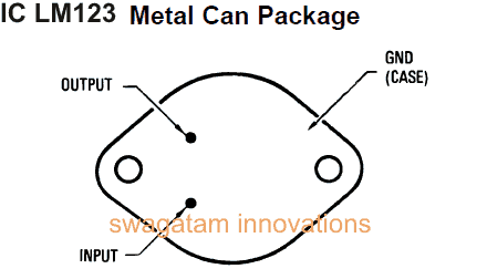
Pin Out Details:
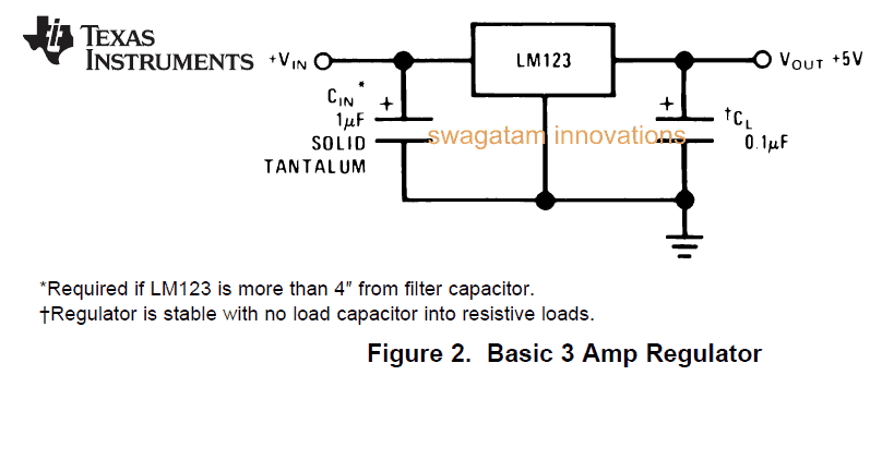
LM123 Electrical Specifications
The following parameters indicate the main operating specs of the IC LM123:
- Input Voltage: Minimum 7.5V, Maximum 15V
- Output Voltage: Minimum 4.7V Maximum 5.3V
- Line Regulation: Typically 5mV at 7.5V and 25mV at 15V
- Load Regulation: Typically 25mV at 7.5V and 100mV at 15V
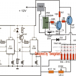
Circuit Diagram of IC LM123, input 7.5V to 15V, output fixed 5V, 3Amp
Application Note:
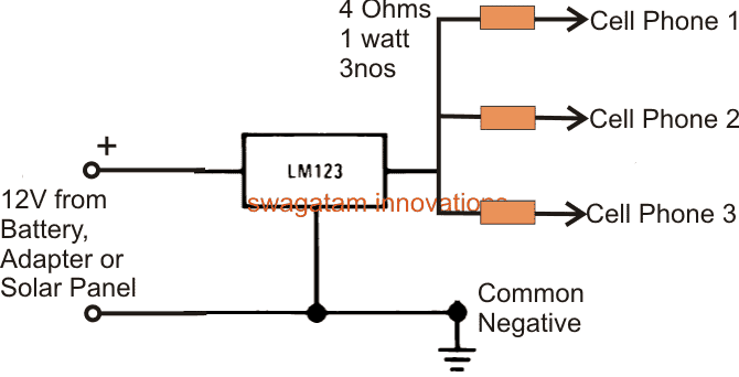
Making a Solar Cell Phone Charger Circuit Using IC LM123
The following circuit shows one typical example where the above IC is effectively used for charging 3 to 4 cell phones simultaneously from a 12V 3 amp source.
The source can be a 12 V lead acid car battery, a AC/DC adapter or a renewable input such as from a solar panel, wind turbine etc.

Questions & Answers
Hello sir me bhanu from Bhubaneswar….
>Sir I have a doubt the transistor LM123, LM232, LM223 this all series are not available in any shop….
Is there some substitute of this …..
>But sir a person told me that you take two LM7805 voltage regulator & series both the regulator and connect a transistor in the middle of it for high current application …..
I cant’ get this point sir can u get it …do you have some idea regarding this
I am not getting that person in that shop….i am still trying to get him…..
>plz sir help me in this Is there some substitute of this …..or any circuit related to this
Thank you sir….
Hello bhanu,
for higher you can try LM338, LM396 etc.
as regarding boosting 78XX current you can take the help of this post:
easy-electronic-circuits.blogspot.in/2012/03/deriving-high-current-from-7805-7812.html
hi,
dear swagatam
can you please provide the circuit digram by which we can convert single phase supply into three phase suplly.
Hi Swagatam,
Welcome. Its just that I need this project for my own home.
Thanks for replying real quick. I will try to make this project a.s.a.p. (although I'm very nervous 😛 LOL) and seek your help when I would need it.
Thanks again. Regards.
Dear Tapas,
Yes you can add a PWM stage at the output as given in that post.
Transformerless PS with 3A output is difficult to design and can be risky, it's safer and much reliabe to procure a readymade smps
Hi Swagatam, this is Spandan from Bhubaneswar. I am a B.Tech in Electrical Engg. I dont know where else to mail you.
I have a request:
How to make an automatic water level controller for overhead tank with manual override option(in case it is needed to do so manually) and I also want to use LED and beep buzzer.
The operation that I have in mind is:
When water drops below a lower point, a buzzer should beep, the motor should switch ON and start filling up the tank and an LED should glow.(I visualize the LED and buzzer to be near the present manual switch in my house).
When water fills up and reaches the upper point, another buzzer(of different sound) should beep, motor should switch OFF and the LED should stop glowing too (i.e. the LED glows only when motor is running)
(please say how to make the LED glow intermittently but rapidly, like a car or bike indicator but with more frequency)
The tank is a plastic Sintex tank and the water is procured from an underground well. But the distance from motor to tank is, like, 10-12 metres and the distance from tank to the present manual switch is more than 20 metres. Also, the motor is situated 15 metres away from the manual switch(presently).
Please remember to include the MANUAL OVERRIDE option.
Regards,
Spandan.
Hi Spandan,
Thank you for this nice project idea.
However, Since I already have plenty of water level controller circuits published in this blog, I won't be able to present your circuit as a new post.
You can try the following circuit it's exactly as per your needs, you can build it if it works then you can proceed with the additional features like LED, buzzer, switch etc, I'll assist you while you build them:
https://www.homemade-circuits.com/2011/12/how-to-make-simple-water-level.html