In the following post I have explained a simple low battery indicator circuit by using just two inexpensive NPN transistors. The main feature of this circuit is its very low stand by current consumption.
The Circuit Concept
We have so far seen how to make a low battery indicator circuits using a 741 IC and a 555 IC, which are no doubt outstanding with their abilities of detecting and indicating low battery voltage thresholds.
However the following post relates yet another similar circuit which is much cheaper and employs just a couple of NPN transistors for producing the required low battery indications.
You may also this Low Battery Alarm Circuit
Advantage of Transistor over IC
The main advantage of the proposed two transistor low battery indicator circuit is its very low current consumption compared to the IC counterparts which consume relatively higher currents.
A IC 555 would consume around 5mA, a IC741 around 3 mA, while the present circuit would just consume around 1.5mA current.
Thus the present circuit becomes more efficient especially in cases where stand by current consumption tend to become an issue, example suppose in units which depend on low current battery supplies such as a 9V PP3 battery.
Circuit can Operate at 1.5V
Another advantage of this circuit is it's ability to work even at voltages around 1.5V which gives it a clear edge over the IC based circuits.
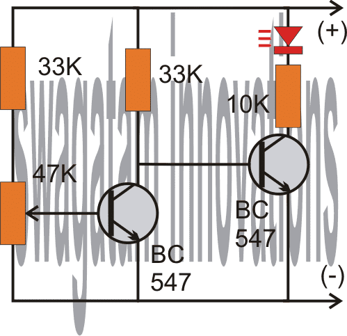
As shown in the following circuit diagram, the two transistors are configured as voltage sensor and inverter.
The first transistor on the left senses the threshold voltage level as per the setting of the 47K preset. As long as this transistor conducts, the second transistor on the right is held switched OFF, which also keeps the LED switched OFF.
As soon as the battery voltage falls below the set threshold level, the left transistor is no longer able to conduct.
This situation instantly switches ON the right hand side transistor, enabling the LED to illuminate.
The LED switches ON and provides the required indications of a low battery warning.
Circuit Diagram
Video Demonstration:
The above circuit was successfully built and installed by Mr. Allan in his paranormal depletion detector unit. The following video presents the implementation results:
Upgrading the above Transistorized Low Battery circuit into a Low Battery Cut-off Circuit
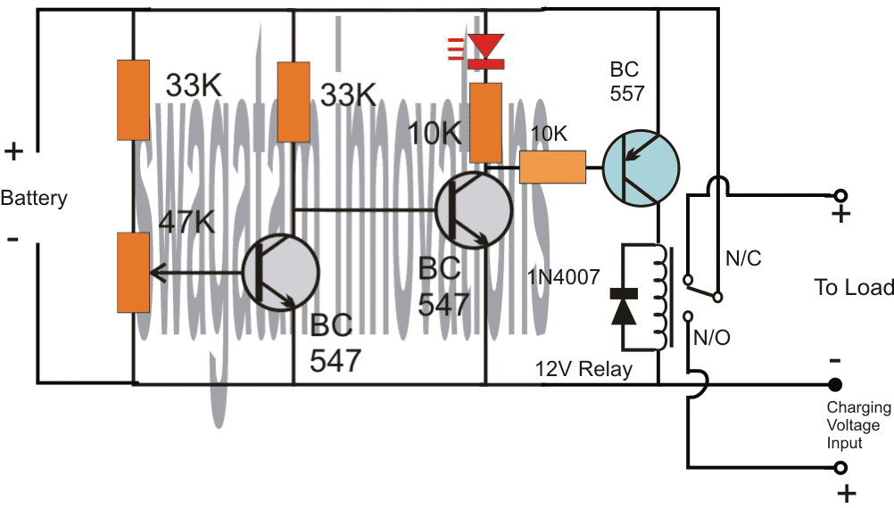
Referring to the above diagram, the low battery indicator is formed by the two NPN transistors, while the additional BC557 and the relay are used for cutting OFF the battery from the load when it reaches the lower threshold, in this state the relay connects the battery to the available charging input.
However when the battery is in its normal state the relay connects the battery with the load and allows the load to operate through battery power.
Adding Hysteresis
One drawback of the above design could be the chattering of the relay at the threshold voltage levels, due to the battery voltage dropping immediately during the relay changeover process.
This can be prevented by adding a 100uF at the base of the middle BC547.
However, this still wouldn't stop the relay from constantly switching ON/OFF at the low battery changeover threshold.
In order to rectify this, a hysteresis effect will need to be introduced which can be accomplished through a feedback resistor between the collector of the BC557 and the middle BC547 transistor.
The modified design for implementing the above condition can be seen in the following diagram:
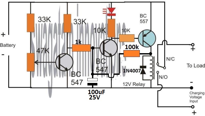
The two resistors, one at the base of BC547 and the other at the collector of BC557 decide the other threshold of the relay changeover, meaning the full charge cut off threshold of the battery.
Here, the values are arbitrarily selected, for accurate results these values will need to be optimized with some trial and error.
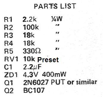
Low Battery Indicator using a PUT
This low battery indicator circuit is used with a programmable unijunction transistor (PUT), since the threshold characteristics of the UJT could be effectively defined, and can be designed to flash a connected LED indicator.
The PUT (Q1) is configured like a relaxation oscillator circuit.
As the supply voltage which is being monitored (Vmon) starts dropping, the gate voltage of the PUT (Vg) also begins dropping, while its anode voltage (Va) basically stays constant.
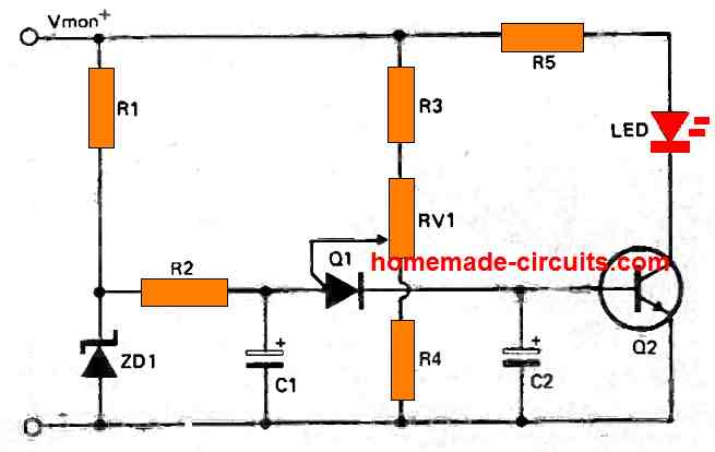
The PUT begins oscillating only as soon as the gate voltage drops below Va by 0.6 volts. As Vmon comes down further, Vg also drops accordingly and this situation triggers ON the PUT.
Therefore, the period of the cycle becomes lesser and this causes an increase in the frequency of flashing indicating that the battery has become too low and needs to be changed.
Parts List
Car Low Battery Monitor Circuit using a Single BJT
Here's a straightforward car battery monitor that eliminates the need for constant meter watching.
When your battery terminal voltage reaches a reasonable level, such as 12.5 volts as measured by a digital multimeter (DMM) or a reliable meter, you can adjust resistor R1 until the LED illuminates.
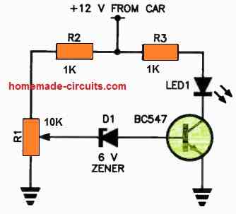
If the battery voltage drops below this threshold, the zener diode will switch to a non-conductive state, cutting off the base current to the transistor.
As a result, there will be no collector current, causing the LED to turn off.
If you don't notice the small indicator light shining on your dashboard, it could indicate a low battery condition!
It's advisable to use a green LED for better visibility. For R1, it's recommended to use a 10-turn trimpot for precise adjustments.


Questions & Answers
Can you give me the circuit to indicate the 6v voltage drop of the 8.4v source?
You can use the first circuit from the above article.
Feed 6V as the supply DC, and tweak the preset so that the LED just lights up at this supply voltage.
For the low battery indicator (2 transistor type), would I need different components for a 24V battery setup? Also: Could I substitute a lamp holder with a #387 lamp (28V, 1.12W, 0.04A) for the LED without trouble, or would changes be needed?
You can use the same circuit without any changes for a 24V supply, but for a #387 lamp you will have to replace the right hand side BC547 with a 2N2222 transistor. The LED + 10k resistor can then be removed and replaced with the lamp.
I suppose I could use a 50k trimmer for the variable resistor instead of 47k?
Sure, you can use it…
I want to latch the other circuit when the battery voltage is low but I need a positive voltage for that can I change right side transistor connecting it’s collector to positive supply so that I can get positive from emmeter will it work
Which other circuit are you referring to?
Hello again and thanks another reply. Now I understand. I didn’t realize that the potentiometer it’s self functions as a voltage divider. My only experience with them before now was when wiring my guitars and I always thought of them as them as purely resistive components. Anyways, appreciate the responsiveness
No problem! I am glad I could help. All the best to you.
Thanks again for the reply. I understand the concept of the circuit, just not how with the given values it would work. If the 33k and 47k potentiometer/resistor serve as a voltage divider, then wouldn’t the voltage have to drop to around 1.5 volts before the first transistor would stop conducting?
The potentiometer can be used to adjust the cut off threshold to any desired value with respect to the battery voltage. So if you want the left BC547 to cut off at 11 V, you can adjust the potentiometer accordingly, similarly you can do the same for any other battrety voltage such as 10 V, 10.5 V or 9V etc. The potentiometer gives you the full freedom to adjust the cut threshold to any desired values, as required.
Hello, not understanding the circuit function of the first 3 diagrams. Wouldn’t more voltage drop across the 33-k resistor biasing the led transistor since there’s the additional 48 k at the base of the first? Also why is there any arrow pointing outward from the base of the first transistor being an npn? Thanks
Hello, the 47K resistors is a potentiometer, or it can be a preset, or a trimpot. The arrow indicates the wiper arm of the potentiometer which is connected with the base of the transistor.
Thank you for the response. I’m still not understanding how the first transistor stops conducting at the threshold voltage with it being above 0.7 volts or how the other transistor doesn’t conduct first being that there’s less resistance to its base? I’m new to electronics so I’m probably missing something obvious here.
Let’s assume the 47K trimpot is adjusted such that the base voltage of the left BC547 drops below 0.7 V when the battery voltage drops below 11 V. This means, as long as the battery voltage is above 11 V, the left BC547 remains switched ON, which causes the base voltage of the right side BC547 to be grounded. Due to this the right side BC547 remains turned OFF, and the LED also remains shut off.
Now, in a situation when the battery voltage drops below 11 V, the base voltage of the left BC547 also correspondingly drops below 0.7 V, which causes it to shut off. When this happens, the right side BC547 base starts getting the biasing voltage through its 33 K resistor and it switches ON. This also allows the LED to switch ON and indicate the low battery condition.
Nice, but a bit dated.
PMIC supervisor IC chips have long since advanced the art of low voltage detection. The operating currents are in the 10uA to 1uA (micro) range. The pin counts are down to 3 pins. Hysteresis is built in. Price is under 50 seconds for singles and dirt cheap for larger quantities.
Hello sir, please I need your urgent help with this; Is there a way you could modify your above circuit further to include another stage of switching so as to sound a buzzer alarm at 11 volts (for a case of 12v power supply) to warn of low battery before switching of the relay at about 10.5v. I have really tried this with a trial and error method several times, wasting a lot of transistors in the process. Please sir, I would be glad you illustrate with with a diagram. Thanks in anticipation.
Hello Chinomso, there’s no question of wasting transistors in the above circuits, because the transistors are safe and can never burn.
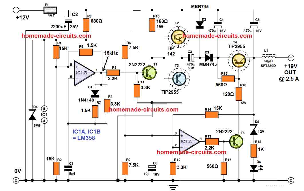
If you want a sharp response then instead of transistors you can use an opamp based design, as shown below:
This had been designed for SG3525 inverter, therefore ignore the pin#10 indication.
Also you can remove the 4k7 and 1k from the output of the opamp and connect the buzzer directly from battery positive to pin#6 of the op amp.
You can remove the hysteresis network which uses 1N4148 diode and series 1K.
You can make another similar circuit for activating a relay through a driver transistor. If you are using a transistor with the op amp then the 4k7 and 1k at the output should be included in the circuit, and the transistor base connected to the 4k7 / 1K junction.
Hello sir, can LM393 opamp be used in the two stage mode, such that : the pin 1 of the ic, for instance, controls the relay, while the pin 7 controls the buzzer for low battery warning?. If it can, please i would be very happy if you could provide me with good diagram to that design. I would love to use 741 opamp as you adviced, but considering space, power consumption and circuit ambiguity, I would want it on a single source. Thanks
Hello Chinomso, the IC 741 can be used with a single power supply, the -battery indicates the 0V or the ground of the Dc supply.
You can try the following configurations using the LM393 IC:
Thanks alot sir, I’ll try this
You are welcome Chinomso, there’s a small mistake in the diagram, the feedback diode 1N4148 must be connected to pun#3 of the opamp and its polarity must be reversed.
Thank you so much for the circuit, I really appreciate. However sir, i chose the transistor based because I really want to save as much power as I could. Hence, the circuitry should be such that it would be required to have a two stage switching, such that a set of transistors in TTL mode switches the buzzer on at 11 volts, then as the battery voltage reduces further to 10.5 volts, another set of transistor switches off the relay. I need this in my inverter circuit and would so much appreciate it I could get this from you. Thanks alot
Hello Chinomso, transistor circuit will not be able to provide precise cut offs, sometimes it may be at 10.5V and sometimes 10V or sometimes 10.8V
I really would be completely blind to these things If not for your help. I really appreciate you sir
I am glad to help Chinomso!
Can BC337 be used instead of BC547 in first circuit?
Yes, can be used.
Hi sir
Can this be optimized for 24 v system
Hi Gogulanath, you can use the same circuit without any customization for 24V also….for the relay circuit, you may have to replace the 12V relay with a 24V relay.
Thanks for this site and for posting this circuit. I have been getting back into electronics with my kids after many years off and your site is great for that purpose. I have a couple of questions about the first circuit (the one that only lights the LED).
1. In the 12.5V +/- 1V range using a 10k LED for the load this circuit will power the LED with 1.2mA. What LED works at 1.2mA? I usually see current ranges in the 20-30mA. I think I need to lower both the LED driving transistors base and collectors resistors substantially. According to LTSpice 10k and 390 are working values for those two resistors.
2. How stable do you think the triggering threshold be over time? Let’s say that it triggers at 12.5V at room temp using a BC547B (which may or may not have higher gain than BC547). How likely is it to trigger at the same over a long period of time and a range of different temperatures?
Thanks
Thank you for asking this question:
1) I normally use 10K for my red LEDs since they look too bright for any other lower resistor values. The resistor values can be tweaked, there are no criticality regarding the values of the resistors, because ultimately it’s the preset adjustment that decides the detection thresholds.
2) The transistors will start giving wrong results after around 37 or 40 degrees Celsius, under this the results can be expected to be fairly consistent. The preset quality will also affect the results over a long period of time, since the preset contacts may get dirty and loose or might deviate from the initial adjustment.
Thanks a lot sir, This circuit is very helpful to me and it is easy to understand ????
You are welcome Yogesh, I appreciate your kind feedback!
Hello
I have a battery holder that doesnt have a battery low indicator but I have access to the board.
This solution is exactly what I am looking for. Can you help not an EE
What help do you need?
As you know, I don’t know much but it looks like it might be easier to keep with your initial design for low battery but have it wired to an additional green LED that is manufactured to blink or flash. I think they make them like that. Am I right to stick with your old way and have the additional blinking green LED?
No Problem Dane!
I forgot to mention I will be using a 9 volt battery
I found a guy who is trying to design a PCB for me. I am very excited and will keep you posted.
Thank you so much for your help. I was wondering if you could help me again.
I am wondering if there is a way to adapt and change your low battery circuit to do what I need.
I have a switch that operates from 1 volt to 24 volts. It has 3 connectors. One is a Common. The other is a Normally Open connector that goes to my Green LED when the switch is on. It has a Normally Closed connector that goes to my Red LED when the switch is off. I would like to avoid adding another LED for the low battery indicator (was going to use a yellow led). Instead, is there a way to make my Green LED blink on and off when the battery gets low? Using only 2 LED’s would really help. Thank you again for your input.
That great news! However, getting the LED to flash can make the design a bit complex. You can try the last circuit explained in the following article, hope this might help you accomplish your requirement:
https://www.homemade-circuits.com/flashing-led-battery-status-indicator/
I will look into finding a company that can do that here. Thank you again!
Sure, I hope you find an appropriate source soon.
Great! Thanks for the clarification. I will start with the 2K2 and see if it’s bright enough. I have a hand drawn diagram of what I am trying to accomplish but it is terrible and I am too embarrassed to post it publicly. I think I am going to need someone to draw it out for me so that maybe I can have a small PCB made. Any ideas on who might be good to help with that?
Thanks again!
Thanks very much, I understand your problem, however I do not have anybody who can design PCBs correctly, since it is a specialized job and must be done in accordance with the standard PCB designing rules. I guess Only a PCB manufacturer will be able to draw it correctly.
Hi again!
Could you please clarify the circuitry of your low battery warning design?
The photo you sent me shows a 1k resistor (bottom right) but the diagram shows a 2k2 resistor.
Which one should I use?
Hi, It can be any value between 680 ohms ohms and probably 10 k for supplies between 9V and 15 V, so you can use any resistor between this range although the light will decrease as the value is increased.
Will do!