In this article I have explained a simple battery health checker circuit which uses ordinary components for enabling the user to get an instant reading of the battery efficiency or regarding its effective discharge rate. The idea was requested by Mr. Shrishail.
Circuit Objectives and Requirements
- Nowadays i confirm the battery depicted below.
- First the battery under evaluation recharge fully with normal charger, which goes through its specific time to charge completely.
- After that I hook up certain load that is able to discharge the battery upto reasonable limit. as just stated it consume its specific time to discharge entirely.
- Subsequently I assess the time utilized by each of the above measures
- Using this method is extremely time intensive & tier-some.
- For this reason I require the circuit as above noted battery checker
The Design
In one of the previous posts I have explained regarding the significance of internal resistance of battery and realized how this parameter affects the efficiency of a battery in terms of its charging rate, and discharging rate.
The internal resistance of a battery ultimately decides how much current the battery may be allowed to accumulate, retain efficiently and discharge at the same efficient rate to the load.
Higher internal resistance would make the battery lower with its efficiency and vice versa.
Therefore the health of a battery can be evaluated by correctly and quickly judging the average internal resistance of the battery, but since this method may not be easy to detect using ordinary methods, an alternative way of determining the health of a battery is to capture the instantaneous amount of current it's able to retain, and deliver through a quick discharging method.
This procedure is devised by me, although I am not sure whether or not this would be helpful enough in determining or checking the health of a battery quickly.
Circuit Diagram
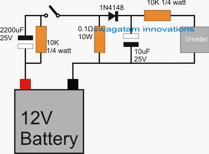
The diagram shows the proposed battery health checker circuit using very ordinary components and the set up hopefully can be used for determining the battery's overall condition by pressing ON the switch.
First the battery is charged to an optimal extent, this procedure cannot be avoided because unless the battery is properly charged the level of current it has retained cannot determined.
Hence after the battery is optimally charged using any ordinary high current battery charger, the above shown circuit set up can be attached with the battery for getting a rough idea regarding its AH efficiency specs.
How the Circuit Functions
The circuit is supposed to function in the following manner:
As soon as the indicated switch is pressed, the battery is subjected to an instantaneous short circuit condition via the 2200uF capacitor and the 0.1 ohm resistor.
This action forces the battery to throw its stored maximum current across the 0.1 ohm resistor, which in turn develops a equivalent amount of voltage across the 0.1 ohm resistor.
This equivalent amount of voltage which is supposed to be the direct measure of the battery's AH efficiency level gets stored in the 10uF/25v capacitor and can be measured or read over any suitable digital voltmeter across the selected range.
By performing a few repeated tests through the above method, and by assessing the corresponding voltage levels across the 10uF capacitor, an overall health of the connected battery can be estimated and checked.
The values of the 0.1 ohm resistor may vary according to the AH of the battery, and must be selected appropriately such that a measurable reading is achieved over the selected range of the V meter.


Questions & Answers
WHAT COMPONENT SHOULD I USE FOR A 36V TO 750 AH BATTERY
The capacitors must be rated at 60V or higher, rest all can be as is…
though it’s a diesel generator but its still fully operating using battery power.thanks for your quick response
OK, you can try a relay with a 40 amp contact
Thanks sir.Pls,if I want a 24v 400arms battery to N/C or N/O to contact on a relay so that a generator will start through that battery.What’s going should be the relay rating.thanks.
Hi Nsonic, is the generator supposed to only start with the battery or fully operate using battery power?, in other words is the generator a diesel powered or battery powered system??
Hi Mr swagatam,when I put the multimeter,what is going to display as no if the battery is healthy or not. (2)What’s another method of testing an healthy battery.
Hi Nsonic, it will display some value which can be compared with the value of a good battery. The good battery value can be saved as the benchmark level, and the doubtful battery values can be compared with this good battery reading for the estimation
hi, your circuit is great, can this battery health checker be measure 100ah?
Hi Edmund, if the metal resistance is within the range and capacble of generating the required potential drop then it can eb used.
the short circuit will probably last only for some milliseconds, so a 10 watt resistor will not heat up or get burnt, even with repeated tests, in my opinion.
Hi, sir i have 2nd question. Can resistor 0.1ohm 10watts can be replaced with a metal rod? Just like in battery tester use by battery dealer. Cold cranking tester. Wherein for several testing the inside metal rod becomming to hot turning red hot. Specially if you test several battery. I think 10watt resistor will broke for heat. Thanks.
Hi, yes it can be used for any battery with any rating
Hi Swagatam.
Would I need to change anything to use on 6 volt batteries?
Regards,
Conrad
Hi Conrad, No change would be required for a 6V battery, the same set up can be tried for it also.
Thank u Very Much for this very simple, low cost & basic circuit. And , last but not least, for ur kind attention to my small problem.
It's my pleasure Shrishail!